Dragon (DML) 1/72 Ar 234B-2
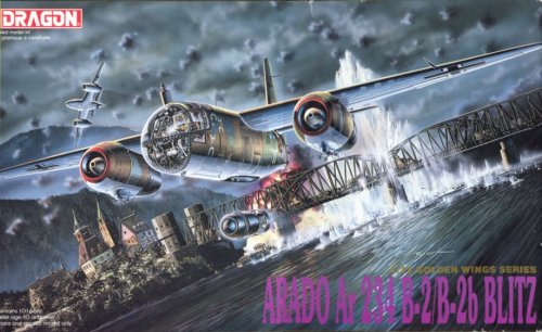
| Now and then I get the irresistible urge to buy a new model that I can build straight out of the box. Almost always these plans fail miserably, because I get too interested in the subject, or the model has faults that I cannot ignore. Here is one of these projects, and so far, things are going pretty much according to plan (amazingly). Maybe it helps that I have close to no references on the subject. But I really like the concept, a fairly small single-seat jet bomber. And it being a contemporary to the Me 163B (see my Komet web site) probably helps too.
|
The model
I researched the Dragon model a little before I bought one at an IPMS meeting. Generally, the reports were very favourable. However, knowing Dragon aircraft models, I also expected fit problems, unnecessary part breakdowns, a slightly pebbly surface, and useless photo-etch (as in: plastic parts would have been better). Most of this turned out to be not applicable for the Arado, it's a very decent kit. It looked very pretty on the sprues, and very small! The building process revealed some problems, that are discussed in detail in the build report.
On the positive side:
the model portrays the Arado 234B accurately as far as I can tell, both in shape and size (see measurements below), a very important plus
the panel lines are just of the right width and depth for me, another very important plus
the cockpit is nicely detailed
I did not find any major problems, only small ones
On the negative side:
the cockpit glazing consist of no less than four parts. The two main parts differed in width in my kit
the cockpit glazing fits badly on the fuselage, but it can be solved
the lower wing inserts fits very loosely in the upper wings, I had to use plastic card filler plates
wing fit on the fuselage is very vague, I had to pack the tabs to create a solid fit, plus a simple jig to get it right
the chord and span of the flap segments is too small (see build report)
the transparent insert in the rear fuselage requires extra attention
the bomb recess under the fuselage is represented in an unrealistic way
the engine inlet ducts are about half the real length, but it's not very visible.
the decals are not very good
Since the kit contains both camera equipment and a bomb, you can build either an Ar 234B-1 recce version or an Ar 234B-2 bomber version. According to period Arado/Luftwaffe drawings, the B-1 was supposed to be fitted with two rearward-firing MG 151 in a semi-flush belly gun pack, but this is not included.
I measured eleven dimensions of the model. Differences with the published Arado data (see drawing below) are minimal, so I'll give the kit an OK on this aspect.
|
| Arado data
| Dragon model
| Comments
|
|
| mm (1/1)
| mm (1/72)
| mm
| diff.
|
|
| Fuselage length
| 12640
| 175.6
| 174.5
| -0.6%
|
|
| Fuselage width
| 1400 ?
| 19.4
| 19.7
| +1.3%
| real dimension difficult to read
|
| Wing span
| 14410
| 200.1
| 199.0
| -0.6%
|
|
| Wing root chord
| 2550
| 35.4
| 34.5
| -2.6%
| kit dimension not measured on centerline
|
| Wing tip chord
| 830 or 850 ?
| 11.5 / 11.8
| 11.5
|
| real dimension difficult to read
|
| Horizontal tail span
| 5000
| 69.4
| 69.8
| +0.5%
|
|
| Horizontal tail root chord
| 1150
| 16.0
| 16.2
| +1.4%
|
|
| Main landing gear track
| 2050
| 28.5
|
|
|
|
| Main landing gear tire diameter
| 935
| 13.0
| 12.9
| -0.8%
|
|
| Main landing gear tire width
| 345
| 4.8
| 4.8
| 0
|
|
| Nose landing gear tire diameter
| 630
| 8.8
| 8.7
| -1.1%
|
|
| Nose landing gear tire width
| 220
| 3.1
| 2.9
| -5.1%
|
|
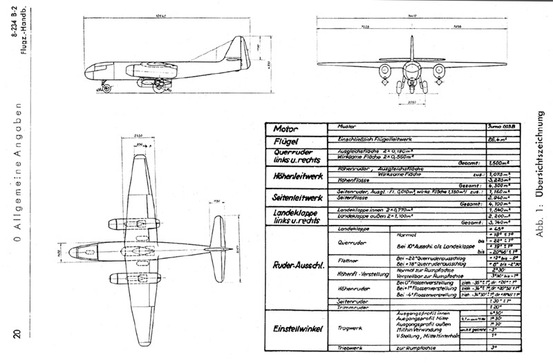
Later I found a review of the Kagero / Casemate 'Arado Ar234 B-2, B-2/N, C-3' (Top Drawings 105) book, and I noted that the fuselage cross section was different from that of the model. The model is basically a square or rectangle with rounded corners, the drawing shows slanted sides. I do not know which is correct.
Three-quarters down the project, I found the drawing that must have been the source for the Dragon model. AeroModeller magazine, March 1972 issue (PDF download at RC Bookcase), contained a six-page article with very nice drawings by Barrie Hygate (who wrote 'British Experimental Jet Aircraft' in 1990). Almost every drawing item checked perfectly with the model, down to the smallest detail. Take the row of hatches beneath the wing's leading edge as an example. The drawing is also the source of the flap segments that are too small.
'Aero Detail 16 - Arada 234 Blitz' from 1996 also contains drawings, but since this book was published years after the model was issued, it cannot have been the information source. The Ar 234B drawings look a lot like those from AeroModeller. The only difference I spotted so far is the periscope in the front view drawing.
Model variants
Here's a listing of all original issues of the Dragon Arado 234. The B-model from 1992 (5003) is the rarest of the lot on the second-hand market, I usually see the C-models offered.
5003: Ar 234B-2 two-engine bomber, with one 1000 kg Herman bomb, two drop tanks, two Walter RATO pods
5004: Ar 234C-3/4 four-engine bomber, with three 500 kg bombs, one BT400 torpedo bomb and two drop tanks
5011: Ar 234C-3 four-engine V1 launcher, with three bombs, two drop tanks, one BT400 and V1 with launch trapeze
5012: Ar 234B-2N two-engine night fighter, with two drop tanks, twin gun underbelly pack and Walter RATO pods
5026: Ar 234P four-engine radar fighter, with two drop tanks, one BT400 and a semi-recessed underbelly gunpack
9005: Ar 234C four-engine, with Arado E.381 Julia parasite fighter, three bombs, one BT400 torpedo bomb and two drop tanks
The Arado 234B was reissued in 2019 by Platz, with four decal options, catalog number AE-14; see Hobby Search site. In 2021, Polish brand 'Hobby 2000' also reissued the model, in two boxes. 72039 is titled 'Arado Ar 234B-2 First Jets', 72040 is titled 'Arado Ar 234B-2 End of War'. Each box contains two decal options, photo etch and masks.
Accessories
Around 2005, there were only a few accessories on the market for this model. I noted an Airwaves photo-etch set (2078), an Eduard photo-etch set (72-182), a resin Junkers Jumo 004 from Engine & Things (72-129), and lastly a 'flattened & bulged' wheel set by True Details (72042). I decided against buying any of these, considering the straight out of the box character of this project.
One aftermarket part that sounds intriguing is a replacement vacform canopy. Falcon Clear-Vax canopy set 29 contains one for the Arado Ar 234B, and is listed as made for the Dragon kit (see instruction sheet).
Construction
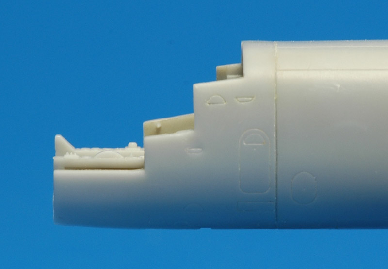
| Construction started with an annoying break in the front fuselage. It's probably required for commonality with the Ar 234C model. I glued the parts together very carefully, doing my utmost best to avoid a step. The edges of the parts were quite rounded, and a very deep 'panel line' remained after the operation. It fell very out of tune with the rest of the panel lines. Therefore, I filled it completely with CA glue, and scribed a new panel line. Since the CA is transparent, the result is difficult to judge, and a coat of paint is needed to see the quality.
| 
|
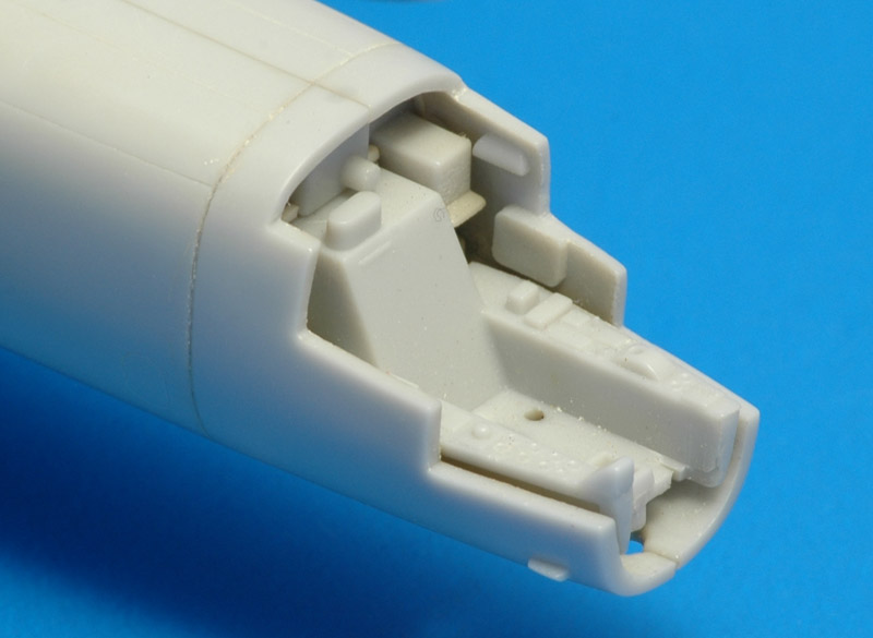
| For the cockpit, I decided to deviate from Dragon's construction sequence. It seemed better to fit the cockpit tub after assembly of the fuselage halves: it would allow progress with the overall assembly while I could work on cockpit detailing. I had to check whether the tub could be inserted with the rear cockpit bulkhead in place. This turned out to be possible, and therefore I glued the bulkhead in place. It had quite a gap all around, and I hid this by gluing a piece of plastic strip around the joint. In the photo the tub is fitted to the fuselage. The detailing of the tub is nice, and I will not replace it with photo-etch details.
|
The fit of the canopy on the fuselage is pretty bad: it seems the clear parts are smaller than the fuselage, and the rear part of the canopy sits too high. Since the clear parts cannot be modified, the fuselage has to give way.
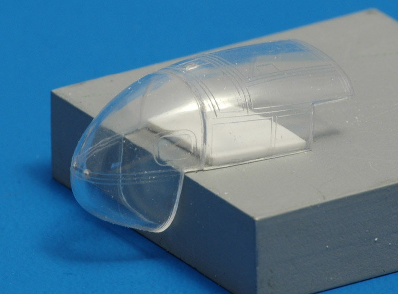
To check the fit, you first must assemble the two main parts of the canopy. More problems: the front part is wider than the rear part. The only solution I saw was a risky one. I glued a piece of 1mm plastic card on a metal block. I cut the card to a width that was slightly larger than the internal dimensions of the rear canopy part. I then spread the clear part slightly and pushed it over the card. It now had the same width as the front part, and I used CA glue to bond them together. I risked CA fogging, but by using only small amounts, this did not happen fortunately.
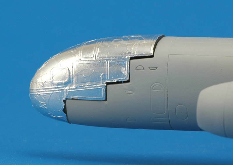
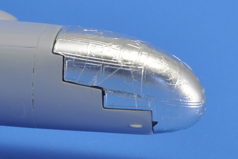
I now had the basic canopy to check for fit on the fuselage. Because of their clarity, it is difficult to judge how well the clear parts fitted on the fuselage. I covered them with Cheap Chocolate Foil to make things easier. Lots of fuselage sanding later, the fit was acceptable.
| 
|
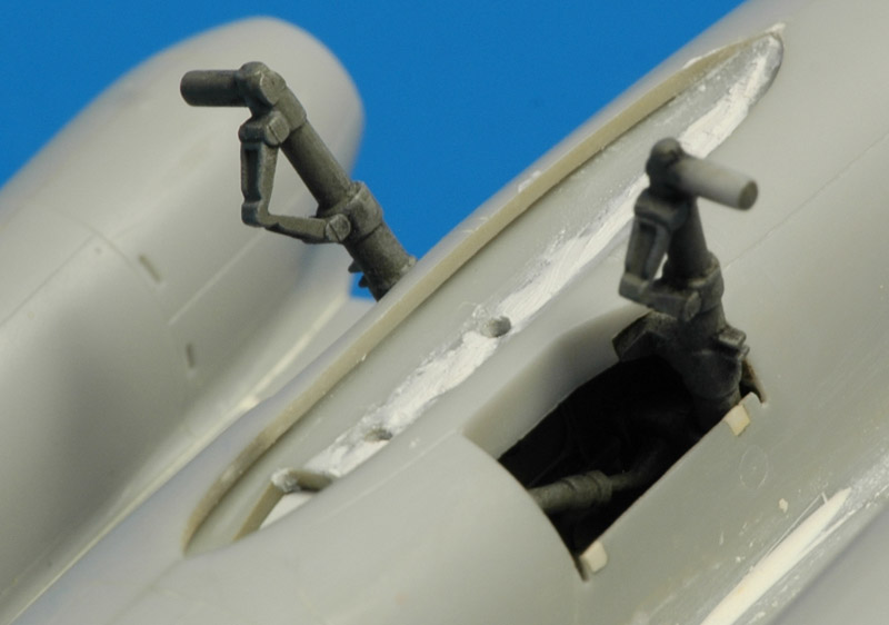
| Another item to deal with, before the fuselage could be closed, was the main landing gear. First, I filled the oversized cut-outs for the door hinges. Later I sawed new ones at the outboard edges of the wheel bay. Then I mounted the main landing gear legs on their bases. This seemed like a very fragile joint, so I reinforced it with pieces of plastic. These reinforcements, deep inside the wheel bay, aren't visible from the outside.
Another problem with the fragile mounting of the main landing gear legs is that they also allow one to install the legs at a wrong angle, making the wheels toe in or out. That happened to one leg. I will have to fiddle with the wheel a bit to solve that. I painted the legs and wheel bays with a RLM02 look-alike color. I still have to paint the oleo part of each leg. The oleo length suggests an aircraft that sits way too high, but as far as I can see now, that's not the case.
Dragon modeled the recess for the centerline bomb rather strangely, as you can see here. Five photos down you can see how I modified it.
|
Over to the wings and engines. The wings couldn't be assembled straight from the box. All along the flap's leading edge, the lower half of the wing didn't make contact with the upper half, it floated free so to speak. I had to pack the upper half with strips of card, and then I could glue the halves together.
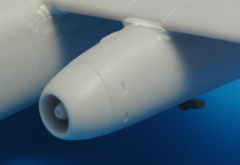
Next were the engine nacelles. The front part (that included the compressor face) didn't fit too well, but some sanding solved that. The glue line had to be scribed to make it a neat panel line again. By the way, one of the starter motor 'bullets' inside the intake has a pretty bad lean to one side, but there is almost nothing that can be done about it, except drilling it out and replacing it.
In side view, the nacelles have a nose-up attitude, that compares well with photos.
Much later I read a build report on the Fly Ar234 by Steve Gallacci on LSP, and among others the builder lengthened the inlet ducts to a scale ~875 mm, translating to 12.3 mm in 1/72. The model has the half of that, but it's too late to change that now.
| 
|
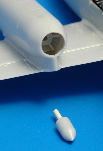
| To make painting of the turbine end of the engine possible, I cut off the 'onion' before I assembled the nacelle. A piece of rod and a hole in the turbine face (inside) allows assembly afterwards. Later I filled the cavity inside the exhaust's top side with Milliput.
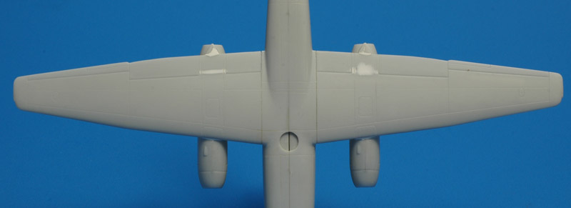
The photo shows another small problem, that is easily solved. As you can see, the flap seems to continue over the nacelle. The flap panel line has to be filled about 1 millimeter on either side. Strangely there are raised panel lines on the flap that need rescribing. Lastly, I used Milliput to fill all the gaps along the leading edges of the flaps and ailerons on the lower side. The fit of the wing's lower sides against the fuselage was pretty bad, and as you can see I used a lot of Milliput there. All in all, the wings required quite a bit of work.
Knowing the error in the inlet duct length, I wonder now whether the turbine is (way?) too far aft..
|
The flaps are moulded with the upper wing surface, which makes for a nice, sharp trailing edge. But the large plastic volume of the flaps also means mould shrinkage problems. Just behind the flap hinge line, a shrink area has formed on the upper wing surface. It is most notable in the nacelle area. I used CA and Milliput to fill these spots. Later, using a strong point light, I noted similar shrink areas on the lower side of the four flaps.
The fit of the wings to the fuselage is very loose, they can flap about 20 degrees! I glued several pieces of thin plastic card on the mounting tabs, and this took out most of the play. I read that the 234 had zero degrees dihedral. I calculated that, due to the taper, the upper surface of the wing tip should be 1.5 mm below the upper surface of the wing's center section. I built a simple jig from a square wooden stick, with 1.5 mm thick card at the appropriate places, and glued the wings to the fuselage. The fairly rough joint was then filled with more CA glue. I rescribed the center section according to a drawing in the Monogram Monarch #1 book. It appears that Dragon forgot the rear spar panel line, so I added that too.
This view also shows a planform problem: the trailing edge of the outboard flaps is curved, but should be straight. See also the photo above. I corrected that later. NOTE: maybe the outboard flaps had a curved trailing edge after all. I cannot find conclusive proof of either. The official Flugzeug-Handbuch 8-234B-2 shows straight trailing edges in figure 47. The Monogram Monarch's drawings shows straight edges. The Hasegawa 1/48 model has a curved edges, but the Fly Models 1/32 model has straight edges. Photos of the real thing would be the definitive proof though, not the model interpretations.
The build report on the Fly Ar234 by Steve Gallacci on LSP revealed another problem with the model: the chord and span of the flap segments are considerably too small. A photo in Aero Detail 16 shows this very clearly. But it's too late me for.
| 
|
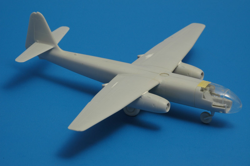
| The result so far, with some parts temporarily fitted. At this point of every straight-from-the-box build that I attempt, I start to regret the rather static pose of the aircraft, with all control surfaces undeflected.
Much later I read in 'Flugzeug-Handbuch 8-234B-2' (page 20 and 113) that dihedral was not zero but one degree. It's too late to change that now. The incidence angle is 4 1/2 degrees, and the kit is close to that figure. The nacelles are at 3 degrees 'incidence' to the fuselage (page 125). The wing twist is -3 degrees, and I don't see that in the model's wing.
|
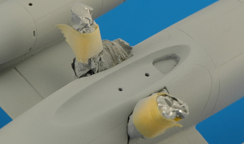
Here is the centerline bomb recess again. I applied Milliput all around the inside of the edge, and used a small steel ball to create a nice curvature from the edge to the centerline. This approximates the shape of the real thing a lot better. But note that I found only a single photo that area. I might improve it a bit more with a recessed rectangular area that housed the suspension lugs, in the area that now has the two holes.
Also, I applied a light grey enamel paint to find small build defects, and I found plenty that required attention.
| 
|
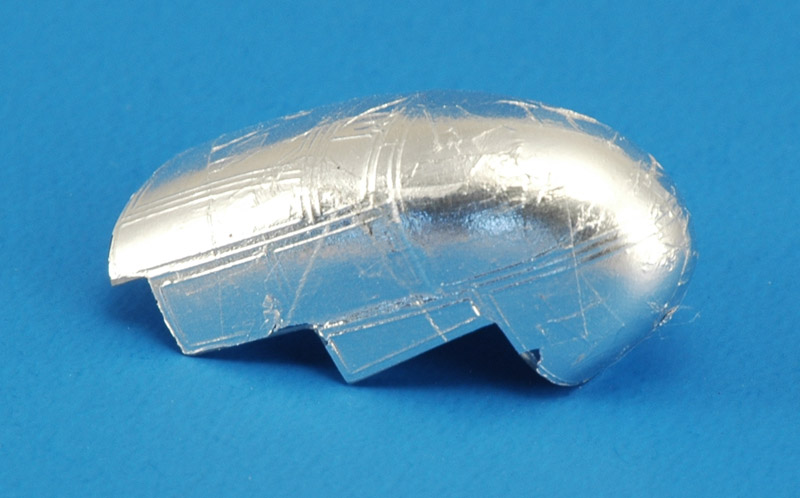
| Another job that I had postponed was added the two small windows next to the side consoles in the cockpit. A four-part canopy on a 1/72 scale model, who thinks it up? The main problem is that you cannot judge the relative position of clear parts well. To see what I was doing, I covered the whole canopy and the two windows with Cheap Chocolate Foil (CCF), and attached the windows with tiny drops of CA to prevent fogging. I had to repeat this process a couple of times before I thought it looked good enough. I then partially removed the CCF, to add more CA to strengthen the joint without the chance of CA being sucked under the CCF because of capillary action. By then my patience was thoroughly exhausted..
|
| Next, I test-fitted the now complete canopy on the front fuselage, only to find out that it would not fit properly. Several modifications of the fuselage side will be required. The fit problem was mostly solved by removing 0.5 mm from the fuselage below the side windows that I added in the above step. But now the front part of the canopy extends below the fuselage. I also noted the canopy did not want to sit straight on the fuselage, it would point slightly to the left. I solved that by scraping a bit of plastic off the vertical walls on the right side.
| 
|
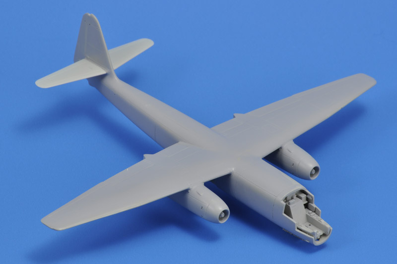
| A big step forward was converting the paint system from Humbrol enamel paint to MRP acrylic lacquer. I first sanded the roughness of Humbrol 127 (previously my standard base coat) with 800 grid paper and 1200 grid scotchbrite. Next was the first layer of MRP-38 light grey, that mostly filled the roughness of the Humbrol paint. Next the model was sanded with a combination of 3M 1000 scotchbrite and Micro Mesh 3200, to take off the last roughness. A second layer of MRP-38 (still to be applied) will finished the job.
A small note: I filled the the camera hatches on the top and bottom of the rear fuselage. I'm not 100% sure that these were deleted on the bomber (B-2) version though, but I thought it made sense.
|
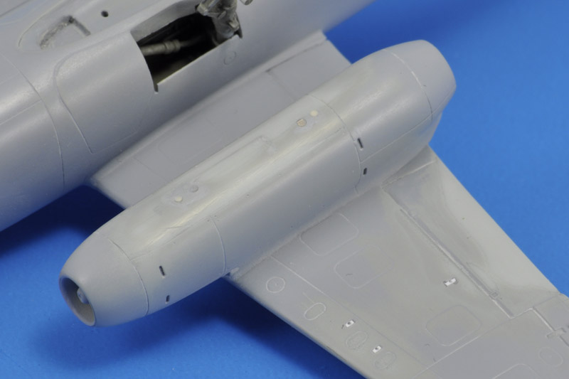
On the lower side I found some details that required decisions. What to do with the holes for the engine nacelle pylons, and the holes for the Walter rockets? I decided to fill the later, since I had no plans to add these RATO units. I inserted small pieces of plastic strip and used CA to fill the gaps around them, then drilled a shallow 0.5 mm hole in each filled slot.
Regarding the pylon mounting holes, I still didn't know what I want to do, and decided to play it safe and install small 1 mm magnets. The magnets will allow both options, pylons on and off. I installed the magnets 2 mm away from the kit pylon holes, so I would have more room in the pylons to install the counter-magnet.
| 
|
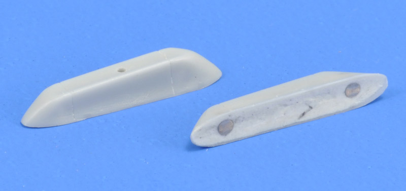
| The counter-magnets inside the pylons are 2x2 mm ones, that required some drilling of the pylon interiors. After mounting the magnets with CA glue, I filled the interior of the pylons with Apoxie. At that point I noted that the kit also contains another type of nacelle pylon (part 24), and I don't know which was used when. The alternative pylons are too small to install magnets, so I can forget about them. They are not shown in 'Flugzeug-Handbuch 8-234B-2'; it only shows the box-type pylons ('Traggerüst'). I still need to detail the pylons a bit with a few panel lines and some holes.
|
I modified 5 of the 12 contact areas between the canopy and fuselage until it the canopy sat flush. To my surprise the canopy had not been lowered to such a degree that a step at the lower front occurred.
The photo also shows the 'crunchy' panel line at the fuselage-nose connection. Oh, how I dislike glue joints that do double duty as panel lines. If I was smart I would engrave a new one, 1 mm back or forward. But fortunately I found a new way to improve them. Instead of painting them over with enamel, and then sanding away the excess, I discovered that smearing the paint into the panel line with your finger works way better. It improved the crunchy panel line dramatically in one go.
| 
|
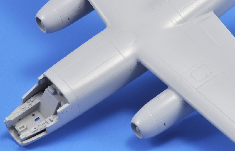
| Here's the result of switching paint systems, from Humbrol to MRP. The first coat of MRP mostly filled the roughness, followed by some sanding with a 1000 grit sanding sponge, followed by a second coat of MRP. This is the paint quality I've always looked for. And the crunchy panel line has improved a lot after the Humbrol paint smear.
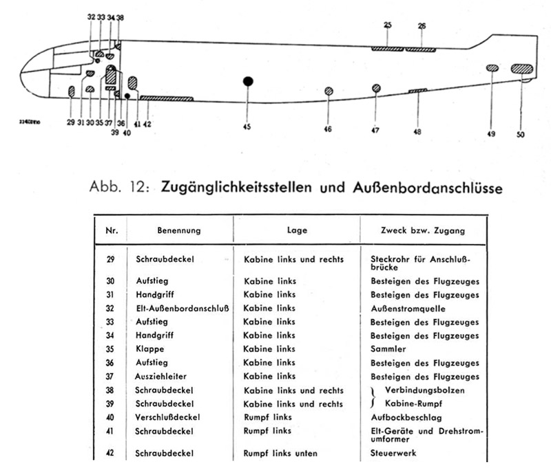
The circular insert on the fuselage-wing transition (part B22) has a mounting base for a direction finding antenna. But on V10/PH+SR it was still mounted on the rear fuselage, therefore I made the hatch smooth. But possibly the hatch wasn't there at all, I don't see it listed in figure 12 of the Flugzeug-Handbuch 8-234B-2. However it is shown in figure 79 as 'Peilrahmen' which translates as 'direction finding antenna'. I decided to leave the hatch as it was.
The model has another mounting base for a direction finding antenna on the fuselage near the fin's leading edge. Unfortunately I removed that as per instructions.
|
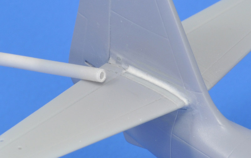
| The last major parts that required work were the horizontal tails. To cover the glue joint I made a nice rounded fairing, using Apoxie and a piece of 2 mm tubing to create a continuous radius along the length. After painting I will know whether more work is required.
| 
|
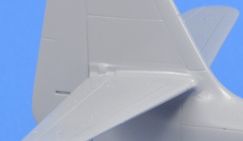
| Here's the result after painting. It looks very natural to me eye, and I'm happy with the result.
Later I found out that the horizontal tail had a variable incidence, rotating around the front spar probably. Therefore it probably had scuff plates at the root, and I'll need to scribe a line.
|
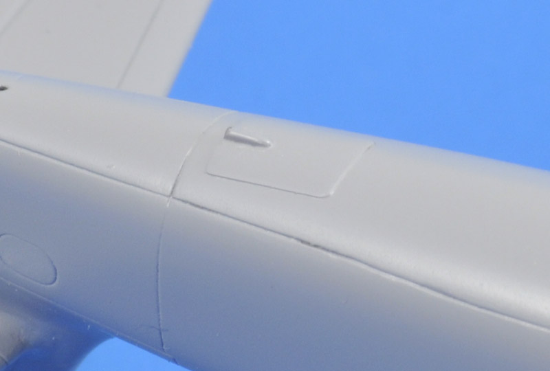
| On the rear fuselage bottom, the shallow panel lines of the parachute hatch had largely disappeared. I tried rescribing the hatch with a photo-etched template, but it became a mess. I then found a photo of the real hatch, that looked like it wasn't mounted flush, and I decided to copy that. I used a piece of 0.2 mm plastic card and added a tiny fairing for the lead cable.
| 
|
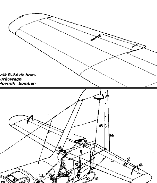
| I enjoyed seeing the Arado Ar234 - Dragon 1/72 by Giampiero Piva on BritModeller. He mentions that "the trim actuators (2 above and 2 below) and the aileron actuators (2 above) must be added to the wings". I found the actuators on the top side in a cutaway drawing, and a photo showed that there was a trim actuator on the lower side too.
The above raises the question whether there were actuators on the tail planes and their trim surfaces. The cutaway drawing does not show them. However, further research showed that the drawing was wrong in showing elevator trim surfaces, the real thing did not have them. All-aero reports: "The cantilever tailplane was an all-metal stressed-skin structure, pivoted on self-aligning bearings at the leading edge. Incidence of the entire surface could be varied by a screwjack controlled by a lever in the cockpit. The narrow-chord metal elevators had no trim tabs". And the model has a rudder trim tab actuator on the left side. Therefore the tail does not need additional details.
|
To be continued
Colors
I will paint my Arado in RLM 70, 71 and 65. The latest references are very clear about the use of these early war colors on the late war Ar 234B, which makes sense since they were prescribed for bombers and destroyers during the whole war. Still, most modelers insist on using late war fighter colors RLM 81, 82 and 76 on their Ar 234B models. I get the impression that they want their model in late-war colors, ignoring evidence to the contrary. Or they follow the horrible NASM over-restoration paint scheme. There, I said it: NASM, over-restoration and horrible in one sentence! For masking the camouflage, I might try LF Models mask M7226.
In the YouTube video linked below under 'References', the exhaust color is notable, very light. On V9 / PH+SQ only the 'onion' is light, on V10 / PH+SR the whole exhaust is light-colored.
Markings
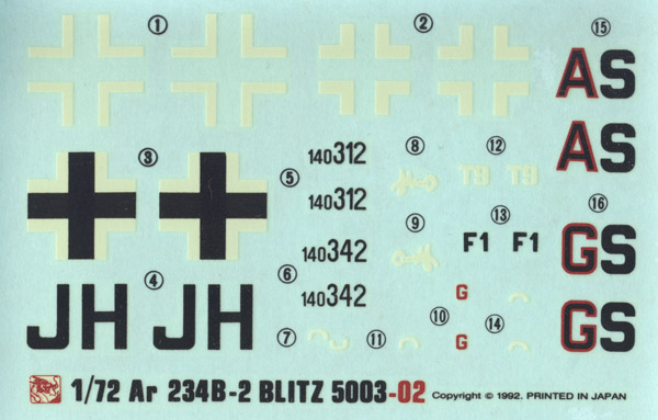
| The Dragon decal sheet is not very good. The printing looks childish in a way, perhaps because the items are printed rather 'fat', and because the white parts are cream instead of white. I will definitely not use them. I found four aftermarket decals sheets for the Dragon Arado 234B: Aeromaster 72-085 and 72-087, 'Arado 234 Blitz bombers part 1 and 2', Ventura V7263 'US and UK captured Ar 234', and a very nice set by Tally Ho (the Canadian Tally Ho, not the Czech one). All of these are discontinued as far as I know. I found Aeromaster sheet 72-087 and bought it, mainly to serve as a reference, and maybe for some stencils. In 2019, PrintScale issued a new decal sheet for the Ar 234B, with 11 options.
| 
|

| Most likely I will do prototype V10, the second B model, WNr 130010 (or even WNr 234130010), Stammkennzeichen PH+SR, using Alps decals. Shown here is the artwork, consisting of (top to bottom): two sets of fuselage codes, right lower wing code, left lower wing codes, upper wing crosses and WNr sets. The characters of the Stammkennzeichen are made from the 'Blockschrift für Flugzeuge' font (thanks Ronnie Olsthoorn for making the set!), but I made the characters some 15-20% fatter, and changed the height-width ratio slightly, to make them 60% high and 40% wide, using the cross size as reference. The size and spacing of the letter was done according to Luftwaffe instructions as reprinted in books by Merrick and Ullman. Underwing codes are not common on Ar 234's, but a photo of V9 shows that they were applied to the prototypes.
The font 'Placard Condensed' looked a lot like the WNr I found in a photo of WNr 130022, after widening it some 20-25%. But the WNr sets are probably not needed, I just can't see them on V9 and V10. Swastikas will be taken from an Xtradecal sheet. Possibly I will also design decals for the canopy riveting, but this will require some delicate measurements, to establish the correct curves for those on the front part of the canopy. I once tried fitting a straight narrow decal on a curved canopy frame, and concluded that such attempts are futile.
|
Here's a test fit of the decal design. I think it compares well with photos of V9 PH+SQ in the Monogram book. However that aircraft seems to have a Balkenkreuz with thicker legs - I have to look into German painting regulations again.
And indeed, my fuselage crosses were most likely wrong. Following Ullman page 132 (1943 iron cross regulations), the white legs should be 1/8th of the height, and mine were 1/10.67th of the height. How that ever happened I cannot reconstruct, 20+ years after designing the original set.
| 
|

| Luftfahrt LD21 'Arado 234 - der erste Strahlbomber der Welt', page 458, shows that V9 / PH-SQ had the Stammkennzeichen painted on the lower wing. I assumed that 'my' V10 / PH-SR followed that pattern. The underwing markings were also test-fitted on the model.
|
| I still need to design the cockpit boarding markings on the left front fuselage. Maybe that will also lead to an extended boarding ladder. I copied the section about the various hatches from the handbook.
| 
|
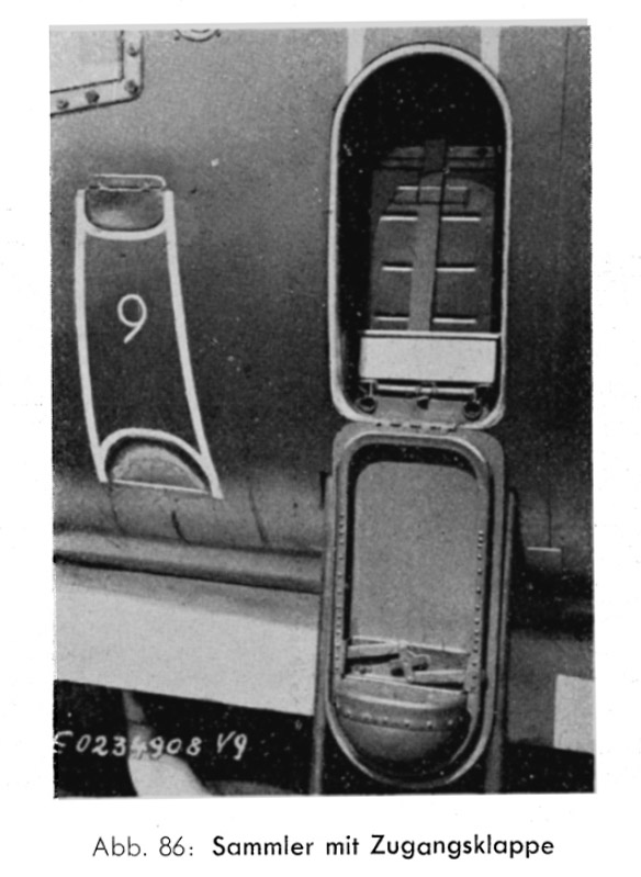
| The earliest B-models had more extensive line markings on the fuselage side, to aid in boarding the aircraft. The Versuchsnummer was painted inside the 'rectangle' (V-9 here). The battery hatch is open here. A foot is incorporated in the hatch's top side, that's now inverted and on the bottom side. I'm pretty sure it's closed before the pilot boards the aircraft, because there would be no 'third step' for the right foot.
The photo also shows the ladder extended, but you can only see the two tubes. I found another rare photo of the extended ladder on page 13 of 'Last days of the Luftwaffe' by Mafred Griehl.
|
Weapons
According to Flugzeug-Handbuch 8-234B-2, page 23, the centerline could take a 500 or 1000 kg bomb, the nacelles one 250 or 500 kg bomb each.
The kit contains a single SC1000 'Herman' bomb (Sprengbombe Cylindrisch - 1000 kg) with integral 'Kopfring' anti-ricochet ring, to be mounted on the centerline. According to OP 1666: German Explosive Ordnance (Volume 1) from June 1946, there were three versions: C (unspecified construction), L (tube steel construction), L2 (nose forged steel, body tube steel). Listed lengths and diameters are respectively 109.5" / 99.9" / 109.5" or 2781 / 2537 / 2781 mm and 26.0" / 25.5" / 25.6" or 660 / 648 / 650 mm. The kit's bomb measures 39 x 9 mm or 2800 x 650 mm in full size, quite OK for an SC1000-C or SC1000-L2.
In case I decide to display typical Arado 234 weapons, here's what is available:
SC500: Kora Models 72-129 and -130, CMK A7184
SC1000: Kora Models 72-227 (possibly 72-131) or DS7219 with 'Schlitten', CMK: A7185
Decals: Print Scale 72-057
maybe the bombs can be posed on sleds like these Transportgestell TG1 with SC500 Bombs by JK Resin
An interesting reference for bomb colors is this article by 'Grzesio': Colour markings of German bombs 1939-1945.
References
YouTube: Arado Ar 234 Blitz (1944) with PH+SR between 0:18 and 00:52.
'Luftfahrt Dokumente LD21: Arado 234 - der erste Strahlbomber der Welt' has 400 pages of original test flying documents. For V10 it lists most of the flights, starting with the 4th flight on 5 May 1944 (page 119), and ending with a crash during the 50th flight due to engine fire on 22 July 1944 (page 204). Also of interest is the use of V10 for a 'Vorführung' at Rechlin on 12 and 13 June 1944 (page 156).
NASM Ar 234B color discussion on the Hyperscale forum
Modeling links
I found only very few built Dragon 1/72 Arado 234Bs on the internet - most are 234Cs or what-ifs. Therefore one Lindberg and one Frog model are included too.
For reference, a few reports on 1/48 and 1/32 models:
The history of V10 / WNr 130010 / PH+SR
The book 'Arado Ar234 - Der erste Strahlbomber der Welt' by Luftfahrt Dokumente (issue LD21) contains an amazing set of original Arado documents. It contains (among others) 'Flugberichte' that detail individual flights during the development program. It allowed me to compile 96% of the fifty flights of V10 / WNr 130010 / PH+SR.
| Flight
| Date
| Pilot
| Purpose
| Ref.
|
| 1
| 7 April 1944
| Janssen (Arado)
| first flight
| PDF p9
|
| 2
| ?
| ?
| ?
|
|
| 3
| ?
| ?
| ?
|
|
| 4
| 5 May 1944
| Eheim (Arado)
| Climb and sink speeds in landing configuration
| p119, 121
|
| 5
| 6 May 1944
| Janssen (Arado)
| Diving from 9,000 to 5,000 m at 30 degrees, the aircraft reached Va = 780 km/h, with no Mach effects noted at all.
On page 103, it is reported that on 14 April 1944, V9 achieved Vw = 920 km/h in a dive at 4000 meters altitude, withouth encountering compressibilty effects (I calculate Mach 0.79).
Judging from pages 238-239 in 'Arado Ar234 - Der erste Strahlbomber der Welt', at least several S-aircraft (S for 'Serienbau' probably, built after 27 'Versuchs'-aircraft) with Werknummern in the 140xxx range, had two speed indicators. One gave 'Va' 'abgelesene Geschwindigkeit' without height compensation (nor calibrated, nor compensated for installation error) and 'Vw' 'Hohenkompensierter Fahrtmesser' with height correction (but not calibrated, nor compensated for installation error). The WNr 140009 speed data shows a maximum level speed at 6000 meters of Vw = 770 km/h. Others achieved Vw = 690, 700, 710 and 720 km/h, quite a spread. The higher speed of WNr 140009 was strange, as was also commented on by Arado engineers elsewhere in the book.
| p119
|
| 6
| 6 or 7 May 1944
| Eheim (Arado)
|
| p120, 126
|
| 7
| 9 May 1944
| Janssen (Arado)
| Formation flight with V9, endurance flight
| p126, 134
|
| 8
| 12 May 1944
| Lau (GdK)
| Evaluation flight
| p128
|
| 9
| 12 May 1944
| Lau (GdK)
| Evaluation flight
| p128
|
| 10
| 12 May 1944
| Eheim (Arado)
| Performance tests
| p129
|
| 11
| 12 May 1944
| Eheim (Arado)
| Performance tests
| p129
|
| 12
| 13 May 1944
| Eheim (Arado)
| Performance tests
| p129
|
| 13
| 17 May 1944
| Carl (Arado)
| Instruction / briefing flight
| p130
|
| 14
| 18 May 1944
| Eheim (Arado)
| Formation flight with V11
| p130, 134
|
| 15
| 20 May 1944
| Eheim (Arado)
| Maintenance test flight
| p132
|
| 16
| 21 May 1944
| Richter (Patin)
| 'Dreiachsensteuerung', most likely testing the 'Patin Dreiruder/Dreiachsen Steuerung' (PDS) three-axis autopilot)
| p132
|
| 17
| 21 May 1944
| Richter (Patin)
| 'Dreiachsensteuerung'
| p132
|
| 18
| 22 May 1944
| Richter (Patin)
| PDS calibration
| p132
|
| 19
| 23 May 1944
| Richter (Patin)
| PDS calibration
| p132
|
| 20
| 23 May 1944
| Zechner (Rechlin)
| Control comparison with V11 (that had different bearings)
| p132
|
| 21
| 23 May 1944
| Richter (Patin)
| PDS calibration
| p132
|
| 22
| 23 May 1944
| Richter (Patin)
| PDS calibration
| p132
|
| 23
| 24 May 1944
| Eheim (Arado)
| PDS evaluation
| p132
|
| 24
| 25 May 1944
| Richter (Patin)
| PDS
| p132
|
| 25
| 25 May 1944
| Richter (Patin)
| PDS work concluded, extremely satisfactory results
| p132
|
| 26
| 30 May 1944
| Eheim (Arado)
| PDS evaluation
| p133
|
| 27
| 31 May 1944
| Kröger (Arado)
| ?
| p133
|
| 28
| 31 May 1944
| Zechner (Rechlin)
| PDS evaluation
| p133
|
| 29
| 1 June 1944
| Kröger (Arado)
| Stability tests, interrupted by a tire blowing in flight
| p149
|
| 30
| 6 June 1944
| Eheim (Arado)
| Maintenance flight test ?
| p155
|
| 31
| 7 June 1944
| Kröger (Arado)
| Stability tests. Grounded afterwards because of landing gear door rods that are too weak.
| p155
|
| 32
| 7 June 1944
| Eheim (Arado)
| Stronger landing gear door rods fitted. Demonstration flight training.
| p155
|
| 33
| 10 June 1944
| Eheim (Arado)
| Transfer flight from Alt-Lönnewitz to Rechlin-Lärz
| p159
|
| 34
| 12 June 1944
| Eheim (Arado)
| Demonstration flight at Rechlin-Lärz. Low-level pass at 820 km/h, pull-up to 2,000 m, etc.
| p156-159
|
| 35
| 13 June 1944
| Eheim (Arado)
| Demonstration flight at Rechlin-Lärz. Low-level pass at 820 km/h, pull-up to 2,000 m, etc.
| p156-159
|
| 36
| 13 June 1944
| Eheim (Arado)
| Milch was so impressed that he ordered an ad-hoc turning performance fly-off with the Me 262, during which Ar 234 proved to be the best in a turning fight. The Me 262 however could escape using breakaway manoeuvers. The Ar 234 had some rivet damage on the lower wing side afterwards
| p156-159
|
| 37
| 13 June 1944
| Eheim (Arado)
| Transfer flight from Rechlin-Lärz to Alt-Lönnewitz
| p159
|
| 38
| 21 June 1944
| Eheim (Arado)
| Maintenance flight test ?
| p171
|
| 39
| 21 June 1944
| Meister
| Evaluation flight, braking criticism
| p171
|
| 40
| 21 June 1944
| Thierfelder
| Evaluation flight
| p172
|
| 41
| 23 June 1944
| Eheim (Arado)
| Demo similar to the Rechlin one
| p170
|
| 42
| 24 June 1944
| Kröger (Arado)
| Stability test flight
| p170
|
| 43
| 12 July 1944
| Eheim (Arado)
| PDS flight
| p201
|
| 44
| 13 July 1944
| Schilling
| Training / introduction flight
| p201
|
| 45
| 17 July 1944
| Eheim (Arado)
| PDS adjustment
| p201
|
| 46
| 17 July 1944
| Schilling
| Simulated attack profiles
| p201
|
| 47
| 18 July 1944
| Schilling
| Maintenance flight test ?
| p201
|
| 48
| 18 July 1944
| Storp
| Simulated attack profiles
| p201
|
| 49
| 21 July 1944
| Richter (Patin)
| PDS adjustment
| p202
|
| 50
| 22 July 1944
| Richter (Patin)
| Test flight for the 'PDS-Steuerung' autopilot. Take-off from Alt-Lönnewitz. Problems with left engine, shut down, but very high temperature indicated - fire was suspected. Pilot jumped and landed safely. Aircraft crash-landed near Bortewitz after continued banked flight, relatively intact, but fire broke out after 15-30 minutes.
| p204-205, 213
|
Return to models page


