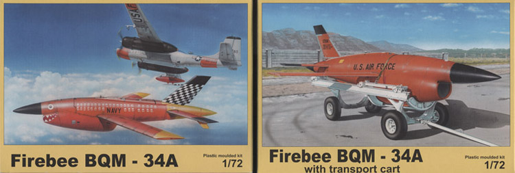
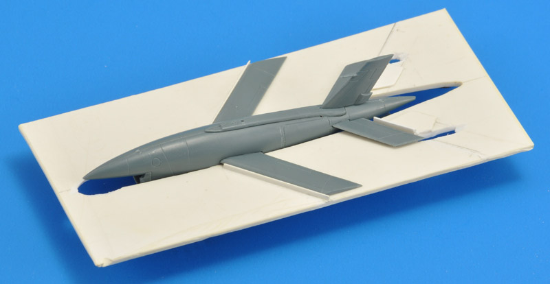
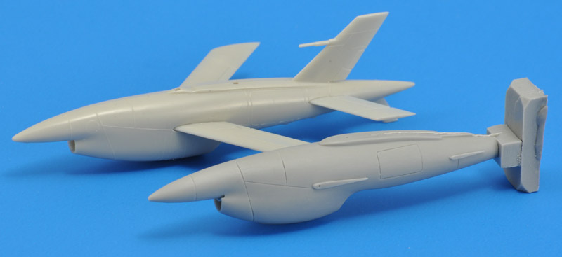
The box art of kit 7028 shows a Navy Firebee just after the drop from an Air Force DB-26B, which is a bit silly. This box contains two Firebees plus various pylons. The box art of kit 7035 shows an Air Force Firebee on an Air Logistics 3000 trailer. This kit contains one Firebee plus the trailer in resin. Both box arts have one thing in common: the kit inside does not completely represent the Firebee shown. More on that in the review.
the Firebee family started with the smaller Q-2A (USAF) aka KDA (Navy) aka M-21 (Army)
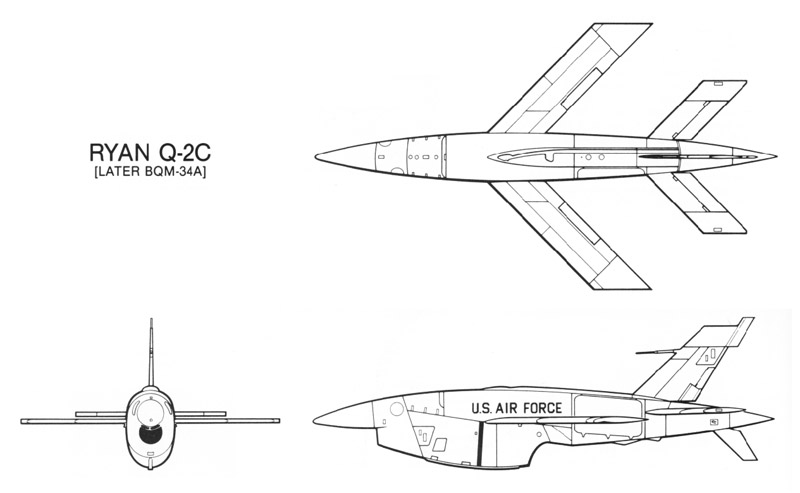
the second-generation Firebee as discussed here first flew in March 1960, then called Q-2C (USAF and strangely Navy too), 124E (Army), and Model 124 by the factory. It had the Continental J69-T-29 (1700 lbs)
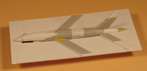
I think that the first batch(es) had no ground-launch capability. In that case there was no JATO rocket attachment bracket under the rear fuselage, no JATO collar attachment brackets on the parachute cone, and no 'slider' brackets under the wing
in 1961 (William Tell exercise), zero-length ground-launch was introduced. Navy followed late 1962
in 1962 the designations were standardized under the 'Tri-Service System' to BQM-34A for USAF and Navy, and MQM-34D for the Army. All missiles got a three-letter designation that is decoded as follows:
B stands for 'multiple launch methods'. M stands for 'mobile launcher'
Q stands for 'pilotless drone'
M stands for 'missile'
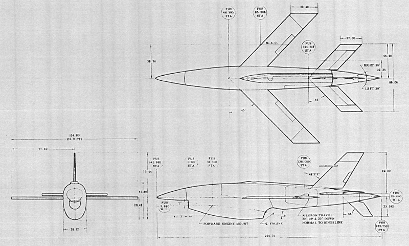
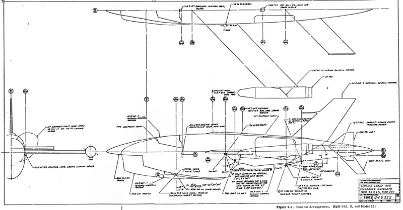
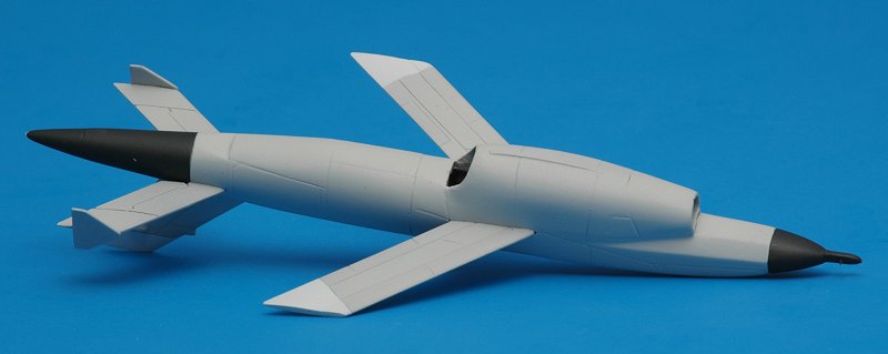
in 1973 the General Electric J85-GE-7 (2450 lbs) was installed in a special model for the Army (Model 251) with a blunt 'bottle' nose, called 'MQM-34D Mod II'. It is shown below in the third reference drawing, but otherwise ignored in this review
starting 1983, the J85-GE-7 replaced the J69 in some Navy versions. The Navy started using the designation BQM-34S the eighties. It's not clear to me what exactly makes an 'S', since it was ordered with both the J85-GE-7 and the uprated J69-T-41 (1920 lbs). Also, normally the designation 'BQM-34A' would be followed by 'BQM-34B', so the 'S' is probably short for the feature that makes this version so different
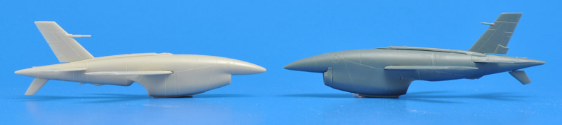
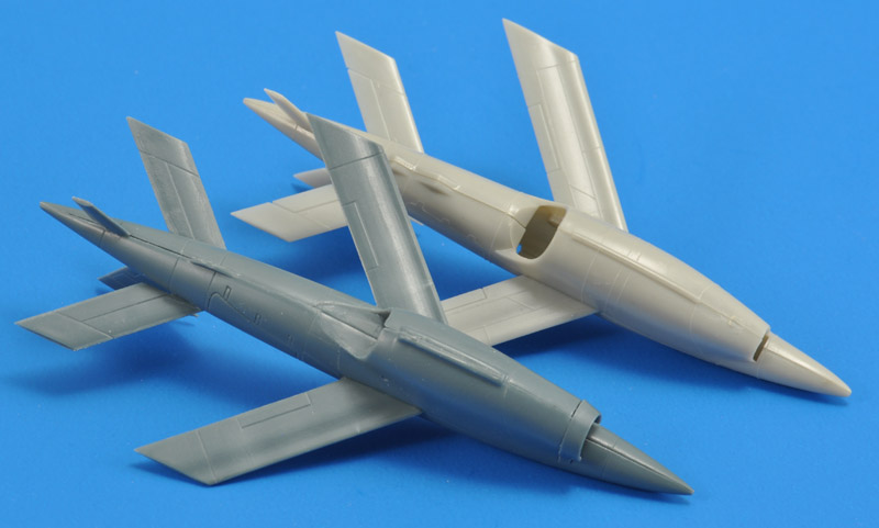
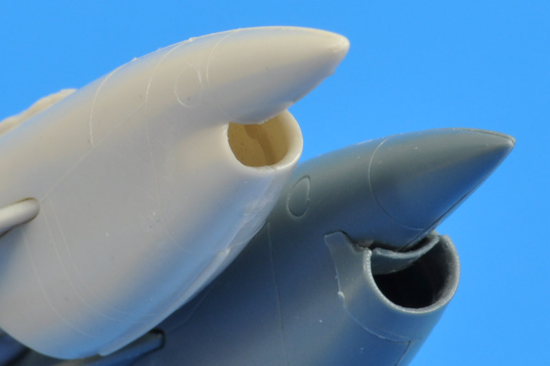
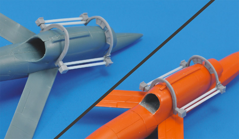
starting 1989, the J85-GE-7 replaced the J69 in the USAF versions. The USAF retained the BQM-34A designation. As far as I can tell, the J85 version of the BQM-34A uses the same nacelle as the original version with the J69 engine. However, the inlet was enlarged, basically by cutting back the front end of the nacelle. This is easy to spot, since the inlet is now some distance behind the radome. The radome was tilted up, and now points straight forward instead of a couple of degrees down.
I'm not looking for 100% dimensional accuracy, but the kit dimensions are an indication whether the CAD designer / mold maker did his homework, and/or had decent reference material. All three available BQM-34A (Q-2C) Firebee models were analysed.
|
| Ryan data
| SI units
| Italeri
| Black Dog
| PlusModel
| Comments
|
|
| source
| unit
| mm (1/1)
| mm (1/72)
| mm
| diff.
| mm
| diff.
| mm
| diff.
|
|
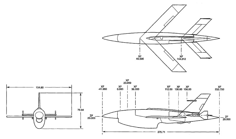
| Fuselage length drawing 1
| FS -41.960 to
FS 233.750
| 275.71 in
| 7003
| 97.3
| 96.2
| -1.1%
| 80.9+10.5=
91.4
| -6.1%
| 100.6
| +3.4%
|
|
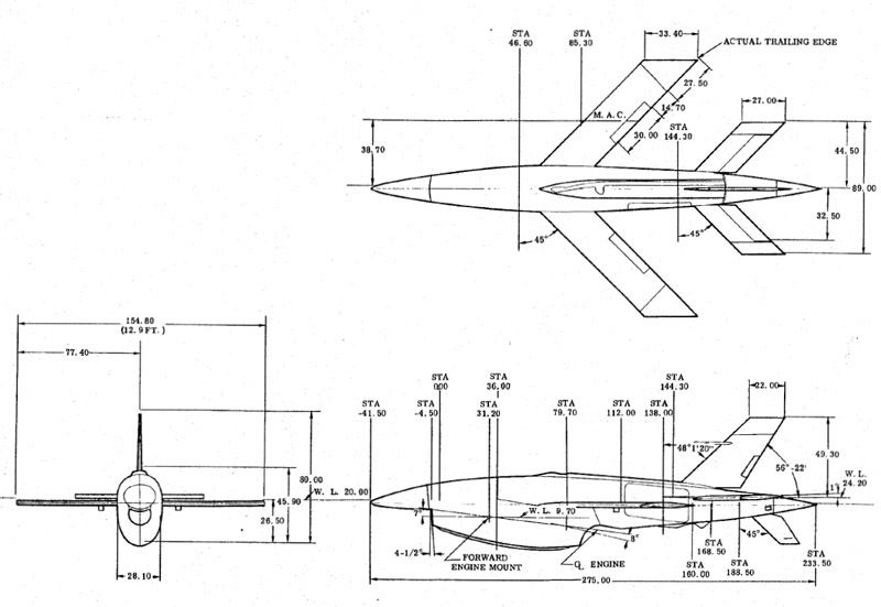
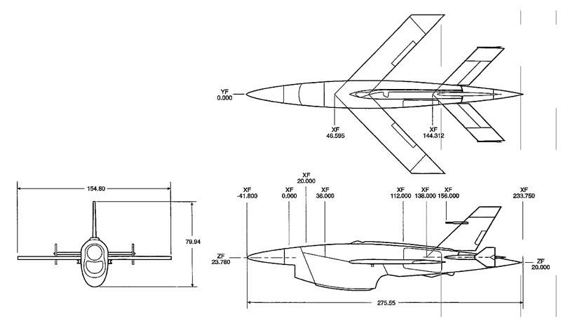
| Fuselage length drawing 2
| FS -41.5 to
FS 233.750
| 275.25 in
| 6991
| 97.1
| 96.2
| -1.0%
| 80.9+10.5=
91.4
| -5.9%
| 100.6
| +3.6%
|
|
| Fuselage width
|
| 28.12 in
| 714
| 9.9
| 10.7
| +4.8%
| 12.3
| +24%
| 11.4
| +15%
| Drawing 2 shows 28.10 instead of 28.12. The difference is 0.5 mm in 1/1 scale and therefore ignored.
|
| Fuselage height
|
| 45.89 in
| 1166
| 16.2
| 17.3
| +6.7%
| 19.2
| +18.5%
| 20.2
| +24.5%
| Ryan measurement could be excluding the skid and spine cover; model measurements are including these
Drawing 2 shows 45.90 instead of 45.89. The difference is 0.25 mm in 1/1 scale and therefore ignored.
|
| Wing span
|
| 154.80 in
| 3932
| 54.6
| 56.1
| +2.7%
| 57.7 *
| +5.7%
| 55.9
| +2.4%
| * summed widths: 2 * cos45 * 31.4 + 13.3
|
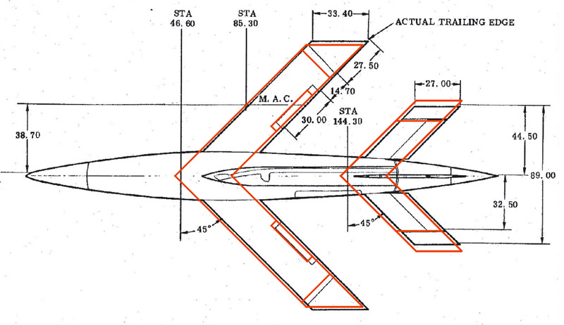
| Wing chord (perp. LE)
| 33.40 * cos45
| 23.62 in
| 600
| 8.3
| 8.9
| +6.8%
| 8.8
| +6.0%
| 8.7
| +4.4%
|
|
| Hor. tail span
|
| 89.00 in
| 2261
| 31.4
| 31.7
| +1.0%
| 33.9 **
| +8.1%
| 35.0 *
| +11.5%
| * when mounted at 45 degree sweep
** summed widths: 2 * cos45 * 17 (av) + 9.9
|
| Hor. tail chord (perp. LE)
| 27.00 * cos45
| 19.09 in
| 485
| 6.7
| 7.0
| +4.5%
| 6.8
| +1.5%
| 6.8
| +1.5%
|
|
| Vert. tail LE sweep
| 48°1'20"
| 48.02 deg
|
|
| ~47 deg
|
|
|
| ~45 deg
|
| note that the first drawing shown lists 48'1'2" instead of 48'1'20"
|
| Vert. tail TE sweep
| 90 - 56°22'
| 33.63 deg
|
|
| ~32 deg
|
|
|
| ~26 deg
|
|
|
| Vert. tail tip chord
|
| 22.00 in
| 559
| 7.8
|
|
|
|
|
|
|
|
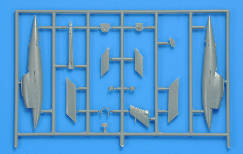
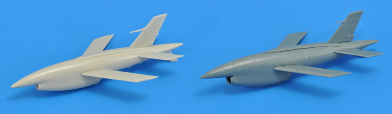
quite a few major panel lines are in the wrong places:
on the front fuselage, the canted panel line is ~4 mm to far back
on the rear fuselage, the line behind and above the torsion box of the horizontal tail should be canted towards the rear. This in turn gives more room for the vertical tail to connect to the fuselage
on the vertical tail, the front panel line is parallel to the leading edge, but it shouldn't
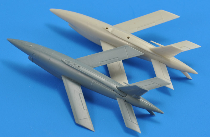
compared to the last drawing in the 'reference drawings' section, many of the minor panel lines on the front fuselage are absent. Italeri did the same. One could also say the scale is too small for these details.
the wings look a bit bare with just engraved lines for the aileron and tip cap. I like them better with more details like Italeri, but those are raised
the balance weights of the elevators are missing
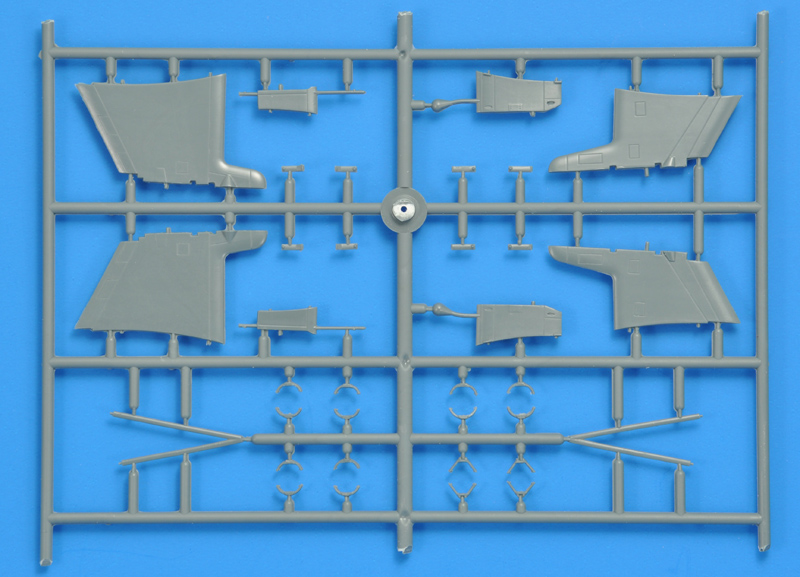
the skid is far too wide, and too short on the front side
the recessed attachment point for the trailer on the rear fuselage is missing. Italeri has a 'rubber bumper' there
the attachment points for the JATO collar on the main chute cover are absent. See for example this BQM-34 photo. Location is probably FS 196.7x and WL 18.3x (?)
too much of the root of the vertical tail is cut away where it meets the fuselage. The gap should reduced in length by ~2 mm.
the pitot tube is way too short, and it points too much upwards
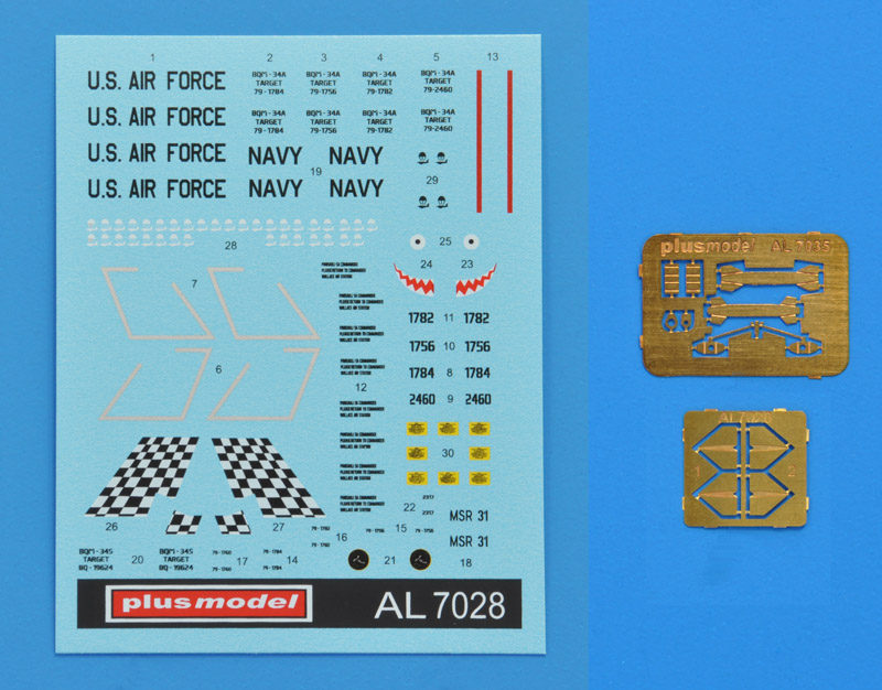
Both kits (7028 and 7035) share the same decal sheet, that has three decal options. It's a pity that PlusModel does not provide their backgrounds. Luckily I was able to find most of the details:
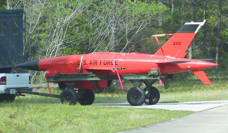
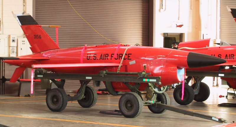
Four almost identical USAF Firebees as used at the Wallace Drone Launch Facility in the Phillipines, part of US Pacific Air Forces, around 1984-1985. Serial numbers of the decals provided are 79-1756, 79-1782, 79-1784 and 79-2460. These four Firebees are visible in a row in USAF photo 'DF-ST-85-11964' and other photos made on the same occasion. Also see this NARA 'Wallace Air Station' photo search. The vertical tails are outlined in white or light gray (decals are silverish). Maybe it is reflective tape to make sea recovery in the dark easier.
The instruction tell you to use 'glossy insignia red' (i.e. FS 11136), however the USAF orders from the time specificy FS 12197 International Orange. And judging from the photos linked above, the Wallace Firebees had a yellow-ish variant of this color, more like FS 12473. Either they were painted as such in this production batch, or the scorching Philipinne sun changed the original color.
Decals for the text 'PAKISAULI SA COMMANDER / PLEASE RETURN TO COMMANDER / WALLACE AIR STATION' are provided, but not included is the text on main parachute cone: 'WARNING / EXPLOSIVE SQUIBS INSTALLED / HANDLE IAW AFR 127-100' in white or black. There are also repetitions of the 'last four' on the airframe, that are not included.
YouTube has two San Diego Air and Space Museum videos showing operations at Wallace Air Station: F 1180 Ryan Aeronautical Firebee Drone Wallace/Phillipines and F 3422 Wallace Air Force Base Ryan BQM-34 Firebee Launches (1968), showing both Air Force and Navy Firebees.
USN Firebee, as on display at the Estrella Warbirds Museum. Originally it was all white with a black radome and fin tip. It was restored with similar markings, but painted orange overall. In 2017 it was repainted white overall with the same markings, closely resembling the way it arrived at the museum. However, Craig Kaston provided photos from 2008 made at Edwards, and there it showed an extremely faded dayglow orange over a white, and several more coats of paint under that. Some original orange remained under service marking stickers that were slowly peeling off. So it probably was dayglow orange at the end of its service life.
I keep seeing 'something' in the radome, it looks like its 'stance' is halfway the downturned one of the original Firebee, and the 'straight forward' one of later versions. However it seems that it originally was a 'downturned' radome. The round badge lacks the text 'MOBILE SEA RANGE' (MSR) and other details. MSR-31 should be a stencil type font. Left side mission markers on the vertical tail should point to the rear.
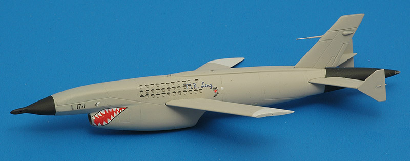
USN Firebee of the Target Department of the Aerospace Operations Department of the Naval Missile Center, Point Mugu, 1963-1964. It has a checkers tail, sort of a shark-mouth and eyes. A black & white photo is shown in the magazine 'Ryan Reporter' from Spring 1964 (p7, PDF p311), similarly in 'Fireflies and other UAVs' (p80). It survived 34 or 36 missions according to the captions, and the decal shows 36 mission markers. The identity is painted on the nose, but it is very difficult to read due to the small size of the photo - I see something like 2311, 2313, 2315 or 2317. Flickr has an in-flight photo with 36 mission markers, but no visible identity. The box art is a straight copy of this photo. Alamy has an flight line photo but no visible identity.
The instruction tell you to use 'glossy insignia red' (i.e. FS 11136), and although we only have black & white photos to judge things, this color is unlikely. US Navy drone color specs are not 100% clear, but it seems that the Navy used FS 11136 Insignia Red for drones from 1946 to 1959, and FS 28915 Fluorescent Yellow-Orange after that. However FS 12197 International Orange and FS 17925 Insignia White is also specified for drones. Since the Q-2C/BQM-34 is from 1960 and later, FS 11136 Insignia Red is unlikely. That leaves FS 28915 Fluorescent Yellow-Orange and FS 12197 International Orange. The Navy color transition is visible in this undated F-2438 Ryan Firebee Maintenance video, that shows red, orange and white Navy KDA-4s. Note that the freshly delivered ones are orange.
Just maybe it's also shown in Ryan Reporter, May/June 1962 issue (p32, PDF p100). Its identity is 2317, marked as 'KD-7358 / Q-2C59-2317' on the data block. Unlikely: it has 'U.S. NAVY' instead of 'NAVY' titles. "A Ryan Firebee, flown by the Aerospace Operations Department at the Naval Missile Center, Pt. Mugu, was recently the victim of an interesting numbers game. Engine mechanics, checking the Firebee serial numbered "2317", after a recent mission noted that the engine time had been clocked at exactly 23 hours and 17 minutes and that the drone—affectionately called "Bessie" had completed its 17th hop on the Pacific Missile Range. In honor of the occasion, Pt. Mugu civilian employees Ray Hardquist (left) and George Peterson (right) strategically place a decal indicating the 17th flight."
Missing from the decal sheet are 'DRONE' stencils for USAF Firebees and 'TARGET' stencils for Navy Firebees. Also missing are small white dot decals, maybe white stickers to 'seal' inspected hatches. The later are easily made with a little paint on a needle point.
Note that all decal options are for the original J69 version with the downturned radome.
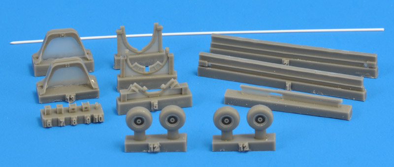
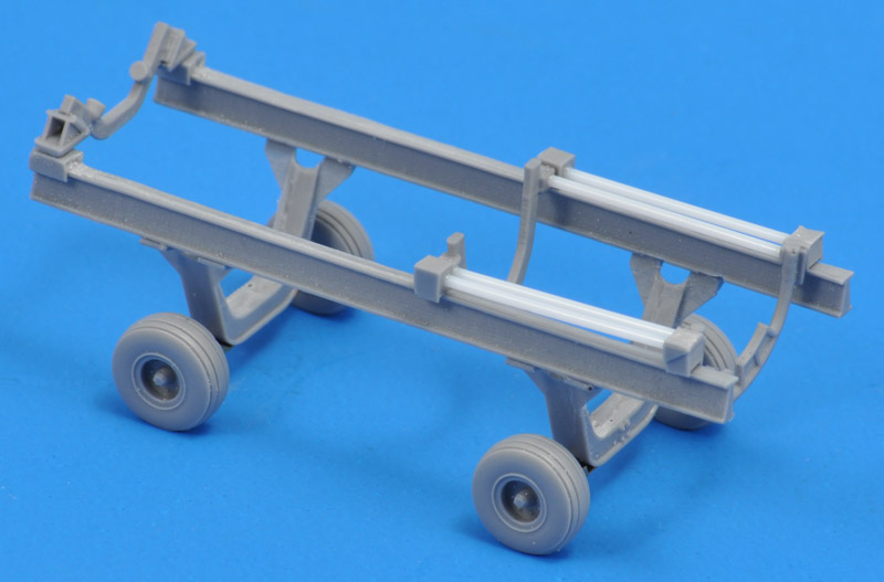
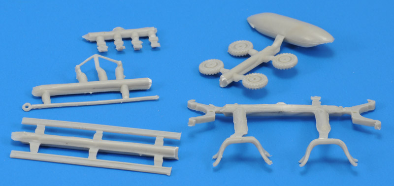
By taking measurements of the built-up trailer, I could see what Air Logistics 3000-series type it tried to represent. My reference was this great Air Logistics Corporation Ground Support Catalog 1980 brochure. From the 3000A through J versies, the combination of rail length and height only left the 3000A, E or G types. The G type drops out because it had steerable rear wheels. The A and E appear to be largely identical, but the E is lighter, possibly due to material differences. My conclusion is that the kit represent either the 3000A or 3000E. We can then compare the measurements of the model and Air Logistics data.
|
| Plusmodel
| Air Logistics
3000A or E
| Modification
|
|
| mm 1/72
| mm 1/1
| inch 1/1
| inch (1/1)
|
|
| Rail length
| 57.3
| 4126
| 162.4"
| 152.0"
| 3.7 mm decrease, easy to do
|
| Rail spacing
| 18.2
| 1310
| 51.6"
| 48.0"
| 1.3 mm decrease, modification not recommended
|
| Rail height
| 17.0
| 1224
| 48.2"
| 40.0"
| 2.9 mm decrease, would improve looks much
|
| Wheel base
| 30.1
| 2160
| 85.0"
| 92"
| 2.7 mm increase, recommended
|
| Wheel track
| 22.0
| 1584
| 62.4" #
| 50"
| 4.4 mm decrease, recommended (# based on my build with steel axles)
|
| Tire diameter
| 8.7
| 626
| 24.7"
| 7.5x10
| 10 + 2*7.5 = 25", near perfect
|