RealSpace 1/96 Apollo Command & Service Module


For the 2019 IPMS-NL Euro Scale Modeling show, our club (IPMS-NL Regio Zuid-Holland) decided to build a '50 years Apollo 11' stand. It would display six stages of the mission, all in 1/96 scale. I picked the stage where the CSM plus LM circled the moon. Thus I started building the RealSpace 1/96 Command & Service Module combined with the Revell 1/96 Lunar Module. This page covers the CSM.


Kit description

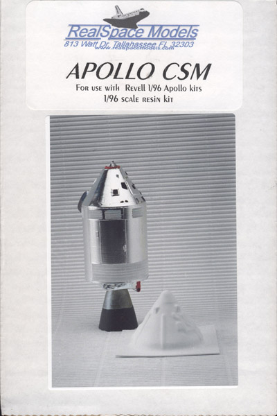
The RealSpace 1/96 kit replaces the Revell 1/96 CSM that represents a Block 1 version instead of the Block 2 version of Apollo 11. They have very different detailing on the exterior, so the Revell model is really not suited to represent the Apollo 11 mission.

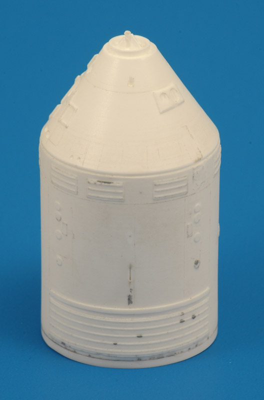
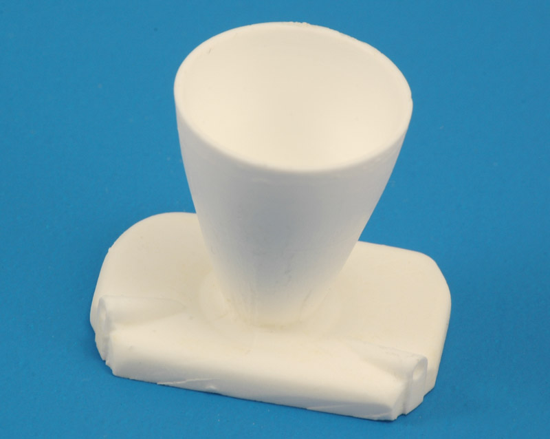
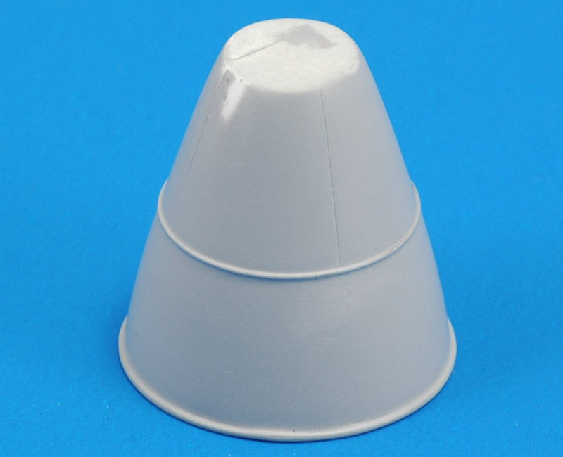
The kit contains a solid resin main body, the master of which appears to be turned, and the turning marks do become visible when you paint it with metallic paints. The other two resin parts are a combined rocket nozzle plus heat shield, and the umbilical cover. A vacformed part is also included, the Boost Protective Cover. The part listing shows that the RCS nozzles, the mast with parabolic antennas and the decals are not included. The resin parts were cast without vacuum or pressure, and they contain numerous small air bubbles. That makes for a laborious clean-up, as you will see. My example also appeared to be 'short-shot', it was 2 mm too short, stopping right behind the large radiators. Also, the 'scimitar antennas' were broken off from the SM body.

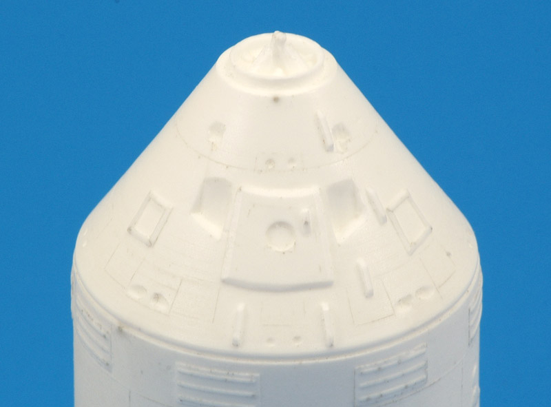
Regarding accuracy, I think overall the accuracy is pretty good. But I was disappointed to see some errors introduced. The main error that jumped at me is the raised entrance hatch of the Command Module. The slanted roll control thruster openings are badly defined, as are the four connections for the escape tower.

All in all I was a bit disappointed. The master model should be cleaned up, the casting should be improved, and extra parts should be supplied. Then it would be a fine kit.


CSM construction

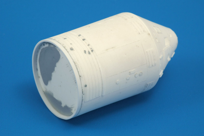
Compared to drawings, the solid resin part lacked 2 mm in length. Maybe RealSpace did not fill the mold completely? Or the part with the Service Propulsion System (SPS) was cast incompletely (see a couple of photos down), that's what the instructions suggest, but I am not really sure. The lengthening was done with a strip of 2 x 1 mm, pre-curved around a knife handle.
The casting showed numerous small pinholes and other small molding defects. This kit could be much improved with either vacuum or pressure casting. Initially I started filling the pinholes with liquid Mr Surfacer, but that did not work well. CA glue turned out be a much better filler.
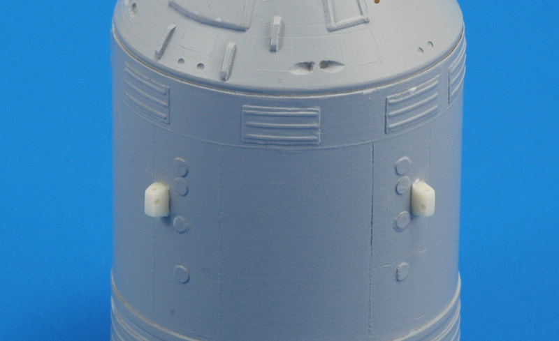
It's the same story on the other side. The 'scimitar antenna' on either side (in the centerline of this view) had broken off. I engraved a small slot, and cut 3 mm discs with a Waldron punch & die set to replace them.
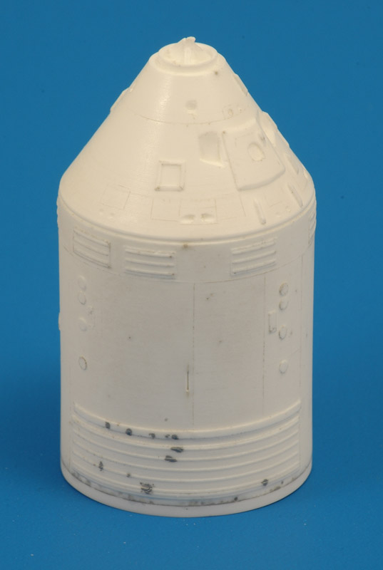
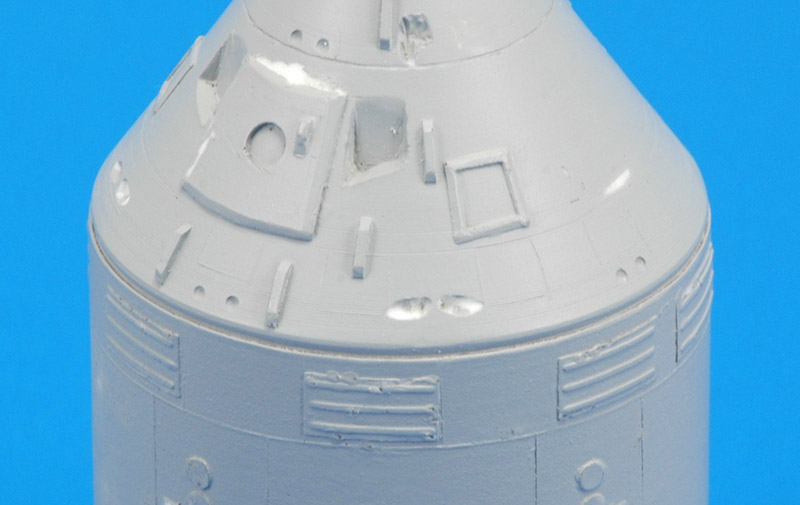
The detail on the Command Module required some attention, it's all a bit rough, not quite up to modern standards. Again there were pinhole air bubbles.

Only much later I concluded that the raised hatch is not correct, but by then it was too late to correct it. I can't understand why the master builder introduced this mistake.
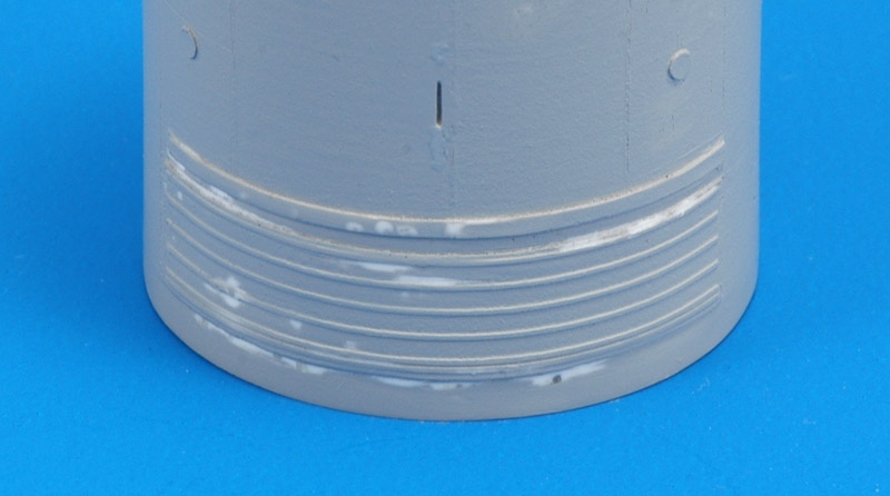
The rocket engine and the heat shield were quite horrible, very rough with lots of casting defects in the nozzle. The engraved lines on the heat shield were close to invisible. I decided the easiest solution would be to cut off the nozzle, sand it smooth, and clean up the heat shield with new engraved lines.
After I separated the nozzle from the base plate with a JLC saw, I sanded it down aggressively to make it smooth again. In that process I found hundreds of surface air bubbles, the nasty kind. I poked each one with a pointy blade and filled it with CA glue. Next I painted a layer of liquid Mr Surfacer 500, and sanded it down to fill the pinholes and larger depressions of the part. This is definitely the worst part of the kit.

I re-engraved the scribed line halfway the nozzle, and used it to position an 0.3 mm steel wire, some of sort of stiffener ring on the real thing. Similarly I glued a square 0.5 x 0.5 mm plastic strip around the end of the nozzle. These modifications are based on what I saw in photos of the real engine.

The first coat of spray can Mr Surfacer 1200 revealed about two dozen more air bubbles, that I filled with CA glue and sanded smooth again. The end result is still not 100% smooth, but it will do.
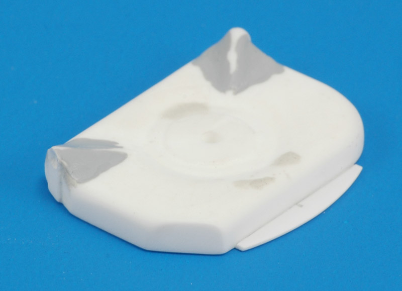
The heat shield required a lot of sanding and scraping to achieve a somewhat decent shape. Some scratches were filled with CA glue, and Apoxie was used to fair the two 'bulges' in with a bigger radius, and to fill some larger dents. Lastly I added a 0.5 mm plastic card piece (right bottom side of the photo) that I saw in photos.
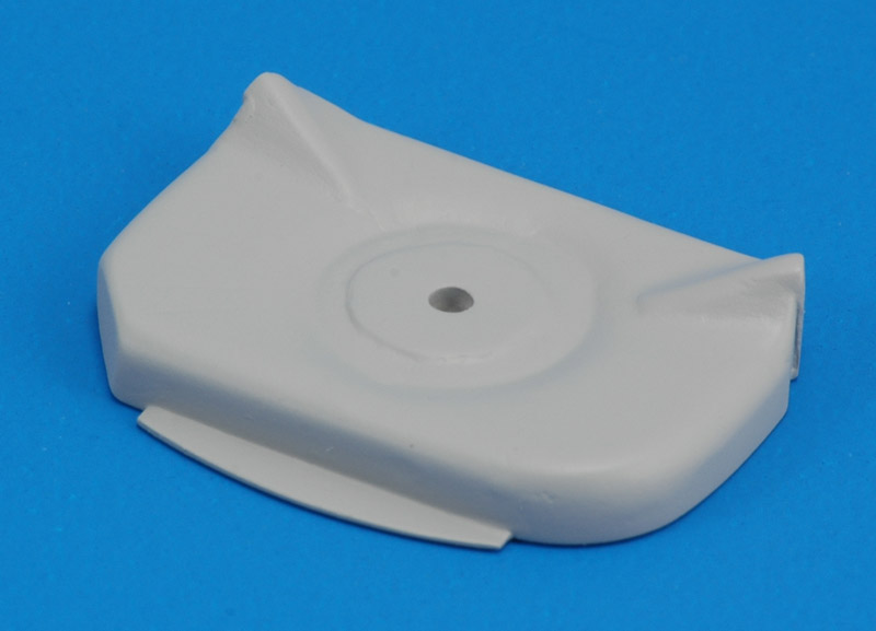
I coated the part with Mr Surfacer 1200 to see how far I had gotten with the rebuild. Unfortunately I could not think of a method to represent the raised circular and radial beads seen on this part. It was vaguely represented with incomplete engraved lines on the original part. This is quite a big omission, and I wasn't happy with the decision to leave them off.
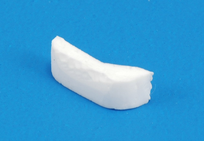
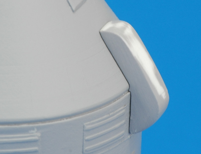
The worst-cast part is definitely the umbilical cover. It's very incomplete, with rough edges and doesn't fit flush on the model. I've done quite a bit of resin casting myself, but I cannot see how you can produce a part with so many defects.
Here's the same part after a total rebuild with Apoxie, and partially coated with Mr Surfacer 1200.
After correcting numerous small defects on the main casting, I sprayed it with Mr Surfacer 1200. That revealed about 50-60 more air bubbles, especially in the radiators, grrrrr.. The lengthening on the rear (or bottom) side was successful, the transition was invisible. Shown here is the result of lots of subtle sanding and scraping of the filled air bubbles.
More CA-filled air bubbles can be seen in the upper (smaller) radiators, that still need to be sanded down. The details on the Command Module also required more attention.

Not documented with photos are some more improvements of the Command Module details. The four holes for the Launch Escape System were quite ridiculous, like someone poked around a bit with the tip of a knife. One of these is seen at the very top of the photo, in the center. By accident I discovered a great technique to create much nicer 'longitudinal' holes (in the flight direction of the CSM). I first tried drilling at an angle into the CSM, but of course that would not work. Then I found out that the other end worked perfectly as a scraper, so I used that.

The same technique was used to improve the oval-shaped pitch/yaw/roll nozzles. They looked too small to me, and angled the wrong way ('down'). I changed them to larger oval openings in a circumferential direction. Later I discovered they should be angled 'upwards'. These improvements can be seen in later photos.
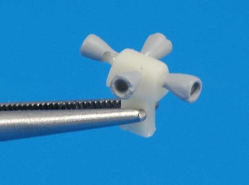
I made a (tiny) master for the RCS box, a tapered rectangle, based on NASA dimensions. It's a bit taller than the Revell one, and a bit shorter. I give the lateral RCS nozzles the correct small vertical offset, one of the errors of the Revell part. I cast copies of the box and added four of them to the Service Module.

This 3D printed 1/6th & 1/12th CSM RCS shows the full details of the RCS cluster, that I could not copy fully for the 1/96 version.
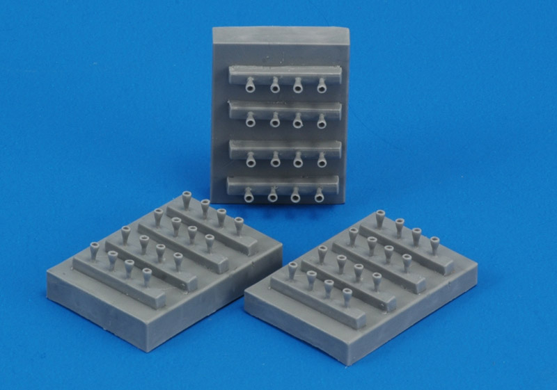
It turned out that the Revell RCS nozzles were mostly of the correct size. I used the best ones from the kit, opened them up with an 0.9 mm drill, which improved their appearance greatly. I selected four for resin reproduction, in sixteen-fold. The nozzle edges seemed just too thin for safe reproduction, and I solved that by spraying a few light coats of Mr Surfacer of my 'inter-masters'. Then I cast another mold of this set of sixteen thrusters.
I used four discarded RCS thruster castings, with a tiny air bubble and rough edges, to make a prototype of the RCS cluster.
The resin parts were given a black enamel base coat (Revell 9) that was heat cured to make it stick well to the resin. Next I painted most of the CSM with MRP-99 'US Navy White', an off-white color, for the cooling radiators.

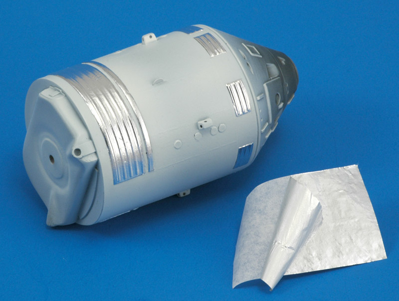
Next the radiators were masked with Cheap Chocolate Foil. With this ultra-thin masking material the 'sides' of the radiators can be masked too, which would be impossible with masking tape. I cut the CCF with a fresh scalpel blade, but it wasn't easy because of the irregularities in the casting. What you see now is sort of reversed colors, aluminium radiators and a white body :-)

On the heat shield at the back of the CM, you can see the added detailing of the cut-off corner, the top one in this view.
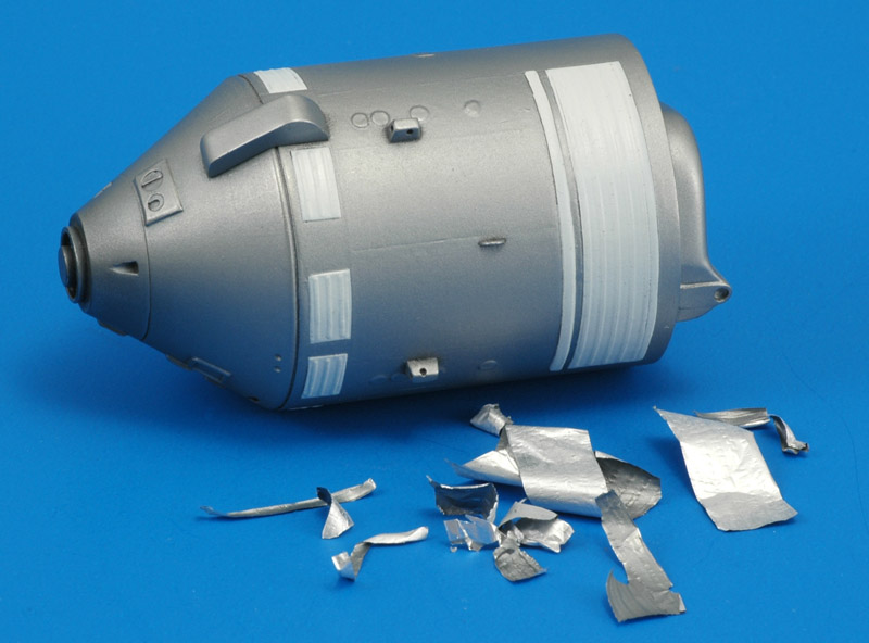
For our club project we decided to use Metalizer Stainless Steel for the body of the CSM. This looked most like the color of the transparent Teflon painted aluminium on the inside, that covered the Service Module. It doesn't look like bare aluminium, but still sort-of aluminium, just like the real thing. And here's what it looks like with the CCF peeled off.
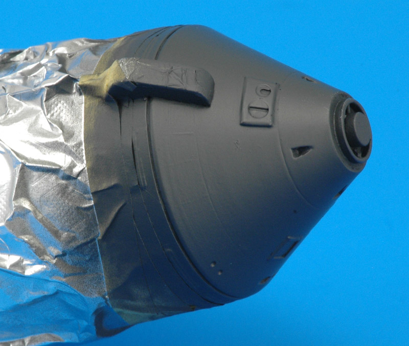
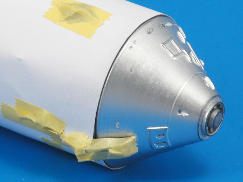
We decided to use Alclad Chrome for the Command Module, to represent the chrome-colored Mylar tapes applied to the CM exterior. It's a compromise because of the scale. I first made test pieces with a base coat of Revell 9 charcoal enamel and Vallejo 71.057 Black acrylic paint. To me eye, the acrylic base coat resulted in a bit less 'grain' in the Alclad Chrome, so I decided to use the Vallejo base coat. Fingers crossed that I will not have adhesion problems, since I'm not very familiar with Vallejo paint.

Prophetic words: the layer of black Vallejo had some drips in it, unacceptable under a chrome paint. I stripped the CM of paint again and started over, now using Revell 9, a paint that I am far more familiar with.
I used CCF to mask the Service Module, because the Metalizer could be vulnerable to stronger masking materials. The remainder was wrapped with kitchen aluminum foil.

After painting the Command Module I repeated the procedure for the heat shield on the rear. I'm not sure the real thing was 'chrome' like the CM, but it was pretty shiny, so Alclad Chrome it was.
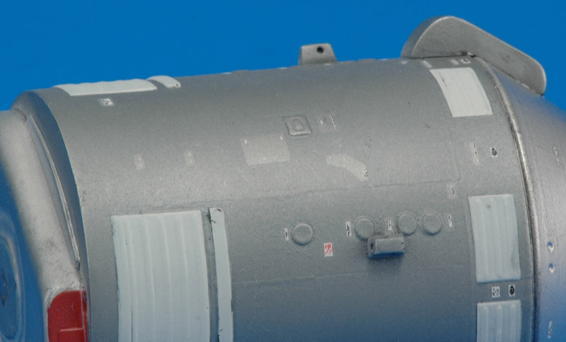
I applied the Space Model Systems decals (SMS-AP96) without testing, and that was a mistake. Apparently Metalizer Stainless Steel is not smooth enough to prevent silvering, so silvering I got after a clear coat. It wasn't full-blown silvering, under most angles it is not visible. But in this photo it is very visible.
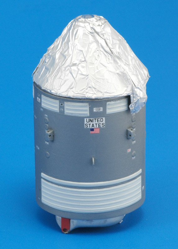
I used a 'tin foil hat' to mask the Command Module for the last clear coat on the Service Module. I used Alclad ALC-314 'Klear Kote Flat' to match the sheen of Metalizer Stainless Steel. It also created a nice visual difference with the Command Module that was much glossier.
On the Alclad Chrome-painted Command Module, either the water, or the water plus decal glue, or the tiny bit of Future created gray stains. Therefore I had to retouch the Alclad Chrome-painted Command Module after decaling. I used a quick paper mask to protect the Service Module.
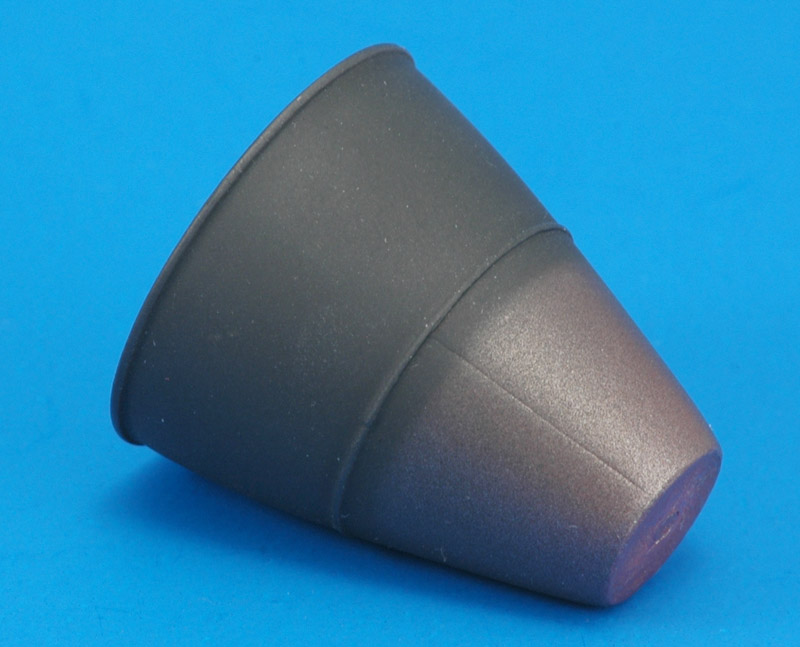
The CSM nozzle was first painted MRP-299 Insignia Red, followed by MRP-30 Steel, leaving the small diameter end redder than the rest. Next I used Revell 9 coal black to paint the interior and the large diameter half of the exterior. Since the Steel part was rather shiny, and contrasted too much, I dusted the R9 also over this part. The result was nice I think.
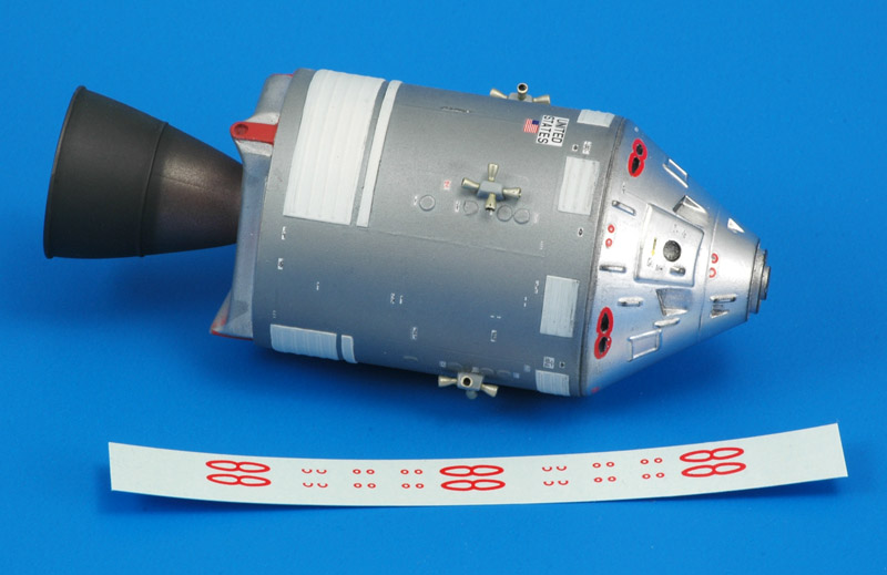
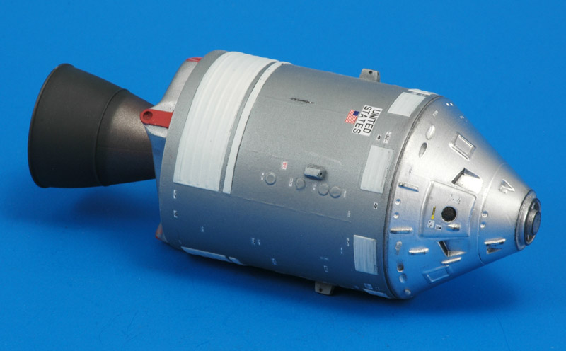
Here's the 90% finished model, only lacking the sixteen RCS nozzles, the four parabolic antennas on a stick, and some red decals on the Command Module. I can't say I am 100% happy with the results, but the club project's planning forced me to continue with what I have.

New in this photo is that I painted three details on the rear side's heat shield dull read, using MRP-299 Insignia Red with a little MRP-103 FS 30219. The masking with Cheap Chocolate Foil was difficult, leaving some traces of red in places where I did not want it. I'm not totally happy with the color, the real thing had a different feeling to it.
The SMS decal set strangely lacked all the red outlines of the pitch/yaw/roll nozzles. I designed with them in Coreldraw and printed them on my broken Alps printer, between the lines of the failed print head. The roll nozzles should be angled up, but on this kit they are directly opposed. Also the outline is probably too wide. Again it was not possible to apply decals on Alclad Chrome with the decal film showing, sigh. The red decals are maybe a bit bright, they always make me think of lipstick!

I also (finally) added the tiny sixteen resin-cast RCS nozzles to the Service Module. I painted them a faint gold color, mixing MRP-128 Silver with a little MRP-122 Yellow. The nozzle interiors were painted coal black, Revell 9. They are all tilted some 10 degrees away from the Service Module. I really like what they do the model's look.
The RealSpace kit does not include the 'High Gain Antenna', the four parabolic antennas on a pole attached near the big nozzle. That's quite an omission! I found out that the real antennas were 31" diameter, or 8.2 mm in 1/96. Revell made them 4.5 mm diameter, making their area just 30% of the real one - useless! Unfortunately I could not find examples of how other 1/96 builders solved this problem.

I considered having them photo-etched (expensive and taking too much time) or vacforming them, combined with decals. The club vacforming machine was unavailable on short notice, and cutting out a true-round disc from a bulbous vacformed piece seemed daunting too.

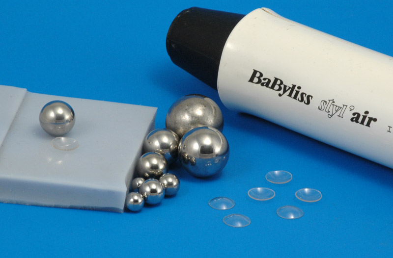
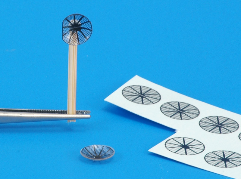
What I ended up doing is cutting (scribing) clear discs using a circle template, heating them one by one with an old broken hair curler to around 100°C (by restricting the inlet air flow), then forming them with an 11 mm bearing ball on a soft rubber block. And voila: sweet transparent parabolic shapes, similar to eye lenses, measuring 8 x 1.7 mm.
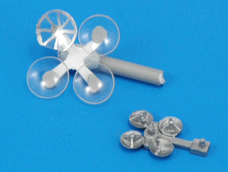
Here's a very rough prototype of the replacement antenna, also to show the size difference. It's actually more a concept than a prototype. I used a Molotow pen to see how the spokes would look. I planned to use a metallic silver Alps decal for this.
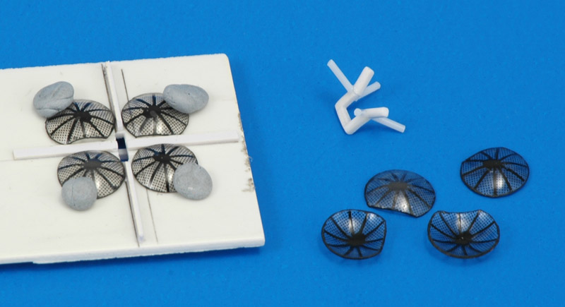
The second prototype looked a lot better. I printed decals on my Alps and made a radial cut next to each spoke. That allowed to decal to conform to the interior of the heat-formed lens without any problem. My decals were a bit too large, and I cut off the excess decal film, losing the edge detail of the decal. By painting the edge of the lens in the same color as the decal I still had a nice edge to the mesh of the antenna. Time for series production, ten pieces total for me and another member of the club team (four and a spare each).

Note to myself here: when printed as CMYK, the grey 'pie pieces' are done in four inks. My 'accidental' method was to define the artwork in black and grey, then try to print it in spot color Metallic Silver. The printer in its wisdom did not use Metallic Silver, probably because of the grey parts in the CorelDraw artwork, and used pure black instead. This gives the result shown in the photo. And it was a lucky strike, because the real antennas were much more black than silver.
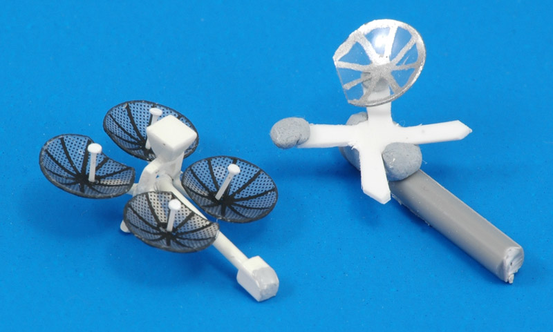
The next challenge was to build the rest of the antenna structure. I built a little jig, in which the antennas were spaced 1.5 mm between the cut-off sides of the parabola antennas, and 0.4 mm between the rounded sides. From various photo measurements I cobbled up the approximate dimensions of the strange frame that holds all four antennas, and started with a 'beaker' shaped U-frame built from four 3x1x1 mm pieces and one 2x1x1 mm piece. This was positioned at the right depth inside my little jig, for which I cut a hole in the middle, so the frame could project 2 mm in front of the parabolic antennas. With this in place, I attached four 0.7 mm rods, connecting each antenna with the 'kink' in the previously built frame. The result is very vulnerable!
Before assembly, I overpainted the four parabolic dishes with Alclad ALC-313 'Klear Kote Matte' on both sides, to take away the gloss and achieve the look I saw in photos. But the effect hardly shows in this photo. The send antenna was built from a piece of 3 x 3 mm plastic card and a piece of 2 x 2 mm plastic rod, filling the rest with Apoxie. Epoxy glue was used to bond the four parabolic antennas to the frame.

The 'mast' was a 10 x 1 mm plastic rod, glued into a 3 x 2 x 2 mm plastic block. Two 1 x 1 mm magnets were also installed in the block, and everything was painted MRP-99 'US Navy White". The last thing I added were the antenna receiver stems in the parabolic antennas, made from white stretched sprue with 1 mm Waldron-punched discs at the ends. They were glued on off-center, and tilted, like the real ones. The difference between the first concept and the end result made me happy :-)


CSM plus LM combination

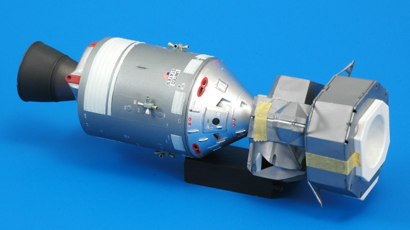
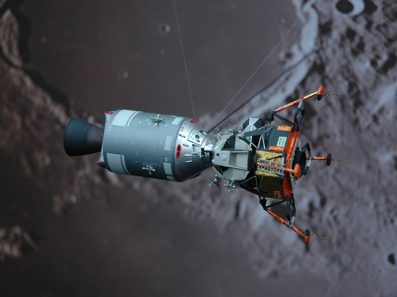
A preliminary view of the CSM mated to the LM, which is the flight phase that my contribution to the club build represents. The CSM and LM connect with magnets.

More photos to follow.


Our Apollo 11 display at Euro Scale Modeling 2019

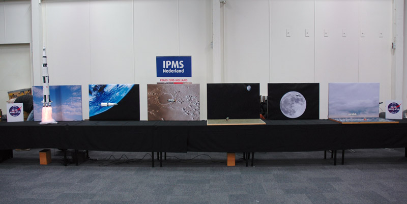
First an overview of the 'Regio Zuid-Holland' stand, before the Euro Scale Modeling 2019 show opened. It shows the six stages of the moon flight that we depicted with models. All models are in 1/96 scale, each with a background panel. It was a bit of a gamble whether we could fill a eight meter stand with just seven models, but I think it worked!
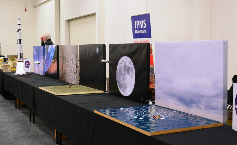
Left-side view of the stand, starting with the imposing Revell 1/96 Saturn V on a lighted column of smoke. (Photo by Jan de Wit)
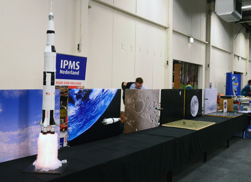
Right-side view of the stand, which was the first view of most visitors, because of the traffic patterns in the halls. This was a bit unfortunate, since they walked against the timeline. I can only hope they realised what we tried to show. (Photo by Jan de Wit)
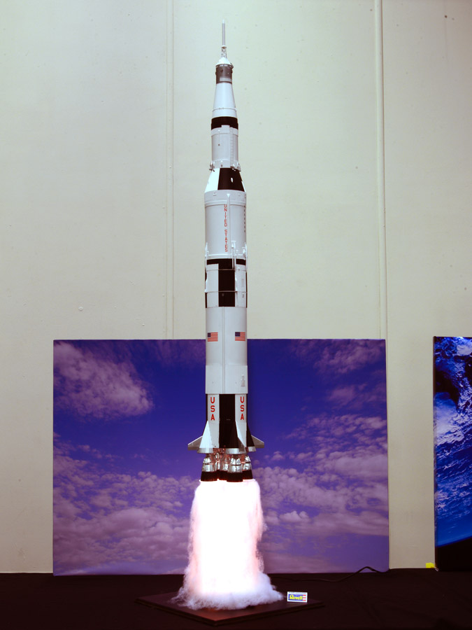
The Revell 1/96 Saturn V was built by Jan de Wit. Of course the it was way taller than the background panel, but that emphasized the massive size of the rocket. This model was kindly sponsored by the Revell importer of the Netherlands.
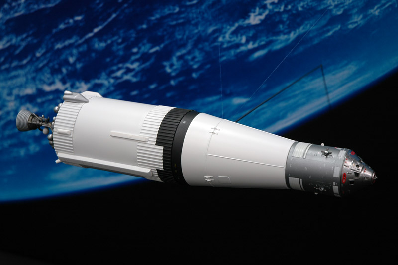
Nick van der Windt built the third stage with CSM, during translunar injection. The model is a combination of the Revell Saturn V's third stage plus a RealSpace CSM.
Here's my finished model orbiting the moon, just before undocking of the LM, that has already unfolded its landing gear. Like the model shown above, it photographed nicely against the background. Unfortunately the sweet parabolic antennas were hidden by this view.
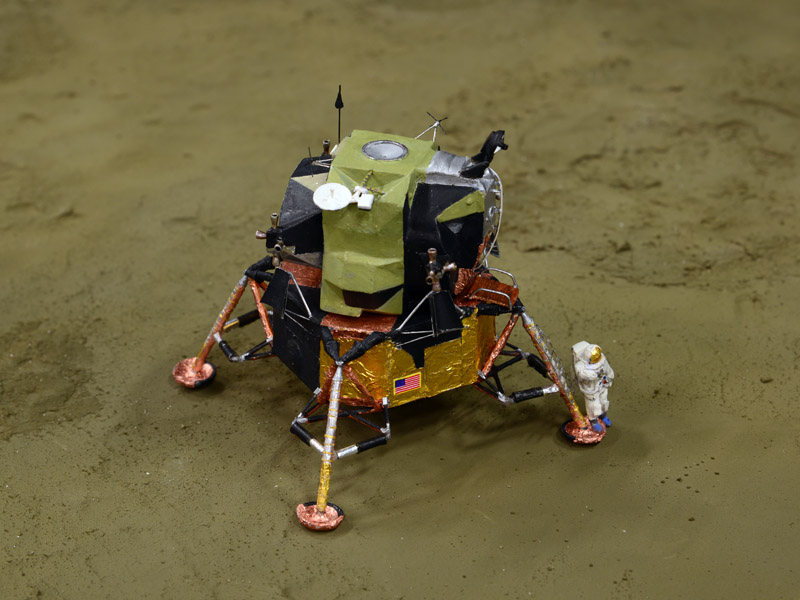
Hans van Gelder built the model for the fourth stage, using Revell's trusty old 1/96 Lunar Module, with a lot of modifications. As you can see he recreated the moment Neil Armstrong stepped on the moon.
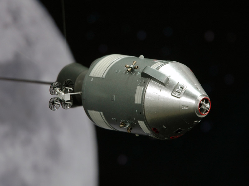
Reinhold Bogaard built another RealSpace CSM to depict the return flight from the moon. He used the other set of parabolic antennas shown in the build report above.
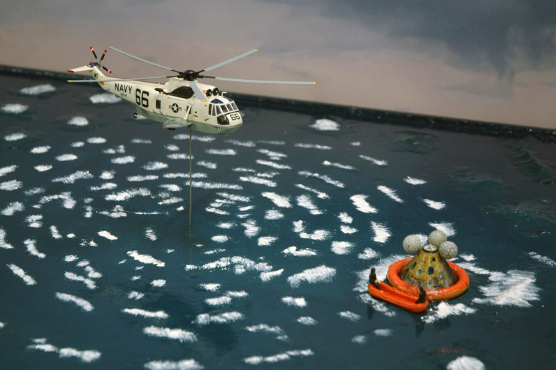
Chris van Ravesteijn used a Tamiya 1/100 Sea King to depict the sea recovery of the Apollo 11 crew. I redrew the yellowed decals and had them printed by Spotmodel.
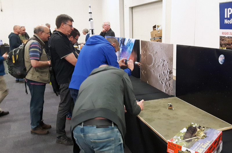
Our six-man team really enjoyed this sight that went on all day long: lots of visitors taking photos of the models. It made up for all the hard and sometimes frustrating work. And at the end of the long day we received the prize for 'Best group display'! (Photo by Reinhold Bogaard)


Links


Return to models page