| Here's a brief look at my modeling desk, with some practical aspects shown as well. |
Mid 2001, I drew up a requirements list for an ideal modeling workplace, as a design exercise, just for fun. For example, my old workplace had open closets, so you could see most model boxes. I would rather prefer to have everything in drawers and closets, creating a much cleaner appearance. And I would like a much much larger working space, meters wide if possible. I translated these requirements into a design, and through several iterations I ended up with something I really liked. It was so much better than my old work place, that I starting thinking about actually building it. I decided on two drawer blocks, with a very long (2.5 meter) desk on top. Hanging from the wall I wanted two closed closets for kit box storage, and in the center one wide closet with transparent doors to display my finished models (all eight of them). On the left side I planned a small TV on a swing support, and to make it symmetrical, I wanted a spray booth on a swing support on the right side. I could 'park' my spray booth on the side, and pull it towards the center of the desk when I needed it.
It took me a long time before I found the components I needed. At first I looked at office furniture, but I could not find what I wanted. In the end it turned out that Ikea kitchen components were almost ideally suited. By repainting them, and by adding a different desk piece, a kitchen look could be avoided largely. From the Ikea kitchen catalog, I selected the standard Faktum components with white MDF Applad doors and drawer front pieces. With the selected components, I could finalize the design. The drawing shows the design, with my old work place drawn in dashed lines.

I modified the Ikea components slightly. I added an MDF plinth instead of standard Ikea plinth, to bring the desk height down from kitchen sink level to normal desk level. I replaced the frosted windows in the Applad doors with clear glass windows. The main components were repainted in a brownish dark gray, and the front parts in some sort of terra cotta red. The painting was a major drag, because I wanted a matt finish. The alkyd paints I used were only available as satin paints, in practice a glossy satin, and I did not like the results at all. Matt clear finishes were difficult to find, but I found an acrylic matt varnish at last. It is quite vulnerable though.
I wanted a glass-covered desk, because of its appearance, and because I expected it to be easily cleanable. I used a 30 mm MDF plank as the basis, with Meranti strips all around, protruding 6 millimeters. After painting, the sheet glass was laid in the 6 mm cavity. The appearance was as expected (love it!), and indeed it is easily cleanable, but it also gets incredibly dirty. Every speck of dirt is visible on the high-gloss surface! Another drawback is that the lighting cannot be mounted under the top closets, because their reflection in the glass surface would blind you. I am working on a lighting set-up to solve that, and it appears it could be quite pretty too.
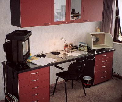
I mounted three-socket electric outlets left and right under the desk, which turned out to be very convenient in every day use. Possibly I will add mountings for floodlights under the desk, to allow for model photography. But I don't have concrete plans for this yet.
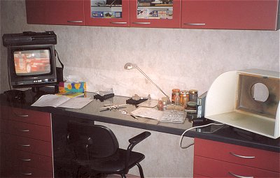
Overall, I am really happy how it turned out. I can only think of some minor problems. One problem is that the desk is possibly too large: I can't reach the drawers completely from my chair! I guess I have to update to an office roller chair, but I am not very fond of chairs on wheels. The width/depth ratio of the desk seems optically incorrect. An extra 10 or 20 centimeters extra depth would have been nicer, but that would be incompatible with the Ikea kitchen components. These minor points do not spoil my satisfaction! Total cost was around 700 euros. I did not count man-hours spent on (mainly) painting.
The last item I finished was the spray booth. After finishing the basic modeling desk, I made cardboard mock-ups to design a booth that would fit the overall picture. I had a blower from a kitchen furnace (as used in my old spray booth), and I wanted a storage area for the flexible hose. The booth consists of three main parts: a rectangular air box in which the blower is located, a small storage box for the exhaust hose on the right side, and a working desk with curved walls to the front. Because my design had a fairly complex shape, I made a simple CAD drawing. The box for the blower turned out a little smaller than I hoped for, possibly reducing its performance a little, but I really did not want to build a bigger booth.

I built the booth from 10 mm MDF, and one hefty 30 mm piece of MDF where it connects to a TV wall mount. I used epoxy glue throughout, because the design was not very good from a strength point of view. I needed some putty to make all the connections nice and smooth, but it looked really good in the end. In the photos below it is in primer paint, still missing a filter, and with the back panel (on which the blower is mounted) removed. The spray paint reveals that I used it many times while under construction :-)
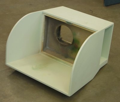
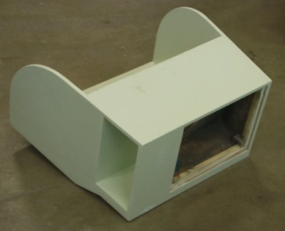
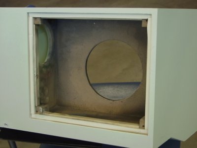
After 22 years of use, I finally made some photos of the finished product. The booth has gained a good patina of all kinds of paints. A new filter is fitted, which explains why it looks so clean. On the right you can see the flexible air hose exiting; on the left you can see it running upwards towards the exhaust above the window. The booth has four rubber feet, so I can move it around easily.


The detail photo shows the radial fan. I often read that a spark-free motor is required to avoid igniting combustible vapors, but I don't know whether my motor is spark-free. And I want to add that I'm not so sure that these warnings are valid: firstly the fuel:air ratio needs to be within a defined limited range to ignite, and I doubt whether we achieve that; secondly I have never ever read of a modeler's spray booth catching fire.

This rear view shows the compartment to store the flexible exhaust duct (a bit worn after 30 years), held with a velcro strap. On the back side you can see the removable panel on which the blower is mounted. The step in the bottom is a heritage of the time when the spray booth was mounted on a TV wall mount, so I could swing it to the optimal position. The spray booth is now mounted on rubber feet.

I have plans to build a new, more powerful spray booth. When I'm blasting away with (for example) the Paasche H cranked open, the spray booth cannot keep up. Also, the flow pattern at the filter face is awkward, in some areas the flow appears to be reversed. This is most likely due to vortices, that are caused by the bad aerodynamic layout of the radial fan sucking through a hole in a flate plate. My ex-kitchen hood blower is around 55 Watts power, but I have a 150 Watt blower waiting to be converted into a paint booth. It will also have a better aerodynamic shape.
This section was moved to a separate page: Spray booths. It's mostly about the selection of a proper blower / fan. The analysis is quite involved, and probably too much for the average modeller, but I wanted to know the answer
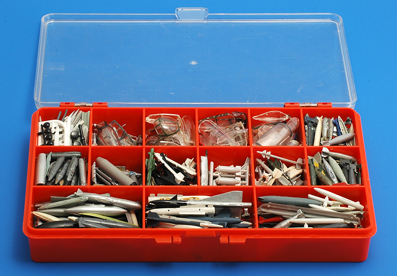
Often mentioned, hardly ever shown: the famous spares box. Well, here are mine! Hundreds of wheels, dozens and dozens of rockets, bombs and tanks, pilot figures, engines, canopies, landing gears. The majority of these items come from a the disposed model collection of a fellow modeler (hi Berry!), with my own surplus stuff added.

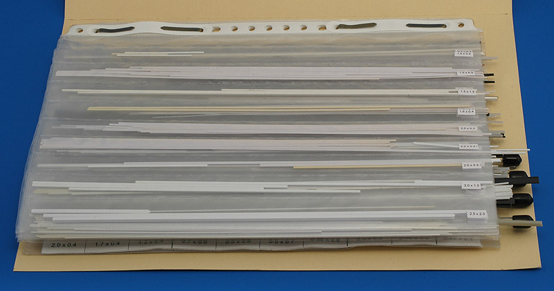
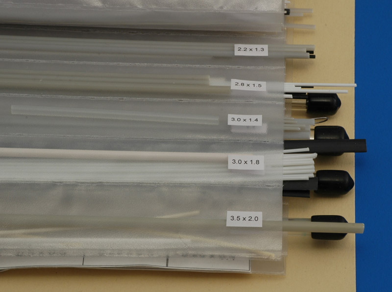
My collection of Evergreen, Slaters and Plastruct bags with strip and rod drove me nuts. I could never find the size I was looking for. I recently solved that problem. I used plastic sleeves to put documents in a folder. I used a temperature-controled soldering iron set at 225C to make (say) ten vertical pockets in each sleeve. I made around ten sleeves, and put them together in a paper folder. And then I filled nearly all 100 pockets with all my strip and rod and profiles and metal wire and Albion tubing. I even made small stickers with the dimensions of the content of each pocket. All in all it was a couple of hours work. But it works really well. Every time that I used it ever since made me very happy.

