Dragon (DML) 1/72 YF-22A
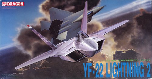
I considered the YF-22 an extremely ugly aircraft when it was presented to the public. And when it won the ATF contest over the beautiful YF-23, I liked it even less. Nevertheless, the aircraft interested me on a technical level, and I couldn't resist when I saw the Dragon model. And after some years, the shape doesn't look that bad anymore, perhaps because of even uglier stealth aircraft that followed it.
I stopped construction of this model when I discovered the undersize canopy. That really spoils the 'face' of a model for me. Once you know the problem, the nose looks somewhat like a chopped car or a cartoon of a figure with a far too small head. Initially I thought the problem could be solved by reshaping the canopy, making a vacform mould and vacforming a new canopy. But more work is required: the top half of the front fuselage must be modified too, otherwise the upper front fuselage will have four instead of two facets. Until I dare to start that involved process, this model will be on hold.
|
Model quality
When I wrote this review, I already owned this Dragon model for ten years. It has defined the shape of an YF-22 for me, and I find it rather difficult to judge its shape objectively. Together with a friend I did a comparison of the companion Dragon YF-23 and Italeri YF-23, and the Dragon model's shape was by far the least accurate of the two. This worried me about the Dragon YF-22, but so far I haven't found major errors. It seems that the biggest problem is that the wings are pinched some 2 mm deep at the root, which looks very strange, but is near impossible to change. Also, the pitot tube is far too small compared to the massive boom on the real aircraft. The overall dimensions (span and length) are pretty accurate compared to USAF Museum data. Further observations about the shape to follow later.
The model has almost no panel lines on the upper side apart from the control surfaces, and that makes the model look a bit toy-like. On the lower side the engine bay doors are present, plus of course the weapon bay doors, and on the sides have some access panels. Some vents are missing however. The Aerofax YF-22 book contains a drawing showing some panel lines, plus a few detail photos that show them for real, confirming that the drawing is correct. The YF-22 that is (being) reassembled for display at the Edwards museum is reported to show some panel lines, specifically around the engine bay doors on the lower fuselage and some side bay panels, but most of the upper panels are sealed.
The fit of the model is not very good. The lower wing fits too deep in the upper wing and requires packing. The fit of the vertical tails is non-existent. The inlets require lots of filler too. The horizontal tail mounting is extremely weak and basically unusable. And then the sink marks! The models suffers really badly from them, most notably the wings, the vertical tails and the inlets. Another problem is the peculiar texture of the whole exterior. Possibly it is supposed to simulate composite materials? I sanded it off completely, a major job. The canopy is quite good though, nice and clear, and fits well. Its only problem is a weld line due to two injection ports of the part. It's possible that the canopy is too small compared to the fuselage, the canopy of the real thing is very large. I cannot judge it before painting is finished, the clear canopy frame distorts the impression. The cockpit interior has nice detailing (mostly fictitious though), but its position inside the fuselage is plain silly. The landing gear legs are very nicely detailed, but reportedly too weak to carry the model. There are no openable weapons bays.
This Japanese site shows the finished Dragon model.
Aircraft Resource Center has several walkarounds of the YF-22 that was on display at the USAF Museum: 1, 2 and 3.
Other YF-22 models
Four other 1/72 YF-22 models exist, with thanks to '172flogger' from ARC:
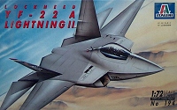
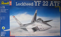
Italeri (194), build reports by Meindert de Vreeze, Carmel Attard on Modeling Madness, 'djos' on BritModeller and 'dragan_mig31' on BritModeller. It was reissued by Revell Germany (4314), Testors (656) and Tamiya (60714, Warbird 14). The model was badly copied by Lee and Kitech/Zhengdefu. The Italeri model has a rather deeper spine (which is incorrect I think), and two 'folds' running parallel to the spine (much too deep I think), no pinched chord at the wing root (correct), more small air outlets (correct), much deeper control surface panel lines, a few extra 'normal' panel lines that are raised, a strange canopy, and the large 'YF-22' markings on the tail are not slanted.
| 
| 
| 
|
| Italeri 194
| Revell Germany 4314
| Testors 656
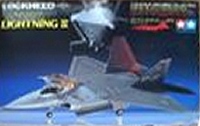
| Tamiya 60714
|
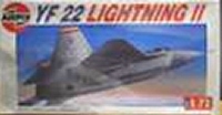
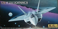
Airfix (05027), review here. Also issued by Heller (80432)
| 
|
| Airfix 05027
| Heller 80432
|
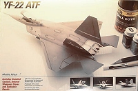
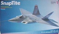
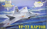
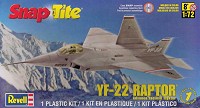
The Monogram model started as a SnapTite desk model of 15 parts without landing gear or weapon bays (1154, described here), reissued by Revell USA (85-1186, Thunder Squadron), and again in 2012 (85-1198). A reworked version with landing gear and weapon bays and issued by Revell USA (04461, review here).
| 
| 
| 
|
| Monogram 1154
| Revell USA 85-1186
| Revell USA 85-1198
| Revell USA 04461
|
John Burns PAK-20 lists a 1/72 'ATF F-22' by Lunar Models, probably made of resin, but I haven't found any details of this model.
If I were to build another YF-22, it would be a difficult choice. The pinched wing roots are the most annoying aspect of the Dragon model. The canopy and basic cockpit detailing are pretty good though. Italeri has better wings, but the creases parallel to the spine that look a bit strange, and very deep control surface engravings.
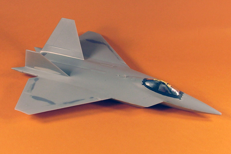
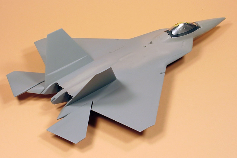
Construction
| This report starts with the model progressed to the state as visible on the right. Dragon's model is fairly simple, with very few parts. If I remember correctly, I only installed the cockpit and main landing gear bays before gluing the fuselage+wing halves together. The cockpit construction was very weird, and I modified it considerably. Instead of gluing it to the lower fuselage half in a very reclined position, I glued it to the upper fuselage part in a more normal attitude. Back then no cockpit photos were available, so I engineered it myself. I added two braces to the rear of the ejection seat, and painstackingly scratch-built the large HUD on the coaming. Then I closed the cockpit by gluing the canopy on.
| 
|
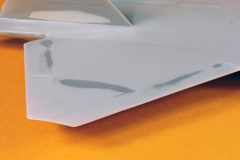
| A big problem of the model are sink marks. The wings are rather thick mouldings, with predictable consequences. I further complicated matters by using a soft putty (Tamiya's), which sands too easily, so you keep sanding away too much. Sanding is another keyword for this model, since it has a strange texture all over its exterior. Lots of sanding later, the model was smooth.
|
| Many more sink marks on the lower side of the wings. This view also offers a peek in the main landing gear bays, which look way too voluminous and square to me. I had spray painted them white before I installed them.
| 
|
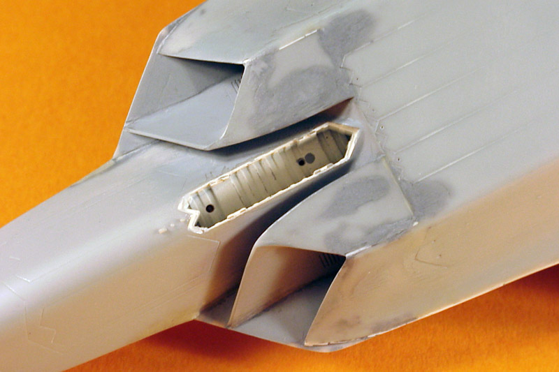
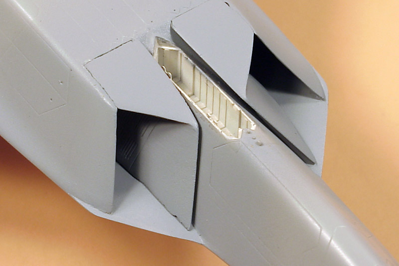
| Did I mention sink marks already? The intakes suffered as bad as the wings, and the fit of the intake parts was also really bad, about as bad as the vertical fins shown below. The intakes of the Dragon model are too narrow compared to the real thing. The problem lies in the diverter gap that is much too wide at the front, which is clearly visible here. Further down you can see the changes that I made later.
|
| This photo again shows the intake boundary layer diverter gap problem, that I corrected later. The pitot tube hole is not standard by the way, I enlarged it greatly to accept a metal pitot boom that I'm building. Dragon did not include the large test boom used on both prototypes.
| 
|
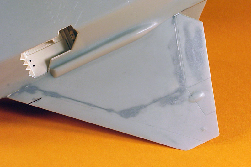
| The fit of the vertical tails is non-existent. Lots of Milliput later it looked better. But unfortunately it now shows an error: at the rear end, the vertical tail should connect with the fuselage outboard of the slot, and not inboard as on my model. See also the next photo. The vertical tails should be placed about a millimeter further outboard to solve this problem. Another problem: the outboard surface suffers from yet another major sink mark (see first photo), and I had to rescribe a part of the rudder.
|
| Another problem area is the tail section. I don't recall exactly what it looked like initially, but again lots of putty is needed to create smooth surfaces. With hindsight I should have used a two-component putty like Milliput to build up this area, not a solvent putty like Tamiya's.
| 
|
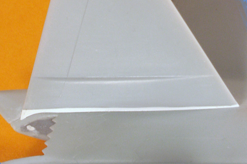
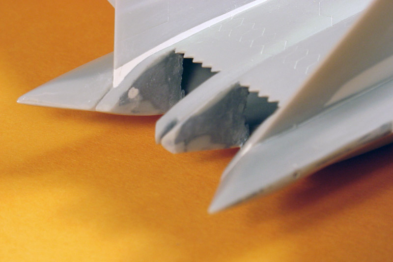
| The serrated edges of the movable parts of the nozzle don't fit nicely. And because of the natural metal finish, some special techniques must be used in making them fit properly. I also thinned the moving nozzle parts considerably, but I have to check again whether that was the right thing to do. I believe the nozzles can be fitted in only one position, since the whole bare-metal area appears to flex/bend with nozzle movement. Having a kink at the 'hinge' wouldn't be correct.
|
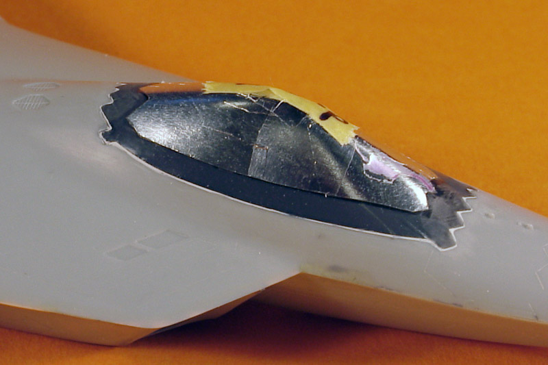
| The Dragon canopy is also quite nice and clear, but it has some weld lines (not too bad though). I fitted it to the fuselage without trouble, and filled the narrow gap around the canopy with Milliput. Only then I noted that the panel line formed by the canopy attachment is wrong. It is one long gentle curve, but it should be two straight lines, which makes sense for then-current stealth technology. Correcting it now will be difficult: the clear plastic is very hard while the gray plastic is much softer, and therefore rescribing will be more than annoying. I thought I was close to painting the model, therefore the canopy is already covered with Cheap Chocolate Foil
| 
|
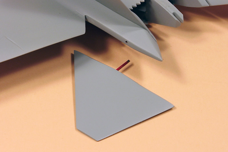
| The way Dragon engineered the mounting of the horizontal tail planes leaves a lot to be desired, and I changed it. First I drilled a 1 mm hole right through the tailbooms, and glued a piece of plastic tubing in the holes. Corresponding (but smaller) holes were drilled in the tail planes, and steel wire was glued in the holes using CA. I painted the steel wire with (red) paint to make the fit in the tube tighter. The tail planes can now be rotated and posed.
|
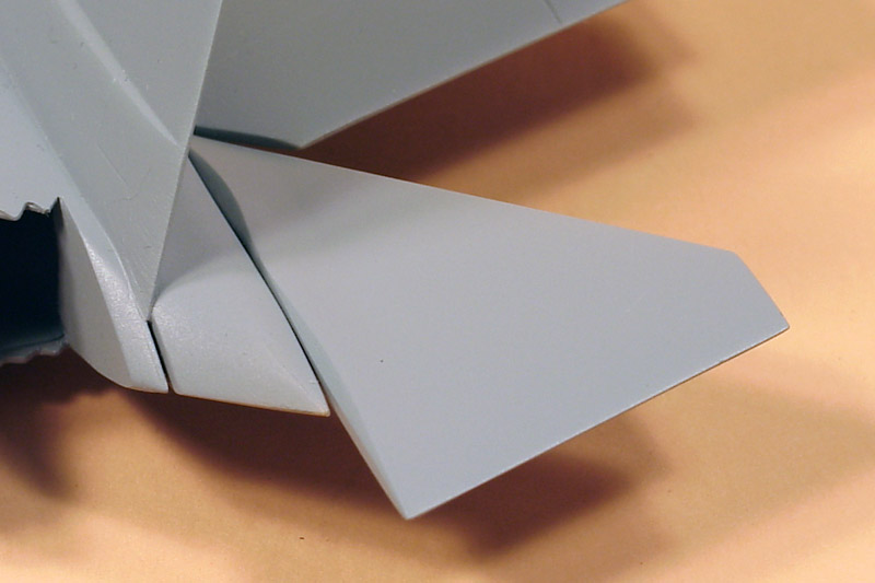
| Another modification: the inboard sides of the tail planes were modified with 'cat's eyes', chamfered edges of the edges of the control surfaces, to avoid 90 degree corner reflectors when the surfaces are moved.
| 
|
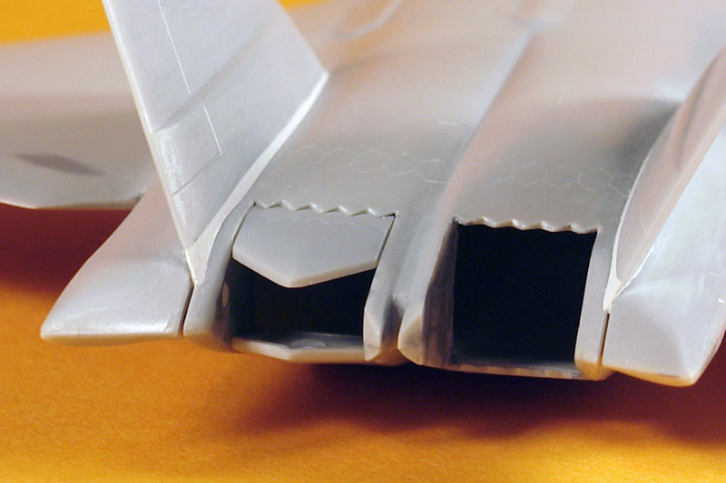
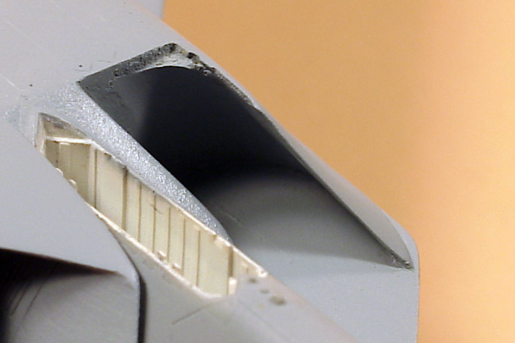
| Here are the intakes after modification of the diverter gap (but not glued back to the model). I could pop the parts loose easily, and modified the inner wall considerably. Unfortuantely the paint already covers the modifications. The diverter gap is now only 1 mm wide. The correction is not perfect though: the inboard intake wall now has a considerable wedge shape (it becomes thicker towards the rear), and photos of the real aircraft don't show that. It was the best I could do without major modifications.
|
The intake ducts are only some 20 mm deep, and end with a solid bulkhead, that is quite visible when you look into the intakes. I saw two options to make the intake ducts to look longer. Initially I considered actually lengthening the ducts with a home-made vacform piece. Making these pieces would be a lot of work though, and I would have to cut openings in the rather thick fuselage parts; not an easy job with a completely assembled model.
The second plan was more subtle but also more of a compromise. The ducts on the real thing curve rather strongly, to clear the weapon bays. I figured that I could use this curvature to hide the short duct length. The end of the inboard intake piece was rounded, and in the rear outboard corner of the intake I created a 6 mm radius with Milliput, using a piece of tube. This creates the impression of a strongly curved intake. Under some angles you can see the trick, but overall I think the effect is pretty good.
| 
|
| And this is how the model looks like after a partial base-coating with Humbrol 127. After all these years I'm slowly starting to like its shape :-)
|
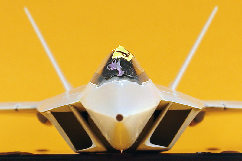
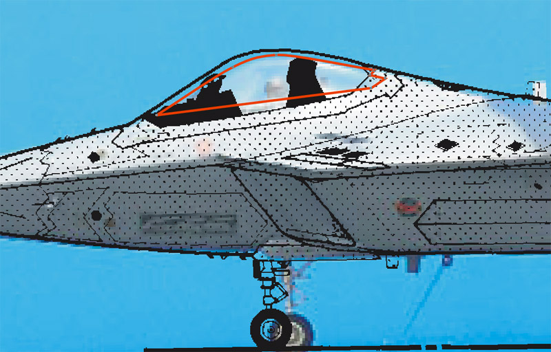
For a long time I had the suspicion that the canopy was considerably undersize. In 2009 I overlayed a photo of a built-up model with the line drawing from the Aerofax booklet. I outlined the kit's canopy (from the background photo) in red. And indeed it showed that the canopy should be around 1/3 taller. I had also overlayed photos of the real thing with the same drawing, and they matched well, so I consider the drawing accurate. Another clue are the angles visible in a front view photo published by Lockheed. I measured around 55 degrees for the lower front fuselage facets, and 60-61 degrees for the upper front fuselage facets. On the model the later is around 54 degrees. The difference doesn't sound too impressive, but it results in a much lower canopy.
A quick check of the Italeri model showed that it had roughly the same angles, but the canopy is less rounded at the top, giving a slightly higher canopy. But it's still considerably undersize I believe. That leaves the Airfix and Monogram kits, but I don't have access to these to check their cockpit / canopy shape. An easy but partial solution for the canopy problem is to pose it open, like on this Lockheed YF-22 ATF von Günter Bobinger. But I had glued on my canopy solidly, so it wasn't an option for my model.
| 
|
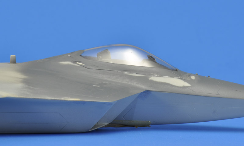
| I painted the canopy area in dark gray, to give the canopy frame that color on the inside. Some sanding followed to make the caopy frame nice and flush with the surrounding area. But since I stopped this build project at this point, I removed the Cheap Chocolate Foil prematurely.
|
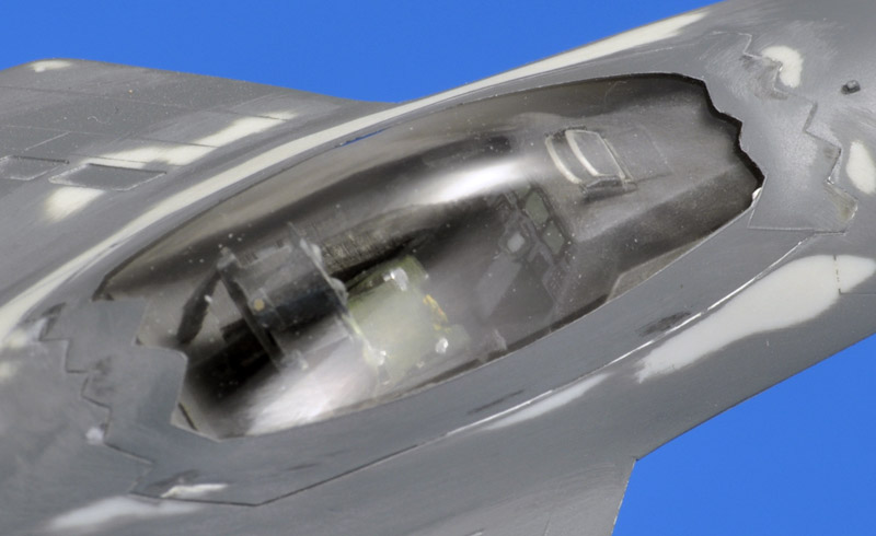
| A peek inside the cockpit of the model, hindered by the glare. It has an ACES II seat with green cushions, and an instrument panel with green digital screens. State of the art modeling in 1995 :-)
| 
|
Colors
I studied the colors for a very long time, and this is what I concluded. Three colors were used on the YF-22, most likely those used on the F-16 (FS 36375, 36270, 36118), in an almost identical scheme. The complete nose and underside are painted in the lightest color. The middle grey color is used on the outboard vertical tails, and the remainder is painted in the darkest grey color. Many models have the outboard verticals painted in the darkest grey, but it really is a different color (you can see the overspray of the darkest grey on the root). On the F-16, the upper and lower sides of the nose are (were) painted in two different greys, but after looking at every available YF-22 photo I believe one color was used on the YF-22.
Decals
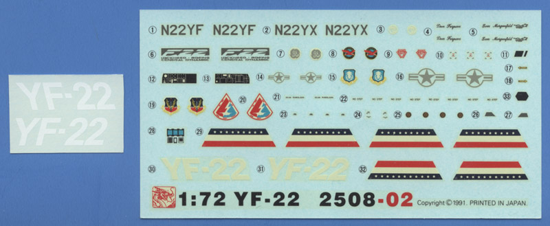
The Dragon decal sheet is quite funny. It contains incredible spelling errors: how about "LQCKHEED-BQEING CENERAL DYNAMIGC" in decal 6 ?!? I always thought it must have been designed by a Hong-Kong or Chinese citizen that spoke no English at all. But another possibility is that this was done for copyright reasons.
The large slanted 'YF-22' script on the tail is also problematic: the decals are too small (some 10 percent), not slanted enough, and reportedly not opaque (FSM review February 1992). Therefore I also bought an Italeri kit as a decal donor. But Italeri's 'YF-22' logos are not slanted at all, and 15% too large.
I started making vector graphics artwork for subsequent Alps printing. I measured the required size of the 'YF-22' logo, used Arial Bold font, modified the '2', placed the dash a little higher, and finally slanted the logo some 14 degrees left and right. I also made the test markings around the APU exhaust, measured from photos. The Alps-printed decals are of more than excellent quality.
| 
|
Return to models page