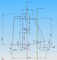

The pages showing Stephen Endersby's Me 163B CAD models have generated quite abit of interest from traditional as well as other CAD modellers. In order to help others create there own versions this page gives details of the dimensions used by Stephen to create his model.
The dimensions presented on this page are either scaled from original Messerschmitt Me 163B drawings, or created to give the model the 'correct' look. Any help in firming up any dimension would be greatly appreciated. The images shown in this page are from the sketches used to create the model, not from any engineering drawing. As Stephen has no intention other than to create a virtual aircraft, engineering drawings are not necessary. This page is very much a work in progress and will be updated as more information becomes available. Where appropriate the German terminology is used with an English translation.
| Length (m) | 5.92 | |
| Height (m) | 2.76 | |
| Wingspan (m) | 9.3 | |
| Wing Area (sq m) | 18.5 | |
| Wing Sweep (Deg) | 23.3 | at 1/4 chord |
| Wing Aspect Ratio | 5.7 | |
| Wing Root Profile | Gott 765 | |
| Wing Tip Profile | NACA 0008-1,1 20 | |
| Wing Geom Washout (Deg) | -7.033 | |
| Wing Root Incidence | 3.33 | |
| Wing Tip Incidence | -3.7 | |
The main fuselage section is circular in section, defined at eleven 'Spanten' (frames) as well as the nose (RVK, probably short for 'Rumpf Vorderkante') and tail (RHK, probably short for 'Rumpf Hinterkante), the electrical generator spinner is seen as separate item. The diameters used are listed below. All the spant locations are taken from Messerschmitt drawings; note the fixed 450 mm pitch. The diameter at Spant 8 is known, all other diameters are approximate.
| Item | Location (mm) | Diameter (mm) |
| RVK | -80 | 145 |
| Spant 1 | 450 | 785 |
| Spant 2 | 900 | 1025 |
| Spant 3 | 1350 | 1146 |
| Spant 4 (Datum) | 1800 | 1200 |
| Spant 5 | 2250 | 1201 |
| Spant 6 | 2700 | 1158 |
| Spant 7 | 3150 | 1078 |
| Spant 8 | 3600 | 956.4 |
| Spant 9 | 4050 | 828.5 |
| Spant 10 | 4500 | 674.5 |
| Spant 11 | 4950 | 509 |
| RHK | 5700 | 237 |
The canopy and upper fairing side profile is given in the drawing below. The attachment of the fairing to the main fuselage is also given. All dimensions in bold are taken from a Messerschmitt drawing.


Reasonably clear drawings of the canopy sill and cross section have been scaled to provide the information to construct the canopy.
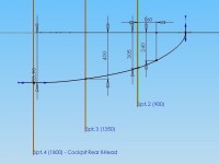
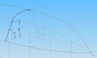
The keel line and lower fairings are the least defined areas of the CAD model in terms known aircraft dimensions. The images below show the dimensions used to create the correct look.
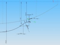

The basic wing planform is known from Messerchmitt drawings, which show the early shorter Trimmklappe (trim flap).
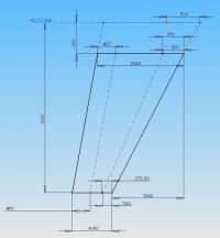
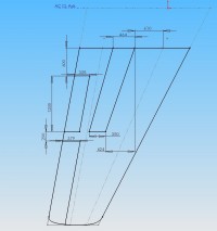
The basic wing plan form did not detail the wing tip, this was scaled from another drawing.

As with the the wing, the basic fin planform is known from Messerschmitt drawings. But as with the wing, the fin tip had to been scaled from a separate drawing.
