Me 163 kits and accessories
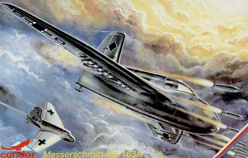

This page consists of two parts: an in-the-box review by Ruediger Landmann, and a construction/conversion report by Rob de Bie, which reveals a number of serious outline flaws. See also the reports by Julian Herrero and Christian Meyerhoff on the Condor kit.
The following description of the Condor 1/72 Me 163A kit is largely supplied by Ruediger Landmann, who is building three of these kits. The box contains of a single sprue, a tiny injected canopy, a small fret of photo-etched parts, a clear decal film for the instrument panel and a decal sheet.
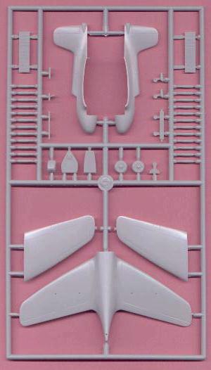
| The injected parts are cleanly moulded with very little flash. They look nicer than the average MPM kit (although Condor is part of MPM), being smoother and with no chunks missing from the mould. Later I found out why: Condor kits are produced in conventional 'long-run' metal moulds, whereas MPM kits are produced in non-metallic 'short-run' moulds. Overall, the outline seems quite good, but the wing leading edge is more of a continuous curve than kinked-but-otherwise-straight. Perhaps the more continuous leading edge represents the mysterious 'V4' wing? They have leading edge slots molded on, which appears to be correct for all Me 163A's except the first prototype (KE+SW). But the flaps are missing, and as far as is known only the first prototype lacked them initially. Trailing edges on the wings and tail fin are quite thick. The canopy is very small and rather thick, and this makes it a waste of time to spend time on the cockpit detail, unless you're going to build it with the canopy open. The cockpit is quite reasonably represented. There are a few fit problems. The point where the one part fuselage underside/lower wings meets the upper fuselage assembly just forward of the wings' leading edges leaves a *very* large step that needs a lot of sanding to remove. On each of my three attempts, I have been unable to get the cockpit interior assembly to fit inside the fuselage. Perhaps I've been doing something wrong, but the only way I could eventually close the fuselage has been by doing some pretty extensive trimming of the interior parts - the rear bulkhead in particular. Other than the two points above, fit is excellent - with the way that the upper wings meet the fuselage sides being especially pleasing. The rocket exhaust is *far* too large and would require some fairly major surgery to correct. Also, the R4M rockets are grossly out of scale, being far too large and not very well proportioned. I am going to adapt the R4M rockets and racks that came with a Hasegawa Me 262A instead. |
The photo-etch fret contains parts for the cockpit, the start dolly and the wing tip skids. The start dolly is the improved suspension-type gear, not the stiff unsprung gear fitted to KE+SW initially. Photoetch really wasn't a good choice for the wing-tip bumpers which really need a more 3-dimensional approach. I'm building them up with Milliput, using the PE parts glued in place as guides. | 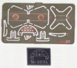
|
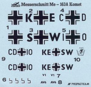
| The decal sheet is printed by Propagteam, which means very thin but vulnerable decals. It offers two options, KE+SW and CD+IO. The 'K' in KE+SW looks wrong, and 'V1' was most likely never applied. See also the comments on the 1/48 Flashback Me 163A |
The back of the box shows drawings of the cockpit, Me 163B seat (!), extended skid, starting dolly (sprung version) and the tail skid. Some of the detail views are a little questionable. The colours of the interior are conjectural at best and this painting of the cockpit differs in places from the only interior photo of the Anton that I know of. Likewise, the painting of the tail skid differs from the only close-up photo that I know.
The painting instructions are shown below. They look a little better in the real instructions. Color key: A = RLM02, B = RLM76 (deduced from color matches). I'm still not convinced that KE+SW was painted in RLM02 though, but many people think so. A photograph of the rocket-armed Me 163A shows sharp rectangular spots instead of mottles.


I bought this kit some time ago, and did not touch it for a while. Then I recently saw some pictures of the built-up model, and frankly, they scared me! The model looked only remotely like a Me 163A: the fuselage was extremely fat, the canopy looked very weird, the tail looked stubby, and its attitude on the dolly was most unnatural. A friend who wishes to remain anonymous provided his model for the following photographs. It was built straight from the box, except for a Falcon canopy.
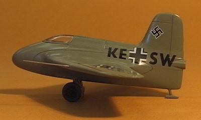
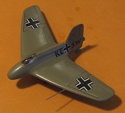
I decided that a conversion would be interesting, so I went ahead. After consulting the Me 163A drawings available to me I decided not to use them. They looked equally weird, and knowing the lack of information on the Me 163A, they could not have know a lot more than I do. I decided to work from photographs only, and do an 'optical' reconstruction. This would only make the project a more interesting experiment. It does however disregard the possible problem of incorrect overall dimensions of the kit. The whole conversion job was not planned ahead in any way. I would find a problem, do some measurements on pictures, and decide on a way to deal with it. After gluing the top fuselage halves together, the 'ad-hoc' conversion went something like this:
I started with the canopy. It looked very small, and the slope on the front end was way too flat. I deepened the cockpit opening 1 millimeter at the rear, and added card to the canopy to make it higher too. Next I glued a strip on the centerline, to get the contour right by sanding. The rest was filled with Milliput. It still didn't look right though
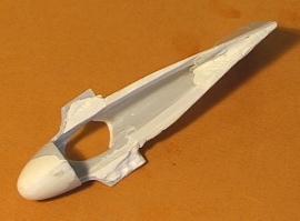
Next were the wing roots. They looked horribly un-aerodynamic at the rear. I chose a drastic solution: I cut away the rear 50% of the complete root by sawing along the inner and outer panel line. It would be restored later with Milliput
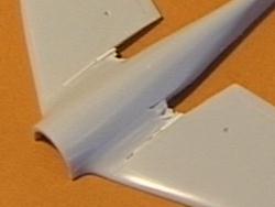
The wing root removal made reconstruction of the fuselage necessary. I cut pieces of card to the inside of the top fuselage, and Milliput on top of that. The rocket exhaust, being way too large, was also cut off
Another weak point is the shape of the nose. Its apex sits too high, which completely destroys the appearance. I glued a piece of strip on the centerline and sanded this to the right contour. The rest was filled with Milliput and then sanded to a smooth shape
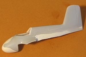
The incidence angle (the 'angle of attack' at which the wing is attached to the fuselage) looked seriously wrong: the trailing edge sits too high. Luckily, this was easy to change. I extended the sawcut along the outside panel line of the wing root almost to the leading edge. This allowed the lower wing to be twisted very easily. I laid it down on a flat plate, pushed the rear fuselage down some 2 millimeters, and superglued thin card in the saw cuts. Very easy
Then I noted why the fuselage looked so weird: it was way too high at the rear, which also made the tail look funny. I cut 2.5 millimeter off the top side of the rear lower fuselage. This improved things a lot
The rear fuselage modification also messed up my incidence correction. Luckily superglue breaks clean, so I could redo it easily
Next studied the rear fuselage. It still looked very unrealistic. Then I saw in the pictures that the letters 'KE+SW' are almost vertically on the rear fuselage. That means that the rear fuselage must have been very narrow. Thus I started a major scraping and sanding action to achieve it. I had to fill the fuselage interiors wit Milliput to prevent sanding through (and Condor's plastic isn't thin!). The lack of wing roots made the whole operation much simpler
The tail still looked funny. After looking at photographs, I decided that the trailing edge sweep angle should be changed. I cut off 1 mm at the base, tapering to zero at the top. I also slightly recontoured the tip
The fuselage spine is straight on the model, and slightly curved on the real one. I decided to cut away 1 millimeter just in front of the tail, and give the spine its slight curve. It also served to increase tail height a little, and further reduce fuselage height
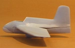
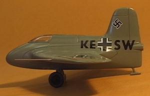
The canopy still didn't look right. I decided that it was too long. I glued 1 millimeter thick card to the rear side of the cockpit opening, and removed 1 mm from the canopy. Still not sure.. Only later I found out that two types of 163A canopies were used, and I probably looked at both types without realising it
The wing. That looked strange too. The wing area looked to be too large, too massive. Looking at in-flight photographs revealed that the chord was indeed too large. I cut off 3 millimeters of the trailing edge, and that looked much better. The trailing edges had to be thinned considerably
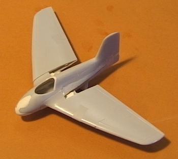
That's how far I've come so far. Still to be done: giving the wing leading edge a definite kink, restoring the wing roots, twisting the wings.
Surprised (to put it mildly) by the work needed to make a decent looking Me 163A, I started to ask around on the newsgroup rec.models.scale about the other available Komet models. This resulted in some interesting surprises. It turned out that the Victoria Products vacform was identical to the KPM vac (VP using more KPM masters or moulds). Then Frank Henriquez compared his VP vac and Condor injection moulded kits, and came to the conclusion that the Condor kit was based on the KPM/VP vac! The parts could be interchanged without any fit problems. The picture below (supplied by Frank) shows the similarities. That now leaves the Airmodel vac (very old), the Czechmaster/WK Models resin kit and the Aerodrom kit.
