AMT custom 1949 Ford
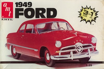
| When I saw a picture of a radically modified '50 Ford in the Belgian magazine Chroom en Vlammen (Chrome and Flames) (shown below), I knew I wanted to try to model this custom car. The car was widened, sectioned (taking a horizontal piece from the body) and chopped. I'm generally not a fan of custom cars, but this one I liked a lot. I found out that AMT had a model of a 1949 Ford, which was close enough for me. Later I found out that the 1949-1951 bodies are basically the same.
|
What does the kit represent?
The 1949 Ford was Ford's first all-new car after World War II. It was built in the following body styles:
2-door sedan aka 'Tudor Sedan'
4-door sedan aka 'Fordor Sedan'
2-door coupe aka 'Club Coupe' with a shorter roof, and front and rear bench seats
2-door coupe aka 'Business Coupe' with just a front bench seat, no rear seats
2-door hardtop aka 'Victoria' added to the range in 1951
2-door convertible
2-door wood-sided station wagon aka 'Country Squire'
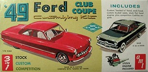
These versions could be ordered with the less-expensive 'Standard' ('Deluxe' from 1950 on) or the more expensive 'Custom' ('Custom Deluxe' from 1950 on) trim levels, making for example a 'Custom Club Coupe'. And this is what the standard version in this AMT kit represents. The first boxing is also clear about this (see below). On the MCM forum, 'Modlbldr' shows his conversion of a '49 Club Coupe to make a '50 Tudor Sedan. My boxing contained lots of other parts, that can be traced back to the five issues between the original and my boxing.
Kit history
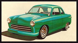
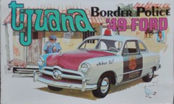
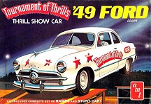
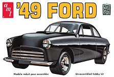
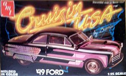
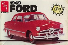
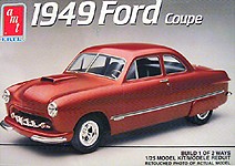
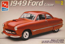
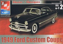
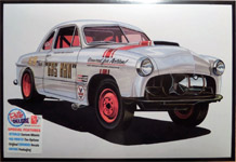
I compiled an overview of all boxings that I could find on Ebay and Google. After having seen all the versions in this kit's history, and their instruction sheets, I finally understand the purpose of many of the extra parts included in my AMT-Ertl #6580 edition. For example the second engine represent an early Cadillac engine that was popular among hot rodders in the early fifties. It's a first-generation overhead valve 331 ci engine from 1949. It was later enlarged to 365 and 390 ci until 1962. The kit engine has Tri-power and blower options. The Plastic model kit instructions site has a ton of old instruction sheets.
| 
| 
| 
|
| AMT T149-149
| AMT 2249-170 (1966-67)
| AMT T261 (1968)
| AMT T444-300 (~1973 ?)
|
| 
| 
| 
|
| AMT T290 (~1975 ?)
| AMT 2255 (1980)
| AMT-Ertl 6580 (~1985)
| AMT-Ertl 6805 (1991)
|
| 
| 
| 
|
| AMT-Ertl 6805 (1991)
| RC2-AMT 6805 (2005)
| Round2-AMT AMT601 (2008)
| Round2-AMT 1022 (2017)
|
Preparation
| This is the photo from 'Chroom & Vlammen' that was the inspiration for this project. If I was to start this build now, I would use CorelDraw to figure out the required cuts, but I did not use CorelDraw at the time. Therefore I did it the old-fashioned way shown below.
| 
|
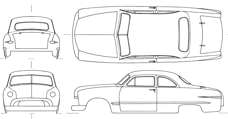
| Since it was my first custom conversion, I carefully studied how to cut the kit. I decided I needed drawings first. I photographed the model with the longest lens I had (400 mm) to minimize perspective problems. I then projected the slides on a piece of paper, and drew the model in ink on tracing paper, in four views.
|
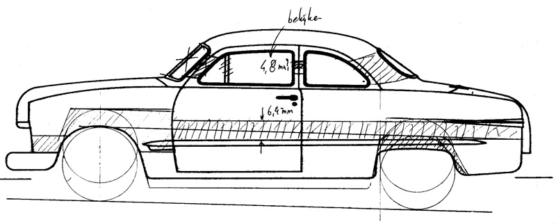
With copies of these drawings I devised where to cut the kit. I cut up one drawing to see where I best could make sawcuts. The exploratory sketching is visible in the picture. The real car's modifications were: a 120 mm roof chop, a 160 mm sectioning of the sides, and a 220 mm widening. I used the scaled numbers for my conversion.
Back then, when I started, I had no access to American car modeling magazines that described how to do it. For example Tim Boyd"s article 'Chopping the Mercury top' or
Anyone got a
link for how to chop an AMT 49 Mercury .
| 
|
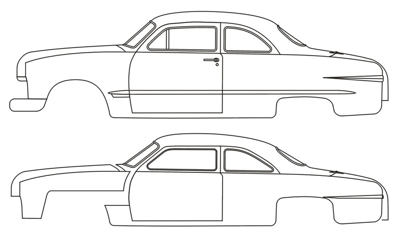
| Much later I copied the original ink drawing in CorelDraw. I then tried to capture my modifications in the same drawing, by cutting out 6 mm from the lower body, and around 2 mm from the top, plus moving the hood 3 mm forward.
|
| Next I overlaid the latter drawing over the real car's photo. The photo has too much perspective and is tilted a bit due the photographer's height to do this properly, but it's all I have. The agreement is so-so. I think it shows the trunk should be lengthened a bit.
| 
|
Construction
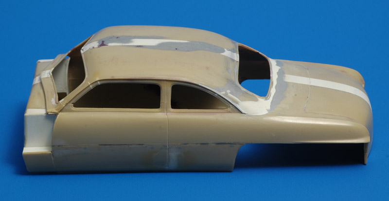
It was time for some serious sawing! In contrast to the careful preparations, I immediately cut the kit in 10 pieces. I then had quite a problem getting all the parts properly aligned again.. The photo on the right shows the cut in body sides (6 millimeters), still visible as a vague black line. I also cut off the lower rear part of the rear fenders. The top chop is some 5 millimeters (although I doubt that figure now, it's probably less).
Like on the real car, I bent the A-pillars backwards, so the windshield would be at a steeper angle. This was achieved by making '80% percent through' saw cuts, bending, and then fixing it with plastic card and superglue. The B-pillars were used as reference points for this, since these were only shortened. The C-pillars were not so easy. Prime concern here was to get rear window right again; the upper side of the rear side windows would be destroyed anyway. The complete C-pillar was cut out, modified and glued back as best as possible. A lot of sanding was needed to get it about right again.
| 
|
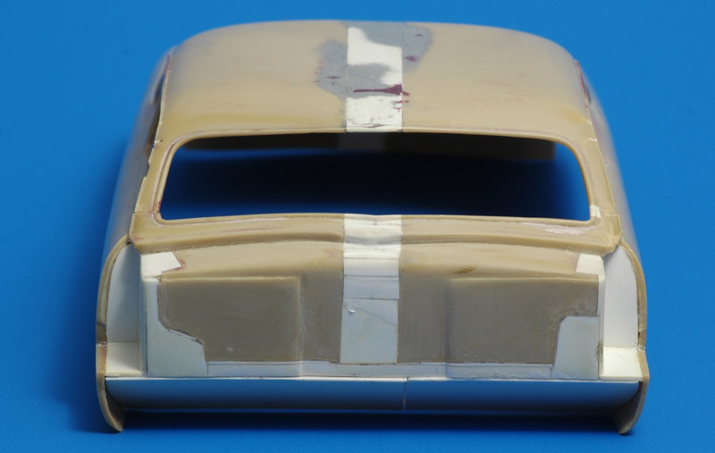
| Since I wanted to build a flip-top hood, I decided to cut off the front end. The front end consisted of the engine bay and the front fenders. The holes left by cutting off the front fenders are filled with lots of plastic card. More repairs to the firewall were necessary, and these too were made with plastic card and lots of superglue. Later a transmission tunnel will be cut out. The picture also shows the strip of 8 millimeters used to widen the car.
|
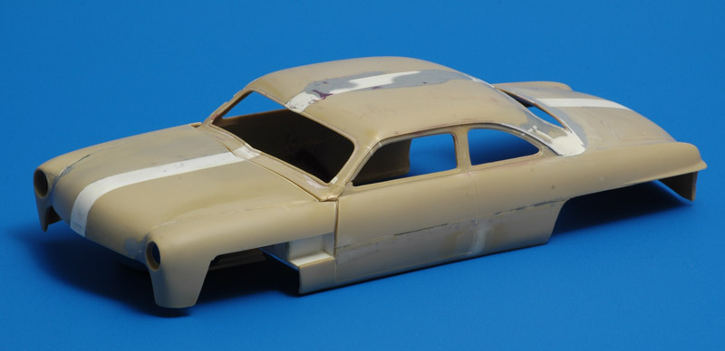
| The next photo shows the considerable mess put together again. It also shows the front fenders glued to the hood. The model still shows traces of the blue Tamiya putty, but it took me a while to learn that this doesn't work. The putty is much softer than the plastic, and sanding keeps creating shallow dents where the putty is. I then switched to super glue, my favorite filler since some time. This improved things a lot. It has been quite a drag to get the body smooth again, but I'm slowly getting there.
| 
|
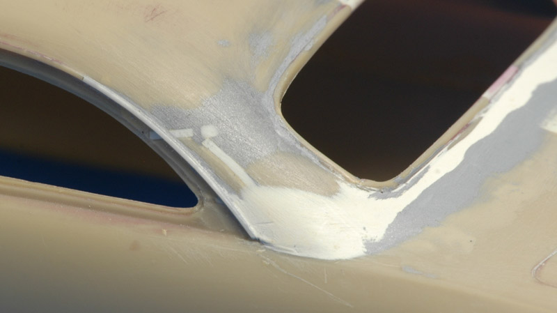
| The A, B and C pillars still require a lot of work, but with a lot of patience it can be done. The rain drip rail was recreated using thin plastic strip from Evergreen. The rear window trim still needs some work.
|
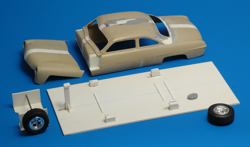
| While working on other car models I learned the value of jigs, and I decided to build one for this model too. It's basically a large sheet of 2 mm plastic card, with raised supports for the body, and a high support for the hood. I also built a simple axle holder, to study the wheel positioning.
| 
|
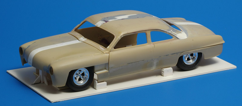
| And this is what the model looks placed on the jig, with wheels. I gave the body a small forward tilt by using different heights for the supports front and back. For the first time I saw that playing car designer is not as easy as it looks.. The model looks kind of weird..
|
| A side view possibly helps in determining what to change. Maybe the wheels/tires are too big? Possibly the rear wheels need to move forward? The real car had its trunk lengthened 12 mm (in scale), maybe that helps? Not an easy job, since the rear of the car tapers quite strongly. Let's first finish the current modifications.
| 
|
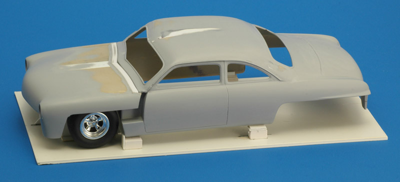
| I decided to apply a partial coat of Mr Surfacer to see how the model looked in a neutral color. For the first time I noted that the hood looks strange, since it's now wider than long. Therefore I started adding 1 x 1 mm plastic strips at the rear of hood to gradually make the hood longer until it looks natural. At the same time I realised that I now need to lengthen the trunk too, and this will be very complicated. I also found some waviness in the roof that required more sanding.
|
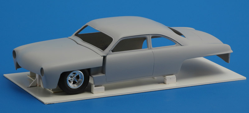
| After some more sanding and layers of Mr Surfacer, here's another look with the longer hood. I'm still not sure about the shape. Maybe the opening ahead of the door (like the real car) doesn't work.
| 
|
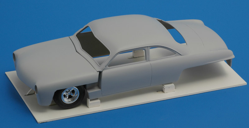
| Another view. I'm not sure which angle to use to judge the shape. I don't like the bird's eye view because that's not how you view real cars. But model cars are often viewed like this.
|
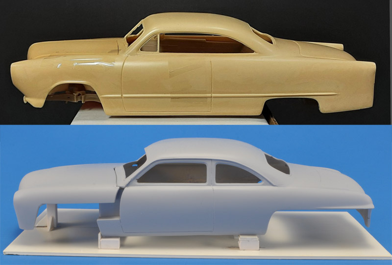
In 2025, I saw this interesting resin body by Modelhaus on the MCM forum, in the long-running Whats your rarest, hard to find, never seen before, Cant get no more, model car kit thread. It modeled after a 1:1 custom car, see Buster Litton Panoramic Ford webpage. The model photo was kindly supplied by Mike Hastie.
For me, the interesting difference is the absence of side window framing. It makes the body more 'airy', but maybe the body with window frames looked more 'gangster' / 'bad' in a way, for lack of a better description (non-native speaker here). Especially with tinted windows.
| 
|
Flathead engine references
The model's V8 flathead was Ford's last flathead V8, built from 1949 to 1953, and it was a 24 bolt head design. It had a 239 cubic inch capacity, delivering 100 to 110 hp. See here for Vanpelt Sales: specs and drawings. Most other references consist of Youtube videos:
Here's another stand-alone Worn out Ford Flathead model. If you want to build a non-V8 powered Ford, there an aftermarket Kitchen Table Resins Ford Flathead 6 Kit available.
Flathead engine construction
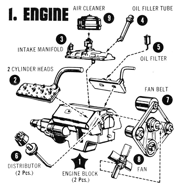
| I decided to build the kit's flathead V8 as a separate project, possibly as a stand-alone model. I don't intend to build a 100% accurate replica, for that I would need access to a real one. Just as an example, it's well possible that the engine is undersize to make it fit the model's engine bay. Instead I'll do my best to improve the details the best I can. It's also an exploration of what is possible with such an engine.
The flathead in this AMT kit is the 239 cubic inch 8BA, built from 1949 to 1953. There's a slightly different flathead in the Pro Modeler / Revell 1948 Ford Convertible / Coupe from 2007. It's probably the earlier '59A' or '59AB' engine, with cooling water exhausts in the middle of the heads. It is slightly better but still not perfect. It has separate exhaust manifolds and the cross-over pipe, but the water pumps are like the AMT 1949 Ford, very simple and does not look like the real thing.
Shown here is the single instruction step from the instructions of my kit. No paint instructions are included, leaving a European modeler like me in the dark about the colors.
|
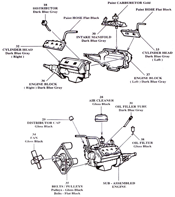
| Luckily I found the instructions from a later issue, with paint instructions. But still I need to check photos and videos to find out the true colors.
| 
|
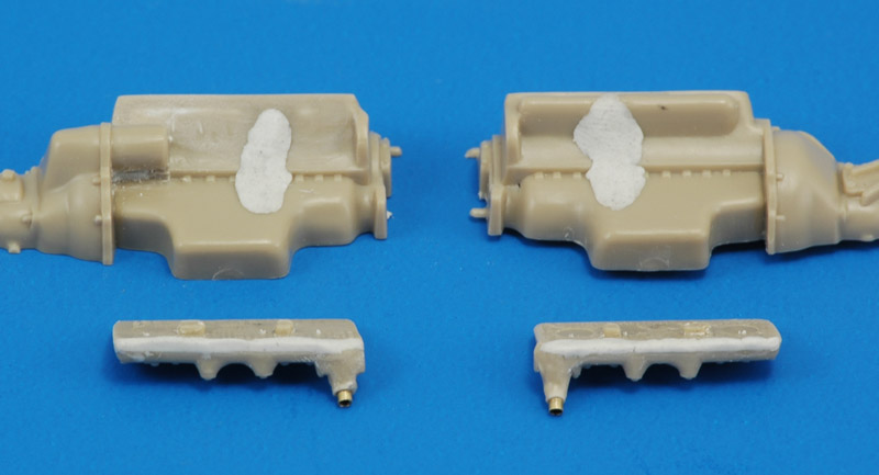
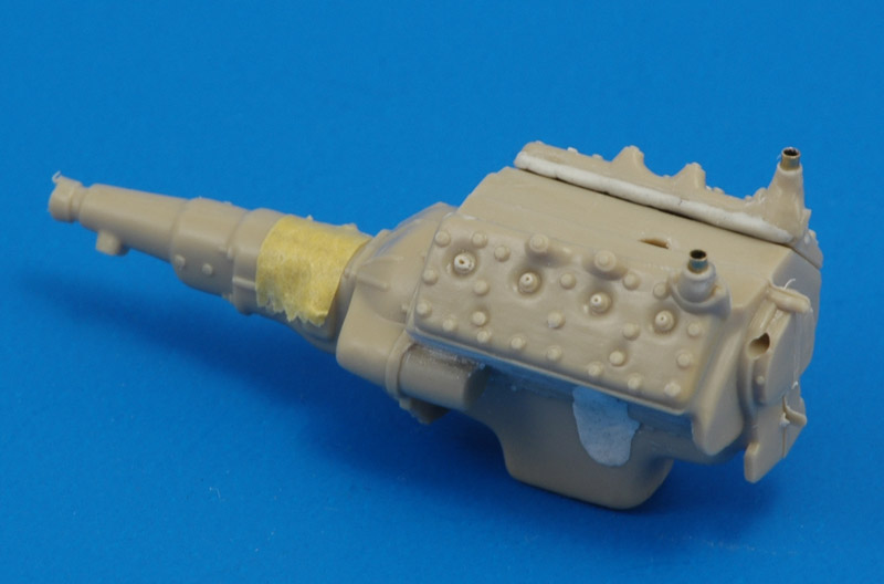
| I started with filling the large openings in the side of the engine block, that AMT made to run the metal front axle through. The exhaust is represented by a raised area on the block halves. I removed it on the right side, and I cut almost through the plastic there. You can now see the white Apoxie that I used to back it up on the inside. On the cilinder heads, I filled a rough notch at the inside edge with Apoxie.
|
| The parts shown above are here seen assembled dry. I removed the coolant hoses from the cilinder heads, and installed Albion 1.2 mm tubes. I drilled out the spark plug covers with a 0.3 mm drill, but I'm not sure yet what kind of spark plug leads I will use.
| 
|
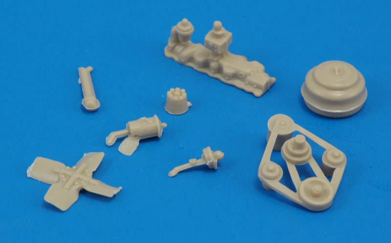
| The other engine parts are shown here. Most parts need some clean-up, and a thinning of the belts is also in order.
|
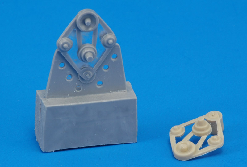
| I decided to make resin copies of the fan belt part, so I could separate the parts and build better pullies. To cast a single-piece mold it required a paper 'mask' to fill the opening.
| 
|
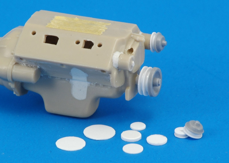
| I cut discs of 0.3 and 0.75 mm thickness with a Waldron punch and a circle template, and assembled them with the front parts of the kits pullies. I sacrificed the original pulleys + belts part by gluing the water pumps to the block, and then cutting off the remainder of the part with a JLC saw.
More work on the block itself: the Apoxie that filled the axle hole was filed and sanded down, and three exhaust ports were drilled in the side of the block. I drilled the head's plug ports through the engine block, so I could use a long length of ignition wire.
|
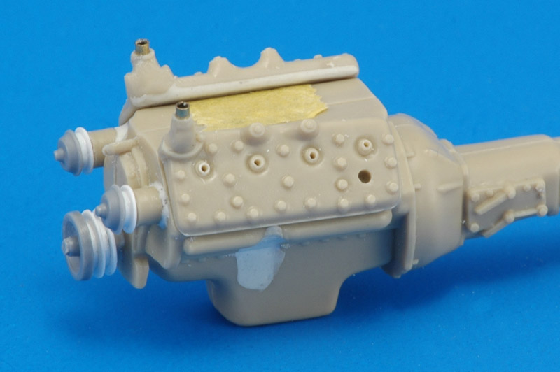
| The above leads to the following status. I see that the pully alignment needs a bit more work. The heads were moved slightly aft compared to their original fit. The photo shows the original AMT exhaust manifold still in place on the left side.
| 
|
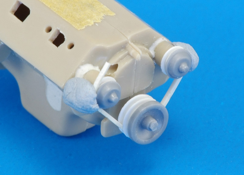
| Here's a first attempt at making a belt around the pullies. I used a 0.6 x 0.6 mm plastic strip. Of course it broke when bent around a pully, but some Tamiya Extra Thin made it pliable. After the generator is added to the engine's valley I can try to make a full belt. Another belt is required to drive the cooling fan.
As for the belt width, I found a lot of numbers, but 5/8" was mentioned often for a '49 8BA with the twin belt system. That makes for 0.64 mm, therefore my plastic strip choice was correct.
|
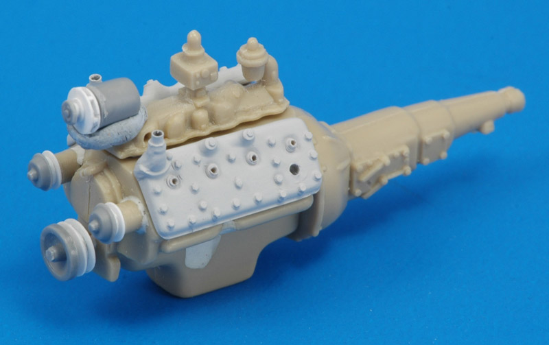
| A little more progress, with the generator pulley done. It is glued on a radial cooling fan, that is butted against the kit part. Maybe I'll replace the latter with a cilindrical piece, since the kit part has a mold draft angle. I also started painting parts in gray paint to judge the build quality.
| 
|
I wondered whether I was spending a lot of time detailing an engine that potentially was vastly undersized to make it fit the model's engine bay. Popular American V8 engine dimensions, for a generic Ford flathead:
|
| 1:1 size
| scale size
| measured size
| comments
|
| Length from rear mounting surface to water pump pulley
| 30"
| 30.5 mm
| 29.1 mm
|
|
| Width outside of valve cover to outside of valve cover
| 26"
| 26.4 mm
| 20.8 mm
| listed dimension appears to be excessive
|
| Height from bottom of sump to highest point of intake manifold
| 22"
| 22.4 mm
| 22.7 mm
|
|
Another source has different numbers: Engine dimensions for the engine swapper, again for a generic Ford flathead:
|
| 1:1 size
| scale size
| measured size
| comments
|
| Overall length, bell housing not included
| 30"
| 30.5 mm
|
|
|
| Width including exhaust manifolds
| 24"
| 24.4 mm
|
| listed dimension appears to be excessive
|
| Height including air cleaner, oil pan depth and sump location may vary
| 26"
| 26.4 mm
|
|
|
The Ford museum is another source. Ford V-8 Automobile Engine, 1937 data:
|
| 1:1 size
| scale size
| measured size
| comments
|
| Overall length, including bell housing and gearbox
| 42.50"
|
|
| not usable
|
| Width including exhaust manifolds
| 19.75"
| 20.1 mm
|
| listed dimension appears more reasonable
|
| Height over all
| 33"
| 33.5 mm
|
|
|
My provisional conclusion is that length including water pump pulley is 30", width including exhaust manifolds is 19.75", height has too many variables. The kit's engine matches these two figures quite well - I'm happy with it, it's not undersized.
Modeling links
Return to models page


