1/72 EA-3B fuselage sides


During my aircraft spotting days, one of the highlights was seeing Skywarriors from VQ-2 at Rota. I wanted to build an EA-3B, but that version is not available as a kit. I decided to design the fuselage sides as a first step to build an EA-3B.


Reference material

Lacking drawings, I tried to find photos that showed the windows and the door. This photo formed the start of my analysis. I used CorelDraw to draw the details over the photo, and scaled the photo using some panel lines on the front fuselage, the main landing gear door outline and the speedbrake.
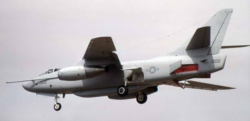
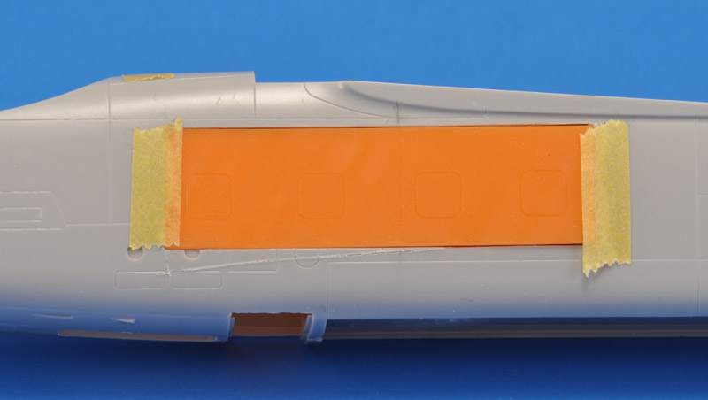
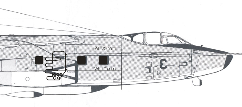
Next I scaled the drawing from Aerograph page 80 to 1/72 scale, and copied the above on it. I calculated that the aircraft in the above photo had a 25 degrees 'bank' angle, leading to a cos(25)=0.906 shortening of the vertical dimensions. Therefore, I compensated by a 10% vertical enlargement. This gave me almost perfectly square windows, always a nice check for your work.

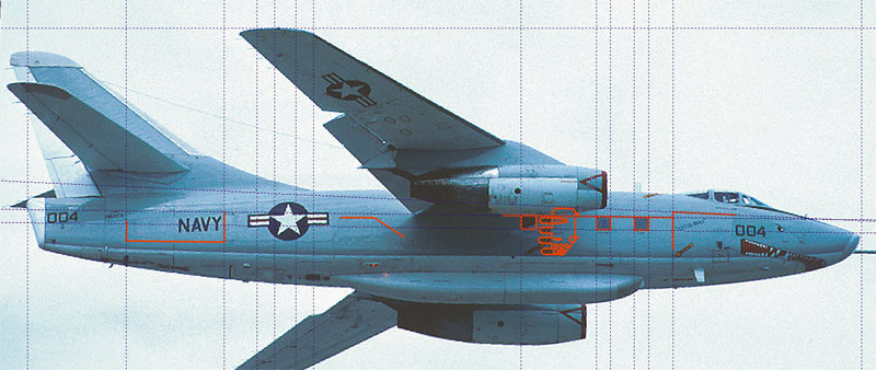
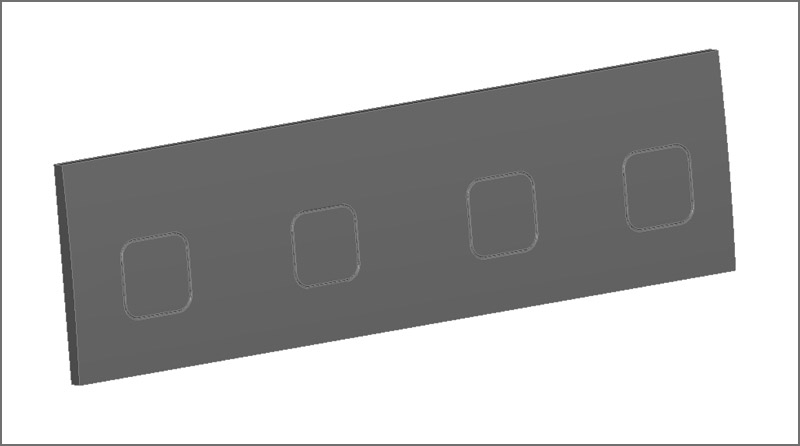
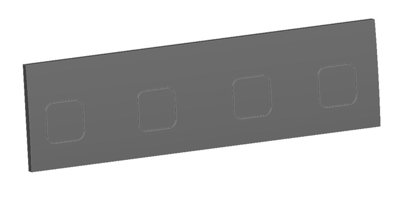
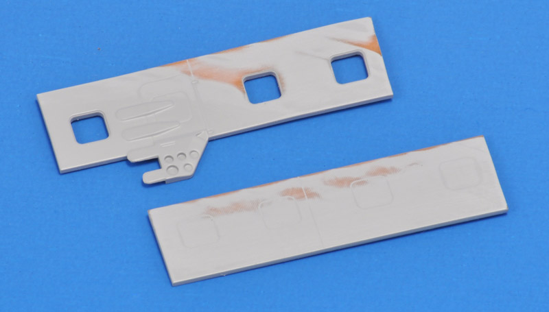
'My' windows were a bit smaller than those of the drawing, but the positions agree fairly well. I calculated a size of 14.7" and rounded it off to 15". Likewise, I calculated that the rounded corners were 19% of the width/heigth, and rounded that off to 20%, or 3".
Now I had something to print and stick to the model, for a visual judgement. The 'waterlines' (from the bottom of the fuselage) helped to position the strip. I was surprised how low the emergency exit went on the fuselage. I guess the lower part is not actually covering the door opening, but just a blast deflector for the crew jumping out.


3D CAD

Based on the 2D drawing I made a 3D CAD model. It features a very slight bulge (large radius) in the the fuselage side, that you can see on the right edge of the part. I measured that radius on the model itself. The three window openings have coamings to mount transparant parts.

The door was by far the most laborious part, with chamfers everywhere and in all directions, a few of which I could not incorporate. It needs some more fine-tuning, especially in the extra thickness of its lower part. It looks extra thick because there's no fuselage in the model.
For the opposite side I plan a similar part, featuring only four closed windows. But I am not 100% sure that all EA-3Bs had these windows. Possibly it depends on what version they were originally built as.
Tommy 'Tailspin Turtle' Thomason kindly sent me copies of Douglas factory drawings, and I used these to revise the window position and size (from 15 to 16"). The door is not yet updated, but I see one small went missing (part of one of the 'fingers' over the plugged window).

Door handle is missing.

Hinges are missing.
In the mean time we've learned that probably all 'Versions' A-3s were built with four windows on either side, I proceeded with the left side too. It's basically four scribed lines. But since I'm no good at scribing, I would rather install a part like this.


3D CAD restart

The project was dormant for three years, because I less than impressed by the outsourced 3D printing results. But with that problem resolved, I updated the models. A vertical panel line was added just ahead of the emergency door, and I increased the width and depth of all panel lines. I also added hinges for the emergency door.
Previously I had designed the door as a flat part, now the upper half has the same curvature as the rest of the fuselage. The lower half of the door should have a curvature too, but that exceeded the capabilities of me as a CAD designer. I will bend that part the old-fashioned way, after printing.


3D printing

Here are the first printed parts. The panel lines looked perfect! The parts were thinner than expected. Maybe I'll beef them up a bit for the next try.
I cut a rectangle from the right fuselage side, and then noted that the print had a deformed front end. The rest looks very good I think!
The insert for the left fuselage side barely shows the four windows. It looks like the panel line width and depth match that of the kit. A coat of paint will show that better.
Four light coats of Tamiya Surface Primer revealed more printing flaws than I had seen before. The panel lines probably need to be deepened, since the required primer fills them partially. Another 3D printing lesson learned.


To be continued..


Return to models page