Italeri 1/72 Super Etendard
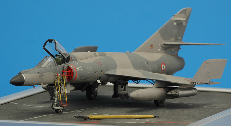
| One of my earliest models is this Italeri Super Etendard. I bought it in 1987, after reading a review in the German modelling magazine Kit. I finished it just in time for the Dutch IPMS Nationals 2002. Serious modellers will understand that some (or most) models take a long time to finish :-)
|
The kit
The Italeri model was, and still is, a great model, with very fine engraved panel lines, and almost flawless fit. Subsequent Italeri kits were definitely not as nicely detailed as this Super Etendard. The model has a separate refuelling probe, separate arresting hook, well detailed landing gears, detailed main landing gear bays, two types of fuel tanks (two 600 liter and one 1000 liter), the Exocet missile and two Magic II air-to-air missiles with launching rails. The gun ports are way too shallow however. An example of the level of attention is the two different canopies supplied. On the full-scale version, the canopy partly falls into a recess, and therefore Italeri supplies an 'open' and 'closed' version of the canopy. The cockpit interior is very basic though. The decal sheet contains an Argentine aircraft, and a French aircraft in the old glossy blue/white color scheme. The box has painting instructions for the later French scheme too, but the decals for this scheme are very incomplete. I never checked the dimensions and shape of the model, but in 2011 a shape comparison was added to this page (see below) which revealed some shape problems.
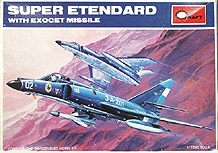
The version by Academy from Korea is probably much better known than the Italeri version, and Academy still produces it. I compared the Academy kit to my Italeri model, and it is 100% identical, down to the smallest details and it the same small problems. A Scale Model Aircraft Kit Reviews article (via the Wayback Machine) of the identical Academy model has some more comments. Sunny Tri-S was a Japanse distributor for Korean model kit companies, and issued the Academy Super Etendard model in their own box (catalog number P2). On Ebay I also found a Minicraft boxing, that shows the first Minicraft logo. In 2012, Academy reissued the Super Etendard in a "2011" edition with Cartograph decals for the Libyan war (catalog number 12431). It is not clear whether extra parts are included to make it a true Super Etendard Modernise (SEM) or any of the modern weapons and systems are included.
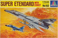
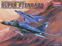
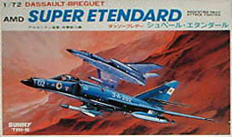
The four boxes shown below are just a part of the various issues. See Scalemates for a complete overview.
| 
| 
| 
|
| Italeri 152
| Academy 1602
| Sunny Tri-S P2
| Minicraft 1602
|
Other kits
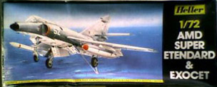
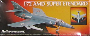
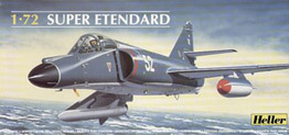
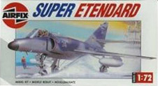
Another Super Etendard model in 1/72 scale is available from Heller and Airfix (both were owned by Humbrol until 2006). Compared to the Italeri/Academy model, the Heller model's shape is better (see analysis below), the main wheels are very nice, it has a correct fuel tank, but it has raised panel lines, too small airbrakes, no wheel bay detailing, no separate arresting hook or refuelling probe. A review can be found on the Scale Model Aircraft Kit Reviews site via the Wayback Machine.
| 
| 
|
| Heller 360
| Heller-Humbrol 80360
| Heller 80360
|
|
|
|
|
|
| Airfix 3060
|
|
Kit comparison
Years after finishing my model, information surfaced that allowed a detailed comparison of the Academy and Heller models. With thanks to Peter Rozendal, François Poulic and 'AV O':
the mid-fuselage width differs greatly between the models. The Heller model is around 5 mm narrower, with 5 mm longer wings, resulting in the same wing span. The Heller flaps are also longer, which explains my problems with the flap decals as reported below. I compared my finished model with photographs that show the fuselage width, see for example this photo. The model definitely lacks the real aircraft's 'area ruling', a narrowing of the fuselage at the wing position, coke bottle style, for lower transonic drag. The Heller model is better, but still doesn't show an area ruled shape
the rear fuselage, aft of the wing, appears to have the correct width on the Italeri/Academy model, and appears too narrow on the Heller model (resembling an Etendard IV)
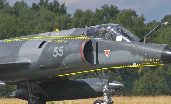
another shape problem of the Italeri/Academy kit is the nose section: it should angle down, most likely for carrier landing visibility, and this angle is not represented properly. Maybe 2-3 degrees are missing (see photo below).
the wing leading edge has a kink near the root. It is definitely too small in the Heller model, and maybe too small in the Italeri/Academy kit
reportedly the Italeri/Academy windscreen and canopy are too wide and flat compared to the real aircraft
the air intakes have some shape problems. They are too cylindrical, and should bulge more (see photo below). It is also reported that the intake is too low on the nose side, but I don't see that (yet).
Construction
I don't recall the smaller details of the initial construction 15 years ago. I remember a small step in the underside of the front fuselage, and small problems lining up some of the panel lines. But otherwise the fit was excellent. Back then I wanted to do the old French Navy scheme, consisting of gloss dark blue on top, and gloss white below. I started with white as an overall base-coat, but my airbrushing skills were not up to snuff at that point. I created a completely orange-peel covered Super Etendard. A bath of caustic soda was prepared, and the paint was removed. The model was returned to its box, for more inspiration at a later time. That moment came years and years later, when I was finally able to buy Carpena's (or Colorado's) reprinted Super Etendard sheet, number 72-56. This is a fantastic sheet with all stencils, and about enough numbers to build a carrier full of Etendards. The instruction sheet didn't mention about half of the decals however, but a couple of hours of research solved most problems. In the mean time I had also decided to switch to the later camouflage consisting of two greys. Between that first airbrushing attempt and my renewed interest, my building skills and quality requirements had increased considerably. So first I had to check what needed updating or rebuilding.
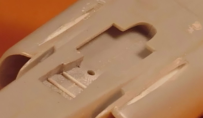
While studying a Super Etendard up close at an air show, I noted that the gun ports were much deeper than the shallow dents on the Italeri kit. It's a difficult problem to solve. Initially I had no idea how to build them. I tried drilling, but there's no room for the drill bit, that close to the fuselage. Then I thought of gluing a small plastic tube (internal diameter about 1 mm) half-sunk in the inlet, and sand that down at a very shallow angle until it gave the required long elliptical shape. But it would be very difficult to glue that tube at the right depth. Too deep, and the port will be too small, and vice versa.
I decided on another technique. First I cut a slot in the lower sides of the intakes, and glued a strip of plastic card inside the inlet, to close the slot. I then filled it with Milliput, and pressed a wet piece of 1 mm diameter steel wire in the soft Milliput. The wire was removed and the Milliput left to harden. This procedure allowed the depth of the gun through to be judged fairly accurately. The next step was an experiment. I coated the same piece of steel wire with wax, and placed it back in its slot. Then I applied numerous coats of CA glue. After the CA had cured completely, the steel wire was rotated until it snapped free, and then removed. The CA glue was then sanded, and a nice elliptical opening appeared. It's difficult to see in the photo, because it's nearly impossible to photograph. I decided against a reconstruction of the nose landing gear bay, which is quite shallow. I merely added walls from thin plastic card, and declared it finished.
| 
|
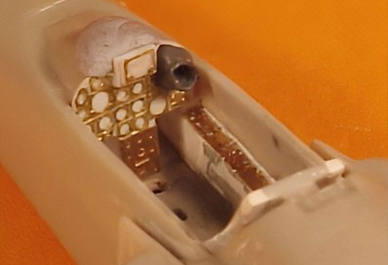
| Then there was the cockpit. The caustic soda bath had stripped away my carefully painted instruments. I decided to do a complete rebuild of the cockpit. I should mention that no photo-etched sheet was available then, although Eduard released it shortly afterwards, early 2001 or so.
A study of (rare) cockpit photos convinced me that Italeri's instrument panel was placed to far aft, leaving not enough room for the seat and stick. Measurements of the photos made me decide to place the IP two millimeters forward, I decision I still like. Next I cut a piece of 0.3 mm plastic card to the correct shape of the panel, this involving lots of fitting. With the panel's shape now defined, I made a 10:1 sketch of it, and then sketched the instruments on it as best as I could, using the single available photo. A ruler and a circle template were then used to finalise the drawing. A Reheat 'Instrument Bezel' photo-etched sheet provided the required instruments. An hour later I had my Super Etendard instrument panel! In the photo it is held in place by a blob of Blu-Tack.
Later I added a piece of Eduard F-100F photo-etch at the bottom of the instrument panel. The radar scope rubber thingy was sculpted from Milliput, with a copper wire ring at the end. The HUD base consists of two small pieces of plastic card, with a suitable Reheat piece glued on top. The photo-etch for the side consoles was stolen from an Eduard F-111E set. I still need to add longerons along the cockpit opening and some side-wall detailing. But having only one clear photo doesn't make this simple. Also visible in the photo is that I made the plate at the back of the cockpit square instead of rounded.
|
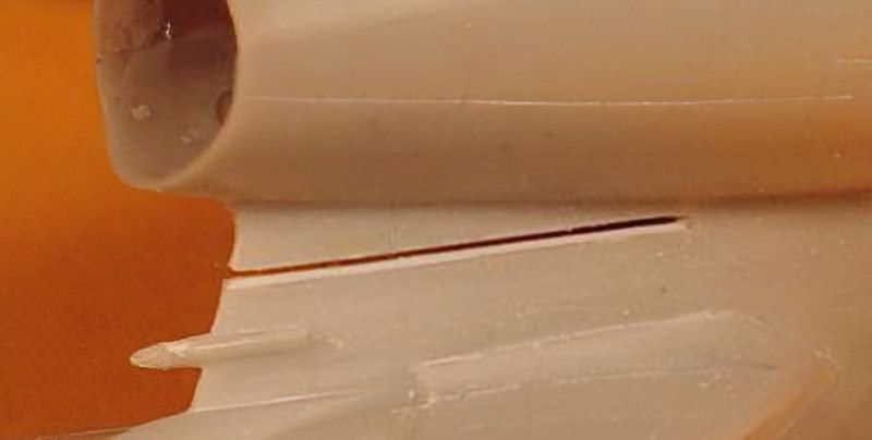
| A small modification is a saw cut just above the rear fuselage. On the real aircraft the rear section of the fuselage can be taken off for engine removal. This also results in a gap with the rest of the vertical tail. Italeri just shows a panel line there. I don't remember whether I made the saw cut just a little too low, but just above it a wide panel line remained. It looked really strange, and I decided to fill it with a small piece of plastic strip.
| 
|
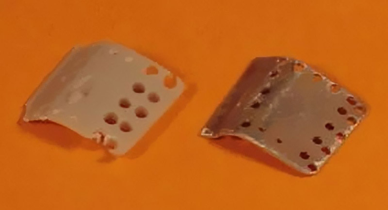
| Many moons ago I had glued the main and nose landing gear doors and the speed brakes into the lower fuselage. Due to my limited skills back then, the doors were not flush with the fuselage however. A major sore to the eye. And my new references showed that the doors were sometimes open, instead of closed as at air shows where I had seen the real thing. But all the parts were glued solidly to the fuselage, with few possibilities to grip them for removal. This problem 'solved' itself though.
I have a motor tool, but I don't use it much. Due to this lack of experience, I thought it would be a nice idea to drill out the holes in the speed brakes. Bad idea. After some drilling and melting I had a thoroughly screwed-up speed brake. And even with properly drilled holes, the speed brake would have looked unrealistic, since the thickness of the part shows very well. This was quit bad, because I didn't know of a simple solution for this mess. One advantage though was that the drill had broken the speed brake free from the fuselage.
|
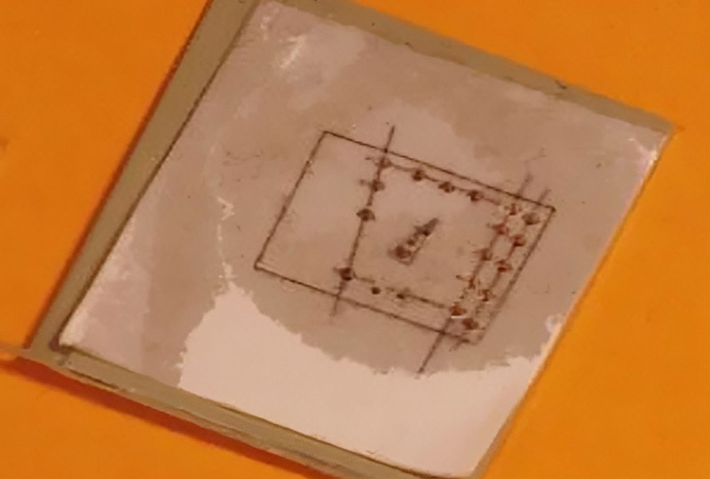
After some thinking I decided metal would be the best way to go. But how can one drill such tiny holes accurately in such a difficult pattern? I had to make a small CAD drawing of the speed brake, using the kit parts dimensions, and a correct hole pattern from a photo. Because of the perspective of the single photograph I had, this required lots of calculations. But after two frustrating hours, I had my pattern.
I glued the paper pattern with some CA to a piece of 0.3 mm aircraft grade aluminium, an drilled 0.8 mm and 0.5 mm holes in it. Then the part was cut along the lines, and bent carefully into shape. The result can be seen above. Actually it is the prototype, and I made two real ones the next day. It looks like it is made of brass, but the color results from a very tough primer sprayed onto the aluminium. The shape of the prototype part is not completely correct by the way; it has a flare at the left side, which should be removed.
| 
|
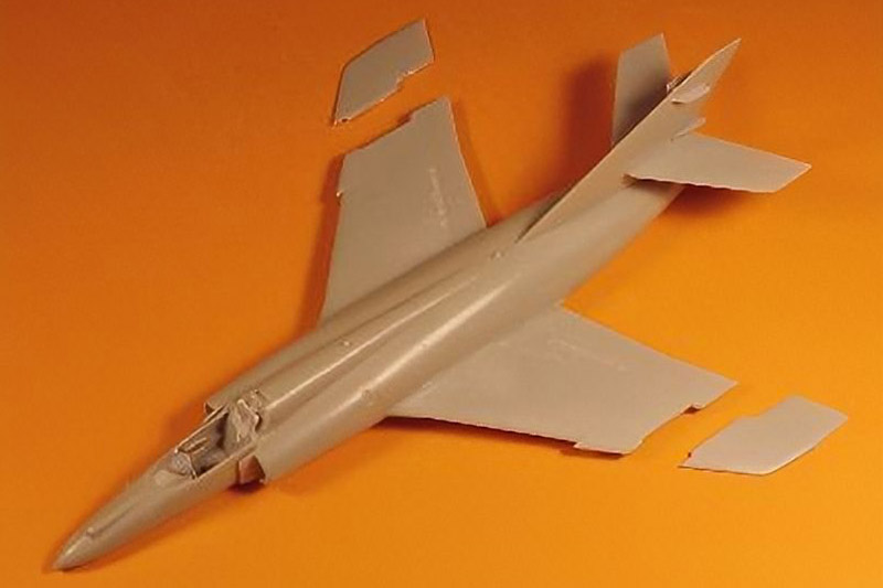
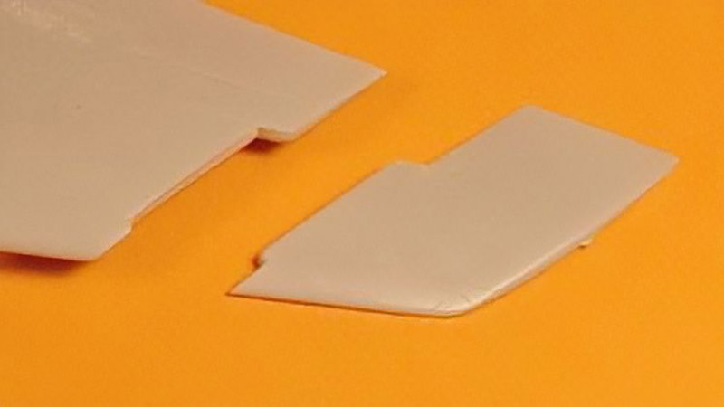
| I had decided to 'park' my Super Etendard model on a piece of carrier deck. This meant another rather major modification of my 'almost-finished' model: the wing tips had to be sawed off. The operation was a combination of sawing with a razor blade saw, and scoring with a needle of the middle section. The scoring also resulted in some deeps slip marks, but these were quickly repaired with some CA glue. After the surgery, the model looked strange to me, having seen it always with the complete wing. But I think it will make the model more interesting.
At this point I made an annoying discovery: the right wing had zero dihedral, and the left wing some 1-2 degrees of negative dihedral (anhedral). Oops! I think I just glued them to the fuselage back then, without checking alignment. Something had to be done here. My sources told me the wings should have 3.5 degrees of anhedral. That meant removing both wings .. The razor saw made it quite easy though. Using a simple jig I was able to put them back on at the required angle. The anhedral makes the model look slightly more aggressive.
|
| A close-up view of the cut-off wing tip. The resulting openings in both the main wing and the wing tip were filled with Milliput, and coated with CA glue. They are now completely flat and featureless, until I find out how the wing break should be detailed. Happily, some fellow modellers from France came to the rescue!
| 
|
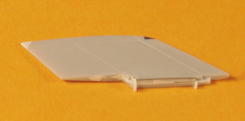
| The foldable wing tips required hinge detail. Fortunately the Super Etendard wing fold is very simple compared to (for example) that of US Navy aircraft. It has little more than two hinges. I detailed it with plastic strip and card and stretched sprue, using the single wing fold photo I have ever seen. This photo was kindly supplied by Pierre Henri Baras of the excellent French Fleet Air Arm web site. Visible in the photo on the right is the wing tip light that was cut out and replaced with a piece of transparent colored plastic. The tip shows a repair with plastic card, the model was dropped years ago.
|
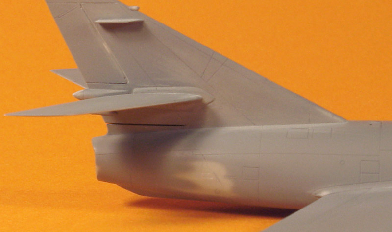
At this point the model was ready for painting. I used the lighter of the two camouflage colors (~ FS 36270) as a base coat for the model. Humbrol 126 was used for this. The base coat was mainly meant to check the building quality. I was very pleasantly surprised by the looks of the freshly painted model; Italeri's engravings are extremely nicely done. The base coat did a very good job of revealing all small building errors. I think I found some 30 all over the model. These were attacked with sanding paper, scribing knife, paint and super glue.
Some of the corrections can be seen in the photo. The rear fuselage had a crooked panel line, which was corrected with super glue; the leading edge of the fin needed more attention, and the panel line at the wing-fuselage connection required some sanding. A small problem was also found on the left rear fuselage, where it had a flat area. I checked this on a built but unpainted Academy model, and it had the same flat spot, so it seems to be a problem of the kit. Some delicate sanding and repainting (to build up thickness) solved it.
| 
|
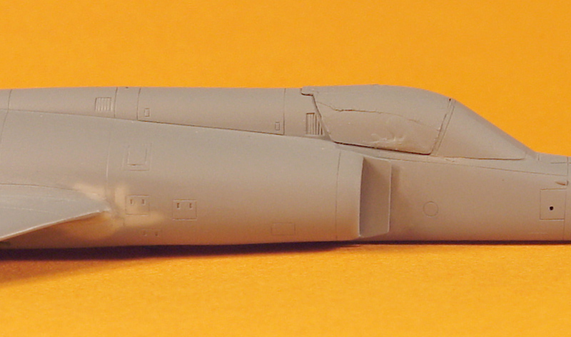
| The front fuselage shows some more corrective work in progress. The windscreen had been glued to the model before painting, and the clear parts of it were covered with adhesive aluminium foil (see the Cheap Chocolate Foil page). One of the two canopies supplied by Italeri was used to roughly close the cockpit during painting. It too was covered with adhesive foil.
After the first set of repairs, I sprayed a second base coat. This revealed that still a number of smaller building errors remained. These were corrected again. That finished a most important phase of the model's construction. This correction phase is rarely shown in construction reports. Yet I think it is one of the most important steps in building a good model.
|
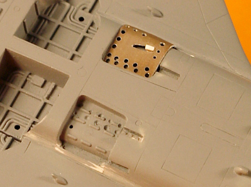
This photo shows some of the work on the lower fuselage. The speed brake wells were narrowed a little by gluing a piece of plastic strip on the outboard side. It required some extra sanding after the first base coat, and now the white plastic is peeping through the paint. The outer arm of the speed brake was moved inboard a little, and this also meant moving the arm well with card and cutting. The lower speed brake well shows extra holes, these being the result of my careless drilling attempts earlier. In the top speed brake well the metal replacement speed brake is visible.
The main landing gear bays were detailed a little extra with some plastic strips. A final detail visible in this photo is the catapult bridle hook on the lower wing surface. Italeri molded these as indistinct bumps, but some carving turned them in realistic hooks.
| 
|
Painting and decaling
After three rounds of base-coating, checking and repairing, the model was declared fault-free and ready for application of the camouflage. The Carpena decals played an important role here. The serial numbers on the real Super Etendard are in the light camouflage color, most likely achieved by masking during camouflage application. Thus the light camouflage color on the model needed to match the decal color very closely. I also needed to learn how to apply Carpena decals, which I used for the first time. Note that the serial numbers on this Carpena decal sheet have a decal film that is only just a little larger than the ink. I wish more decal manufacturers could do that!
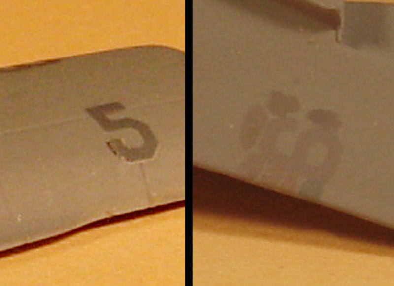
I started with an attempt to simply apply a decal to a polished piece of Humbrol 126 painted surface on a test model. The '5' decal shows the result: it silvered around the edges, and it adhered very, very badly, as can be seen by the lifted part. This was scary! For the next decal I tried my usual recipe: wiping off the decal glue, and using Future floor polish as the decal glue. The results were perfect: the decal conformed to the surface perfectly, and no silvering occurred at all. With this technique I applied a light-colored serial number decal to my Humbrol 126 base color. The '6' decal shows a slight but clear color difference. After seven attempts at mixing a matching color I found a good match, using H126, H125 and H133 in a roughly 10:2:1 ratio.
| 
|
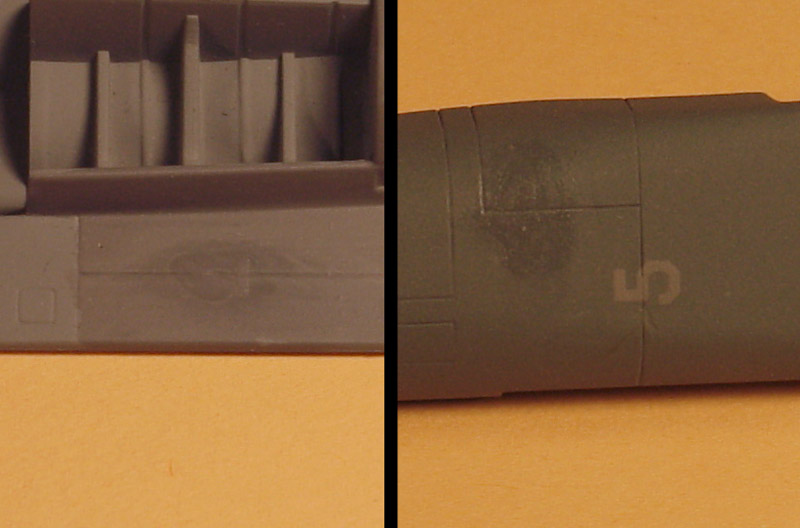
| I painted a large surface of a test model with the paint mix, and applied a '4' decal. The match was more than good enough for me, and the light camouflage color was now defined. The dark camouflage color was much easier: it turned out that Humbrol 125 was a perfect match. The right side of the photo shows a number '4' decal applied to a test model in H125. The glossy patches around the decals are remains of the glossy Future. A satin clear overcoat makes the decal blend in perfectly, as shown by '5' decal on the right side.
Note that I usually do not match my model colors to decals - they are usually not reliable. But because of the serial number issue, it was necessary here. The resulting color is slightly browner than the specified FS 36270, but very close.
|
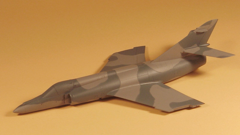
And then, after so many years, the camouflage could be applied! I first sprayed the complete model in the light color. After a quick drying session in the oven at 50°C, I laid down the camouflage pattern using Blu-Tack. I followed a pattern that I derived from my slides of Super Etendard with serial number 31, that I photographed at an air show in 1991. After 1.5 hours of fiddling, the Blu-Tack was in place, and I filled in the rest with Humbrol Maskol. I also used Frisket film and Tamiya tape to mask the area around the horizontal tail root (more on this five photos down). Then I sprayed H125 all over the model. After some 10 minutes I removed the masking, in order to satisfy my curiosity and to be able to correct small mistakes with a thinner-soaked cotton swab.
The result can be seen here. Technically it was almost perfect, but somehow I was not too impressed with the result. The color combination looks a bit strange to me, and it looks highly unrealistic now. But this happened too with my Stuka, so I should not worry.
| 
|
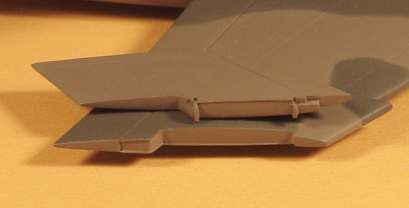
| This photo shows the end result of the wing hinges, on both the main wing and the wing tips sides.
|
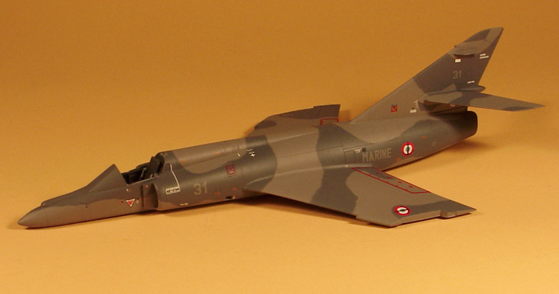
Next were the decals. In one weekend of work, all of them (I counted roughly 100) were applied. It was quite a job, especially because of all the small stencils. The serial numbers were difficult to apply. The number '3' is rather unstable because the film only covers the ink (which is a very good thing in itself), and aligning the '3' and '1' in a rapidly drying puddle of Future wasn't easy either. But is was all worth it, after a layer of Humbrol 135 satin clear it looked fantastic.
I made number 31 because I made several good photos of it at the Valkenburg air show, 5 June 1992. I prefer to build aircraft that I've seen in the flesh.
| 
|
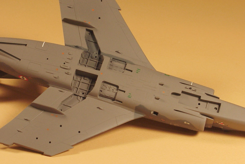
| A view of the decals on the lower side. The decals worked really well on this part of the model too.
|
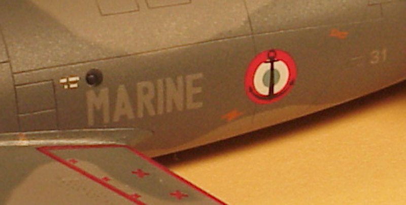
| This close-up shows how nice the Carpena decals worked. The black dot above the 'M' shows that the Future softened the decal enough to pull it down into the circular engraving (which I clearly did not expect). But the French roundel did not soften sufficiently, it did not pull into the panel line below. Perhaps this was caused by the multiple layers of ink on this specific decal.
| 
|
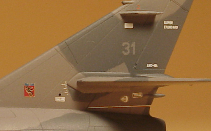
| Promised earlier, some words about the masking around the horizontal tail roots. The Super Etendard has an adjustable tail. It seems that they are painted with the tail in an extreme attitude, nose down. This results in strange color demarcations. I don't understand why the forward/lower part is in the dark color, and the rear/upper part in the light color, but that is what my slides showed. On the right side, both areas are in the dark color.
|
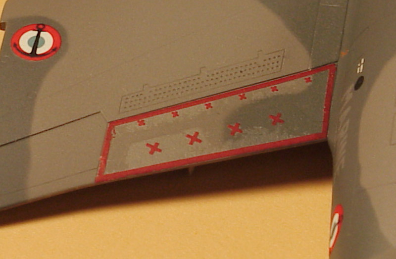
| Not everything went perfectly though. The flap decals did not fit the Italeri model at all. I guess they were designed for the Heller model. Tthe only other decals that suffered that problem too were those for the blow-in doors on the intakes. I decided to cut up the flap decal in four parts. I started with the leading edge part, the part with the small crosses. It was quite a lot too long, and two crosses had to go. The same applied to the trailing edge part. From the remains of the decal I cut out two pieces to make the inboard and outboard stripes. Because the above was already difficult enough, I skipped making a cut-out on the inboard forward corner of the flap decal. All looked well, until I sprayed a clear coat over it. Shitzu! Major silvering! Some delicate painting is in order to restore this problem.
| 
|
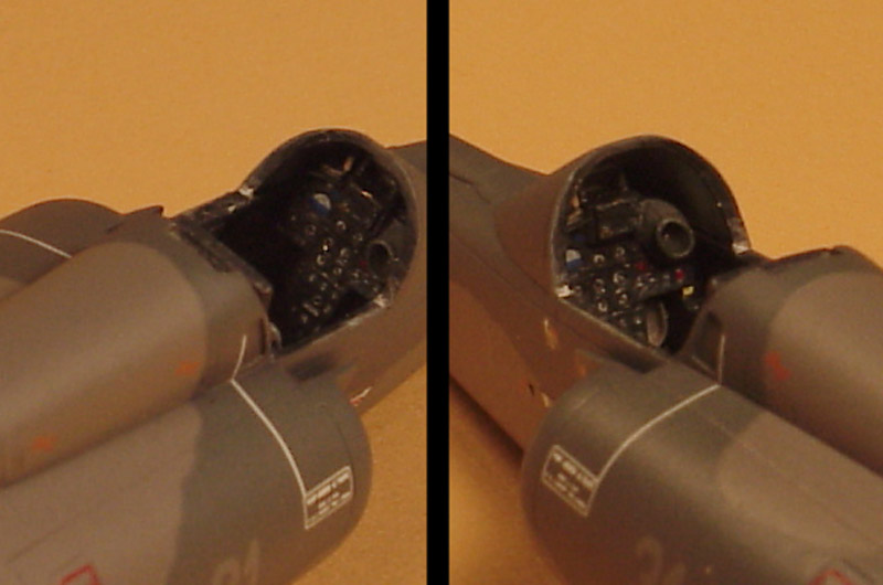
| I popped off the canopy, and now I can finally show my 'black' painted cockpit. Because of the masking on the windshield, the coaming detailing (such as the HUD/gunsight) cannot be seen now. One of the rudder pedals, stolen from an Me 163B photo-etch sheet, can be seen too.
I bought a Neomega Martin-Baker Mk4 seat, but it didn't resemble the Super Etendard's seat at all. I learned later that there are no fewer than 82 subtypes, all of which differ in some or large small way. Eventually I found a HiTech (France) resin Mark 4A seat (stock number 72504), specifically for the Mirage III, Etendard and Super Etendard. As far as I can see, it is completely accurate for a Super Etendard. I modified it slightly: I added hip belts (which were absent) and draped over the side consoles, and I removed the molded shoulder belts, and draped them over the top of the seat. The bottom and the back of the seat were sanded slightly to make it fit in the cockpit. The seat is rather narrow, and looking back I could have used slightly wider side consoles. The stick was robbed from an Academy Messerschmitt Me 163, which has a surprisingly modern looking stick. Its pedestal was cut off to make it fit.
|
Details
| The aluminium replacement speed brakes shown earlier were fitted with plastic card arms and some interior detailing. A paint coat blended everything, and another important detail was declared finished.
| 
|
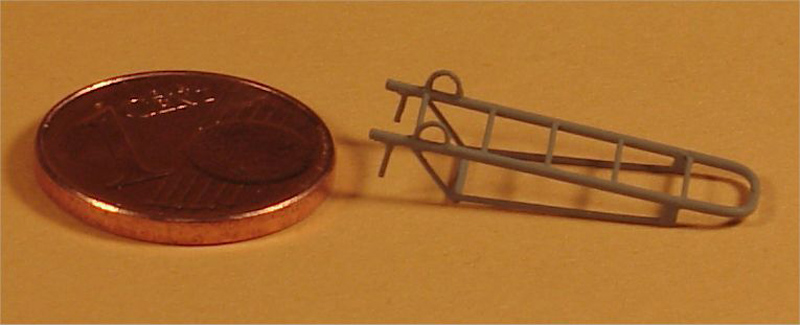
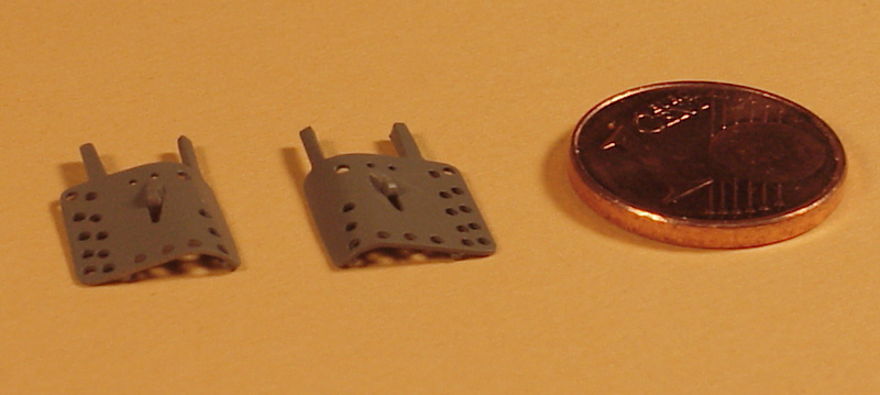
| More small stuff. I wanted to pose my Super Etendard parked, and this required a boarding ladder. I made a drawing based on various photographs, scaled it down to the appropriate size, and built the ladder from 0.5 mm brass wire and 0.3 mm plastic rod, using CA glue throughout. The assembly took place on top of the small drawing, building it free-hand would be impossible. The 1 eurocent coin gives an idea of its small size. After a coat of paint it looked even nicer than I expected. In 2007, L'Arsenal came out with a photo-etched Super Etendard ladder.
|
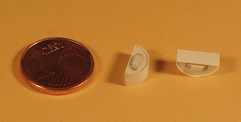
A parked Super Etendard has its intakes plugged. More scratch building required! I started with a piece of 1 mm plastic card, that I cut to fit the intake loosely. Next an oversize piece of 0.1 mm plastic card was glued around the outboard curved side, and it was test-fitted again. After some sanding, it had enough play to allow the addition of the inboard straight piece of 0.1 mm card. I decided not to cut away the excess 0.1 mm card on the rear side; it ensures a straight alignment of the covers. Lastly a small block of plastic was glued on.
The intake plugs are not ready yet. A small handgrip is absent, and there is another tiny plug between the splitter plate and the fuselage side, and some steel tubes that connect the two. These are so small and delicate that I could only assemble it on the model, after it was finished and fixed to its display base.
| 
|
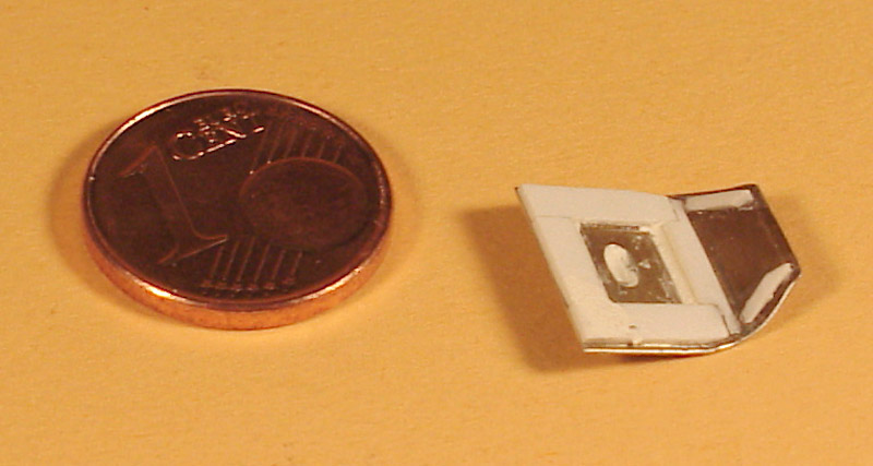
| Inspired by the success of the speedbrakes, I decided to build the main landing door from scratch too. I used 0.2 mm aircraft grade aluminium, rounded one edge, and added some bits of plastic to build the interior structure. Only when the model was finished I noticed how little of all this effort could be seen.
|
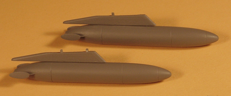
| The pylon tanks and pylons were improved slightly. 0.5 mm steel pins were glued in the pylons, and matching holes were drilled in the tanks. It was then possible to fill the notch in the top of the tanks with Milliput, and the corresponding ridge on the pylon was cut off. All fins were sanded thinner and sharper. After painting I concluded that the tanks were ready for installation.
| 
|
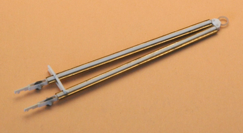
| Although I planned it thoroughly, the scene wasn't properly balanced, and I needed something to fill the empty space to the plane's left. An Exocet seemed a good idea, but I couldn't find a photo of the dolly on which it is transported on the flight deck. Second best was a tow bar. Photo references weren't too clear, and it appeared there were different versions.
I decided to build the most complicated one that had square tubes with 'T' stiffeners added to the sides. It took me a looong time to find suitable materials: brass I-beam of 1 x 0.6 mm! Even better, it had a manufacturing defect, creating one very thin and one thick flange. I glued the thick flanges together, then added 0.8 mm wide plastic strips on top of the glued flanges. The result was a square tube with T-flanges.
|
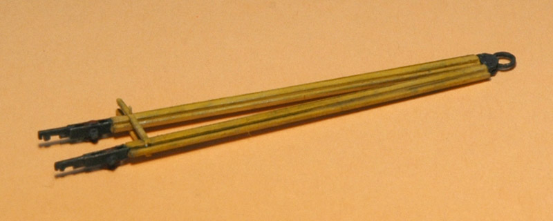
| The aircraft couplings were built from strip with some cut-outs, and two pieces of strip sandwiching a small wheel cut from plastic tube. Grandt Line bolts were used to simulate the axle. On the other end I had to guess the details, lacking photos. I used a towing ring and some pieces of card to create something likely. Last detail was a spreader strip on both the upper and lower sides, detailed with a pin and a clamping piece. The assembly was painted yellow and black.
| 
|
Weathering
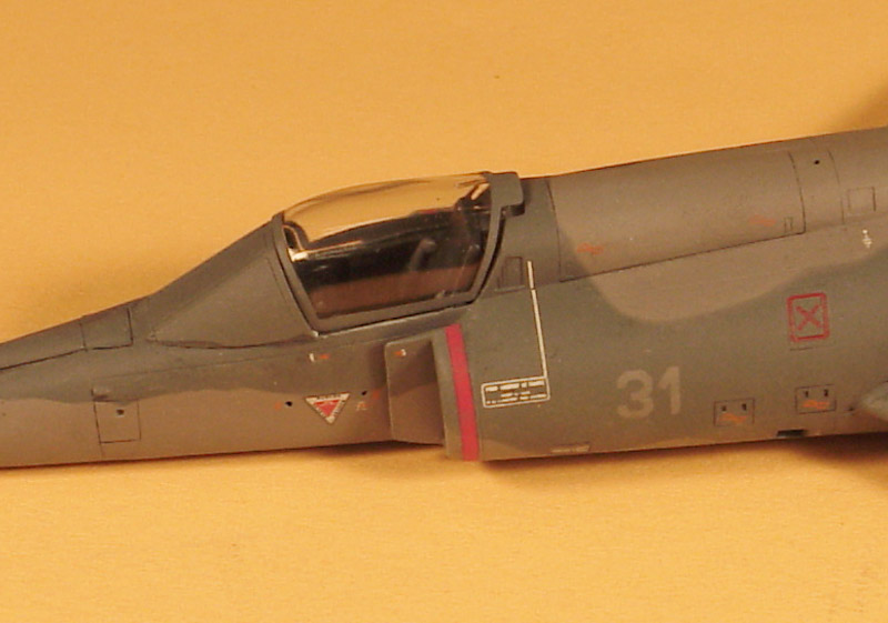
| I mainly used gouache water colors to apply a light weathering on the model. I like that you can remove all of it if you don't like the result. I applied a light wash in the panel lines, and a slighter stronger one to the hatch on the spine behind the canopy.
| 
|
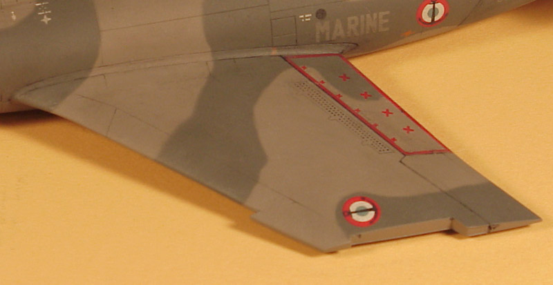
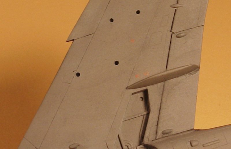
| The wings were weathered in the same way. I also applied very light weathering with enamel paints, creating very slight color differences. It is hard to see, but it created a bit of 'anti-monochromatic' finish. Interestingly it also reduces the contract between the camouflage colors.
|
| The lower sides of the wings were weathered a bit more heavily. Or maybe it's more apparent because of the single color on the lower side.
| 
|
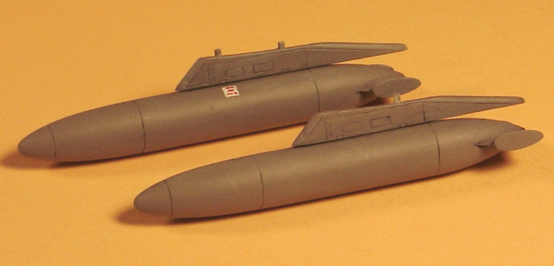
| The pylon tanks also came alive by a bit of weathering.
|
Carrier deck
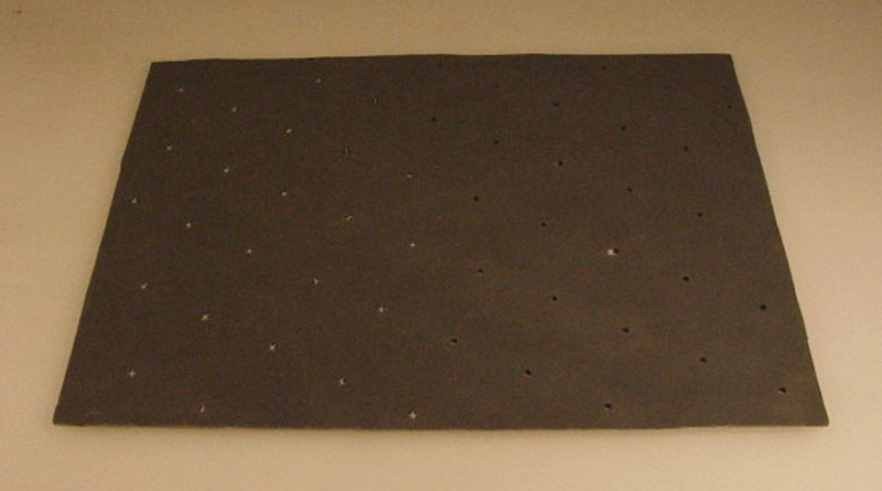
I planned to use a standard photo frame as the basis for my model. They are only available in a few standard sizes, but a 15x21 cm frame fitted my Super Etendard nicely. I took a piece of aluminium sheet as the basis of my carrier deck. To recreate the rough anti-skid coating, I used sand paper. I had no idea what grade I should use. I bought all grades between 300 and 1200, and spray-painted them to take away the metallic glint. I then used a 1/72 figure to judge the effect. To my surprise, a fairly rough grade, 400, was the best one.
To make things complicated one more time, I decided against gluing the sand paper straight on the aluminium. I had seen something like it before, and it was just too flat and featureless. Also, when I visited an American aircraft carrier, I noted that the deck plates showed some waviness. (Note: I asked on rec.models.scale whether this was a correct observation, but no-one agreed, including former US Navy personnel). I measured the frame pitch of French carriers from some photos found on the internet, and concluded it was around 2.5 meters, translating to 35 mm in 1/72 scale. I glued three layers of paper strips on the aluminium, and on top of that the sand paper. The results is fairly subtle, the waves are only 0.3 mm, just like I wanted them. The photo shows the effect partially.
| 
|
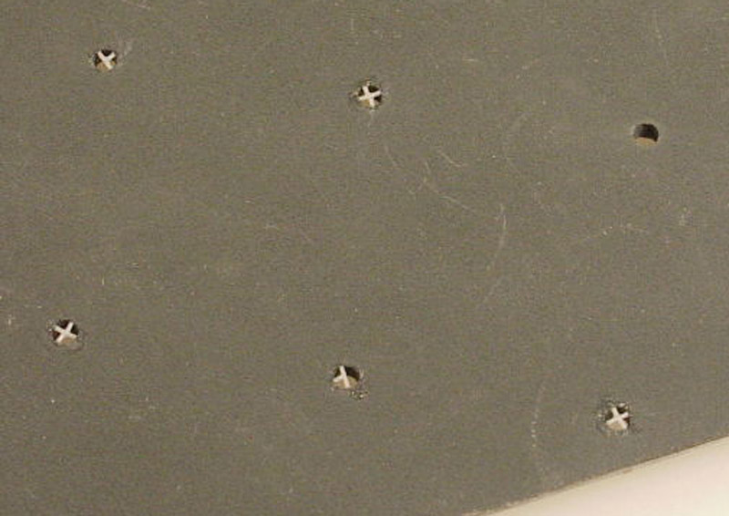
| Then the pad-eyes. It was a major problem to establish their pattern. Finally I found a photo where they showed reasonably clear, and I concluded their pitch was about 1.65 meters, or 23 mm in 1/72. I quickly drilled the holes in the base plate. Only then I noted how 'busy' it now looked, way more busy than photos suggested. Perhaps my pitch figure was wrong? Anyway, I decided to proceed.
From measurements I concluded that the French pad-eyes were some 150 mm diameter, or 2 mm in 1/72. That appears to be quite some smaller than pad-eyes on US Navy carriers. It also meant that I could not use available photo-etch tie down crosses. A horrible job dawned.. I stretched sprue to a suitable diameter, and cut pieces of 2.0 and 0.8 mm. The longer pieces were reasonably easy to glue in the drilled holes, but the small ones drove me crazy. Only 50 pad-eyes to do.. The photo shows pad-eyes in several stages. Black paper was added to the bottom side to close the pad-eyes.
I did not add the tie-downs, between the pad-eyes and the aircraft, since I had no way to portray these tie-downs realistically, and partly because I had insuffient information on their installation. But maybe I will add them one day, when suitable materials become available.
|
Matra 155 rocket pods
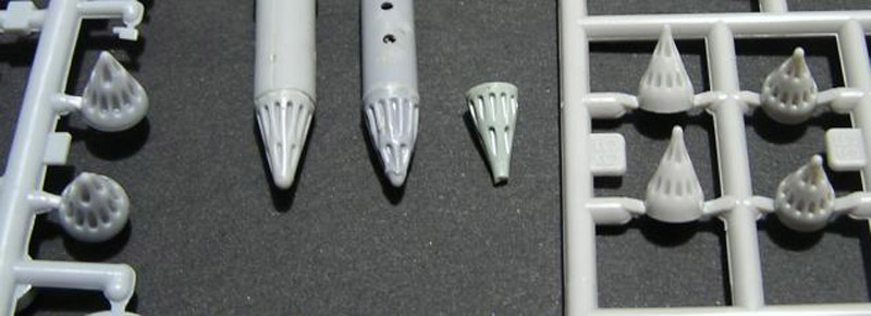
| I wanted to fit my Super Etendard with simple old-fashioned Matra 155 SNEB rocket pods. I guess I want to compensate for the high-tech Exocet image somehow. The pod is also referred to as Matra LR-155, and the F4 pod is externally identical but is only for helicopters. I also found that the 155 is a reusable 18-shot pod, and the 115 is a disposable 19-shot pod.
There are plenty of Matra 155 rocket pods to be found in various kits, but finding a correct Matra 155 rocket pod is another thing. The photo (courtesy of Rob van Riel) shows from left to right: Italeri USA/NATO Aircraft Arms, Matchbox (possibly Phantom), Airfix (unknown kit), Hasegawa (possibly old Harrier GR1/3) and lastly Fujimi UK Phantom. The diameter of the Matra 155 pod is 410 mm, translating into 5.7 mm in 1/72 scale. The Italeri pod is 6.9 mm (or 21% too large), Matchbox 6.1 mm, Airfix ? mm, Hasegawa ? mm, Fujimi 6.0 mm. Most have rather vaguely defined rocket tubes, except Hasegawa. They all lack the very closely spaced rocket tubes of the real thing.
|
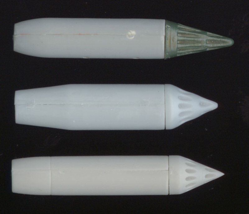
| From the above, I selected the Matchbox (top), Italeri (middle) and Fujimi (bottom) rocket pods for a comparison. The Italeri pod looks way too fat. The Fujimi nose cone was sanded to remove the peculiar tip, but the nose cone does appear rather blunt to me, but I don't have data to support this. The rocket tubes of the Matchbox are quite unrealistic, so the Fujimi pods appear to be the best compromise. The bodies of the Fujimi pods are not round by the way, I had to sand the gluing faces to make them circular.
| 
|
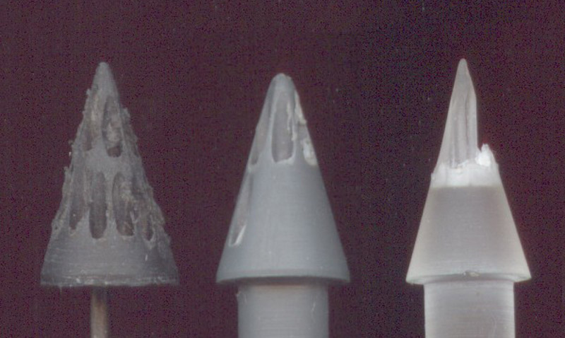
| Two machinists also tried to make a nose cone, but failed. The one on the left was CNC-drilled first and then turned, but the holes were not positioned accurately, and the cone shape emphasised this clearly. Also, the material used was clearly not the best suited. The middle attempt was turned first, and then machined with a 1 mm bit. Accuracy was still not perfect, but possibly acceptable. The flash was impossible to cut off cleanly, so I cast epoxy resin copies of the cone shape, hoping that a more brittle material would work better. The horrible result can be seen on the right. This ended the machinist's attempts..
|
| Rob van Riel finally found a reasonable solution to the problem. Aeroteam (and later ICM) issued a 'Modern Soviet Aircraft Armament Set' that contains a rather inaccurate B8 rocket pod (the B8 in the Dragon set appears to be much better dimensionally). It has 13 rocket tubes in the outer ring (with one opening) and 7 in the inner ring, and fits the Fujimi body. I cut open one extra tube, making a total of 21 instead of 18 of the Matra pod. It's not a perfect solution, but the best I could do at the time. The tip of the nose cone needed some sanding. The body was shortened 1.5 mm at the front end, and opened at the rear end. I also scribed a panel line just behind the forward end of the body, and then glued the nose cone on. The transition between the parts was filled and sanded to make something of a curved smooth transition there. The recess in the body was filled with a piece of strip, and two short steel pins were glued in to fit them to the pylons. I still have to paint the pods, but I haven't found out whether the bodies were bare metal or painted silver. I also found a photo that shows a reinforcing plate fitted to the top of the pod, possibly a reinforcement for the sway braces (if used). I will probably add that.
| 
|
PS #1: I found a reference to a PP Aeroparts 'Pin Point' series from 1991, which included 'Matra pods' as catalog number 1, in both 1/72 and 1/48 scales. Possibly also AC730. To be confirmed.
PS #2: The Aviation Workshop, under the brand name 'Model Alliance', issued resin 'SNEB 68mm Rocket Pods' with catalog number CS119 in March 2008. I briefly looked at them inside the bag, and they looked pretty good to me, but I could not compare them to other models of the Matra rocket pod.
PS #3: in 2007 I found out that the Supermodel MB 326 and 339 models contain near-perfect Matra rocket pods. A year later I finally found a pair. Photos to follow. Italeri reissued these kits in 2011 and 2010 respectively.
PS #4: in 2010 Model Art issued 1/72 scale 'Matra LR150 rocket pods for Etendard IV and Super Etendard' with catalog code 'maccess 18'. I checked them out briefly, and they looked excellent to my eye, especially the 18 rocket tubes are well formed. They come with pylons. Curiously, the 'exhaust shield' at the rear shows some shrinkage, that suggests an injected plastic origin.
PS #5: in 2010 Airfix reissued its 1/72 Buccaneer model (#4049), and added two sprues with stores, one of which contains four Matra 155 pods. A sprue picture on Cybermodeler shows reasonably shaped pods, but the tubes are rather small in diameter.
PS #6: in 2016 CMK issued a set of two 1/72 resin Matra 155 pods, catalog number CM7340.
The finished model
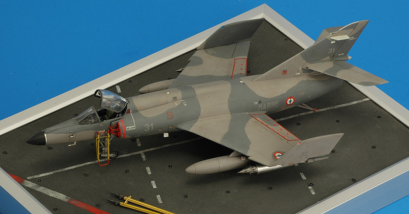
| I glued M1.4 nuts in the wheels, drilled holes in the carrier deck, and fixed the M1.4 screws from below. Having the model fixed rigidly to the base makes life much easier while adding the final details. I will definitely do that again with my next model.
|
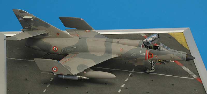
| The deck was painted to represent the parking space between the end of the angled runway and the superstructure, just behind the front deck lift. The yellow area marks the edge of the runway, and the solid and dashed lines white lines are parking alignment stripes I believe. The red-white line could a 'foul line' like on US carriers.
| 
|
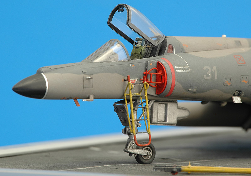
| The close-up of the nose section shows the ladder (painted in squadron colors) and the two-part intake plug. The front tire was flattened slightly, and a small hatch was opened that is usually open while on the ground. I also added some detailing to the canopy: a rear view mirror, hooks/pins on the sides, and an inflateble seal.
|
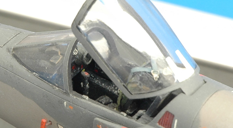
| In this photo you can see something of the cockpit detailing. There's the stick, the instrument panel and the side console, and the parachute risers / shoulder belts draped over the top of the seat, as is done on the real thing. The ejection handles of the seat were painted black-yellow, and looked lovely, but strangely they are missing now!
| 
|
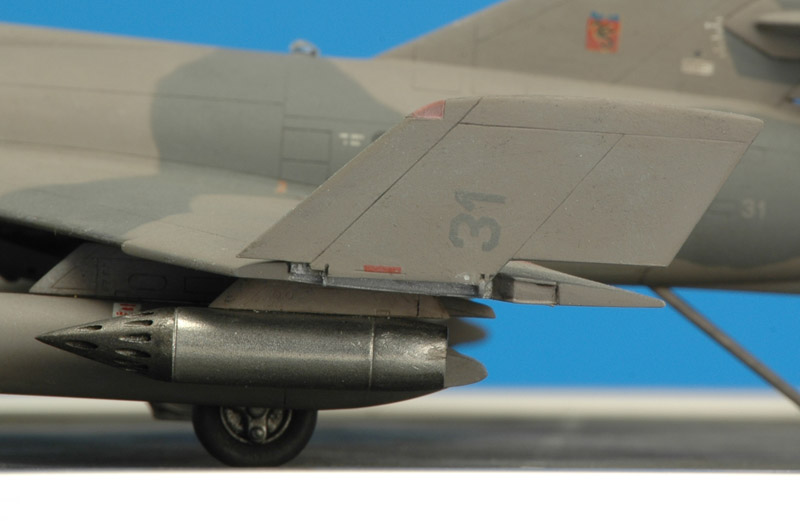
| A close-up of the wing hinge shows its simplicity: there is not much more than two hinges. The edges of the ailerons were detailed with stretched sprue to simulate the sheet metal edges.
|
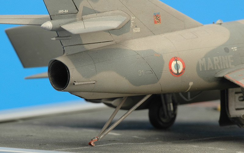
| The rear fuselage shows the lowered hook and the drilled out fuel dump. The scratch-built main landing gear centerline doors can be seen under the fuselage.
| 
|
2021 upgrade
I'm a member of IPMS-The Netherlands regio Zuid-Holland, and for a club project I want to upgrade the model with a few figures.
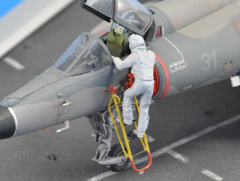
I wanted the pilot climbing the boarding ladder. Inspiration is a photo from 'World Super Carriers', page 81. I bought PJ Productions set 721125 'Set of two F16/F18 pilots standing/boarding'. The boarding pilot had a bit of mould shift, so first I had to apply some Apoxie putty to get rid of the step on the legs. My scratch-built boarding ladder had come loose over the years, and I reattached it at a 20 degree angle.
Next I bent the left leg a bit more, so both feet would be on the ladder steps. This was done by cutting a small V-groove near the pelvis, and regluing the leg. Then the arms were added, with the left one holding on the the canopy sill, and the right one holding on the intake's splitter plate. This is the status of the photo, with Mr Surfacer (spray can) covering all the crimes.
| 
|
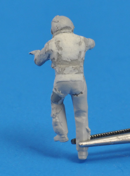
| Next step was some research of the flight gear of the pilot. The PJ Productions figure appears to wear a parachute harness, which made sense for a Martin-Baker ejection seat. But more study of Super Etendard photos revealed that the harness was left on the seat. And that's what I had modeled 20 years ago, see the previous photo - the harness is resting against the seat back. Therefore the pilot would board with only a G-suit and floatation collar.
I decided to modify the figure's back a bit: I scribed a line to outline the top of the G-suit 'belt', and added some Apoxie to exted it downward a bit. The remains of the harness on the top half of the torso were removed with a knife, the gaps filled with Apoxie. I will need to add some wrinkles there later.
|
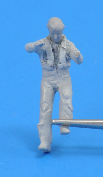
| The pilot figure got a new head, cut from Hasegawa's 'US pilot / Ground Crew Set' part B15. Also I built up the life jacket a bit with Apoxie. Unfortunately the left hand was lost at some point.
| 
|
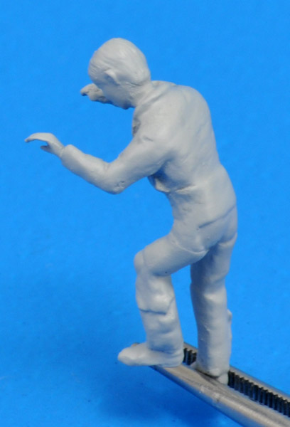
| I added a new hand, but decided to replace the hand with the lower arm, to avoid having a glue joint at the smallest cross section. The hand was rotated compared to before, now holding on to the canopy bow. The pilot's back was the last thing I worked on, trying to add some wrinkles, but I found out that's not easy.
The flight suit itself was darkish green, the G-suit and floatation collar both slightly lighter and more yellow.
|
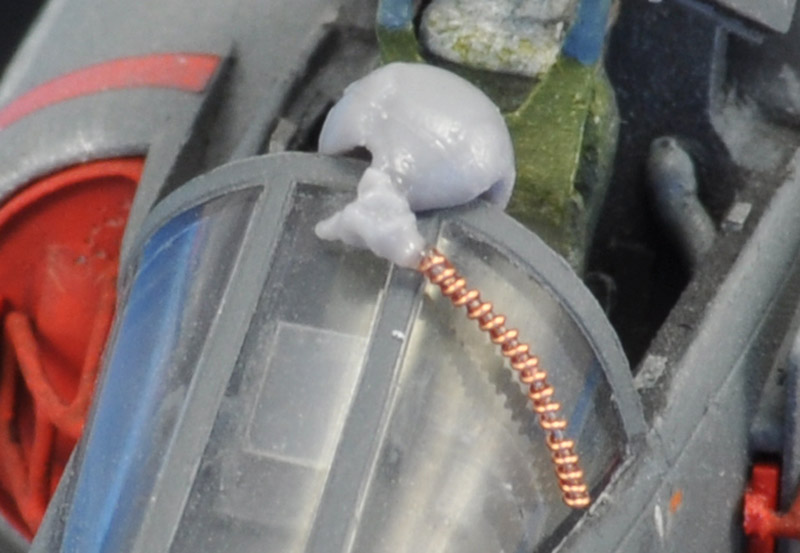
| I wanted to pose the helmet on the canopy bow. Luckily, Hasegawa's 'US pilot / Ground Crew Set' includes a separate helmet (part B12) and oxygen mask (part B11). I built my own oxygen hose from
0.1 copper wire wrapped around 0.2 mm steel wire, and then combined all the parts. The result was very, very vulnerable but also very sweet.
|
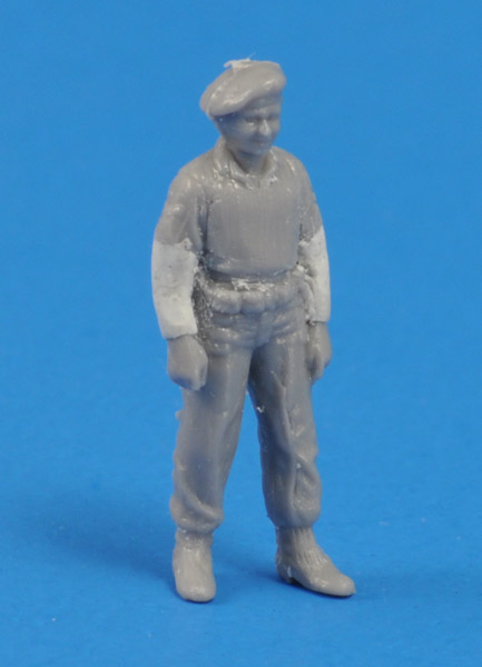
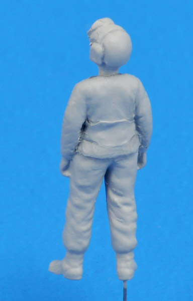
| For the crew chief figure, I wanted a figure in a relaxed pose, waiting by the ladder until the pilot is seated. I looked through Fujimi's 'Deck crew set + fire truck' and 'Deck crew set + MD-3', but these sets did not contain a figure that looked suitable. Instead I decided to use an 'air policeman' from Hasegawa's 'US pilot / Ground Crew Set'. Part C12 looked like it had potential, but it would require considerable modifications: a long-sleeved jersey, a wide leather belt, and another head. I started with removing the breast pockets and added Apoxie to make long sleeves.
| 
|
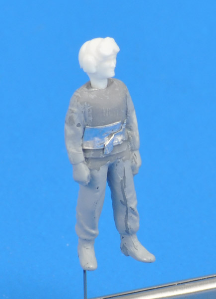
| Fujimi's 'Deck crew set + fire truck' part A15 donated its head for the crew chief. He looks up slightly, to the pilot on the ladder, which makes the whole scene much more natural. I did a little delicate carving to visually separate the goggles from the cranial, and then outlined the cranial segments themselves. Next I drilled an 0.3 mm hole in one leg and installed an 0.3 mm steel wire. A corresponding hole in the deck makes the figure fixed to the deck.
|
I reworked the belt, reducing the height on the front side, and changing the shape on the rear side. Furthermore some more mould lines were removed.
I *think* a crew chief wore a brown yersey and dark gray/blue trousers, with a very wide leather belt. The headgear (or complete head) will probably be sourced from one of the Fujimi kits.
| 
|
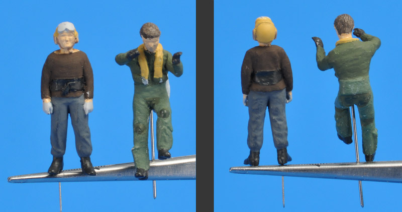
| Here are the two figures about halfway the painting process.
|
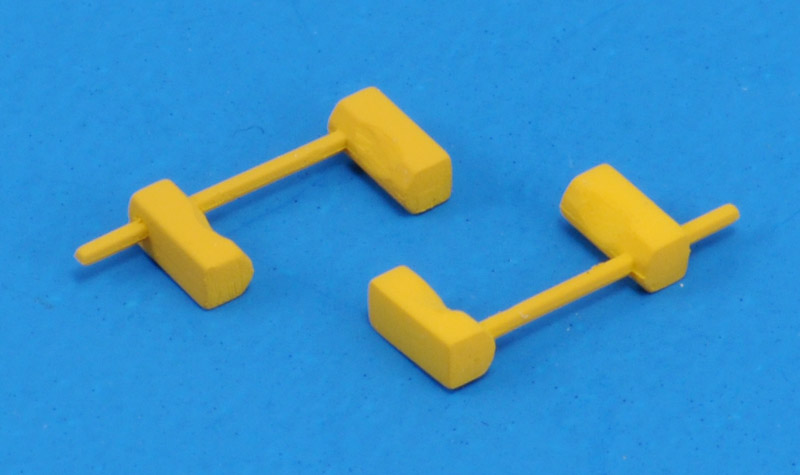
| Another small update: wheel chocks, that make sense for an aircraft ready to start its engine. Photos showed that the type of chocks in Fujimi's 'Deck crew set + fire truck' (part E3) were correct for the French Navy. The fit around the tire was too tight however, but that could be solved by sanded 'tire dents' in the blocks. The real thing had these too. The blocks were painted Humbrol 24, the bar would be painted metallic black later.
| 
|
References
References for this aircraft are pretty rare and difficult to find. I've identified the following, of which I own the first one:
'AMD Etendard - Super Etendard' by Alain Pelletier, Ouest France, 1982. 32 pages, A5 size, French text, black and white photos with color photos on the cover, some detail photos, Etendard IV drawings.
'Super Etendard' (Super Profile series), Christopher Chant, Haynes, 1983. English language, 56 pages, about A4 size. After years of looking I found this reference recently, but a quick check revealed that it wasn't very useful for modeling purposes. It contains black and white photos only of fairly low contrast, and no detail shots.
'Dassault Etendard IV & Super Etendard' (Monographic 1), Alain Crosnier and Jean-Michel Guhl, SupAir Publications, 1988 I think, French language. Never seen it in the flesh.
an Argentinean booklet (A5 size) on the Super Etendard also exists. It looked like part of a series about aircraft used by the Argentinean armed forces.
KPM Kaznejov walkaround of Super Etendard number 25, excellent!
French Air Wings walkaround
Aftermarket accessories
Here's an overview of accessories available for the Super Etendard in 1/72:
Airwaves photo-etched detail set (7)2091, apparently out of production, never seen it
Eduard photo-etched detail set (number to be added), issued in 2001. I have seen it, and it looked pretty good to me
HiTech resin Mark 4A seat, number 72504, for Mirage III, Etendard and Super Etendard. It looks very much like a Super Etendard seat to my eye
Carpena, now Colorado, has a decal sheet DCA7256 for Etendard and Super Etendard. Simply a fantastic sheet. However, the instructions are not very complete, and many decals are not numbered or pointed out. It took me a lot of research to find the correct placing. Write me if you have this sheet too, since I made a better decal placement guide
In 2007, ExtraTech issued a photo-etched detail set (72160) for the Heller/Airfix model. The IPMS Germany site has a review. The set appears to contain very useable parts.
Late 2009 / early 2010, Model Art issued decal sheet MA7260 for French Super Etendards (current camouflage only) and FAA Sea Hawks. The sheet appears to be very complete, with a lot of stencils and a complete decal placement guide.
Thanks
I want to thank the following people, who kindly provided reference material for my Super Etendard model:
Pierre-Henri Baras, co-webmaster of the French Fleet Air Arm web site
Sandro Tomasetto from Brazil, for his scans of a Super Etendard article
Modeling links
Concluding this page, some links to other Italeri/Academy Super Etendards:
Return to models page


