3D printed parts for the Monogram 1/48 F-84F
| For my F-84F stores configuration model I wanted a fully detailed ATO rack. It was based on very limited reference material. |
| For my F-84F stores configuration model I wanted a fully detailed ATO rack. It was based on very limited reference material. |
| Monogram provides a set of four bottles, but forgot the rack that these bottles mount to. Using the very few reasonable photos that I could find, I laboriously made the drawing shown here. I guess it's +/-10 percent correct, and I still hope to find a real ATO rack one day to confirm that. The drawing is unfinished, and will stay that way, because I will convert it into a 3D model. | 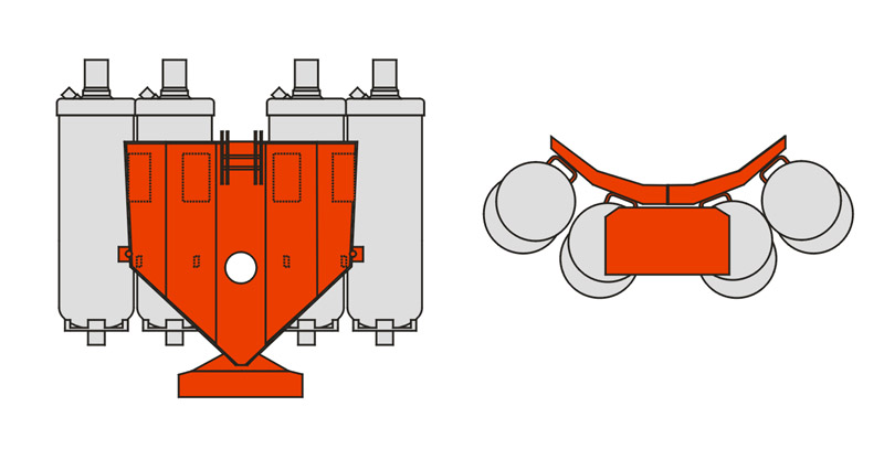
|
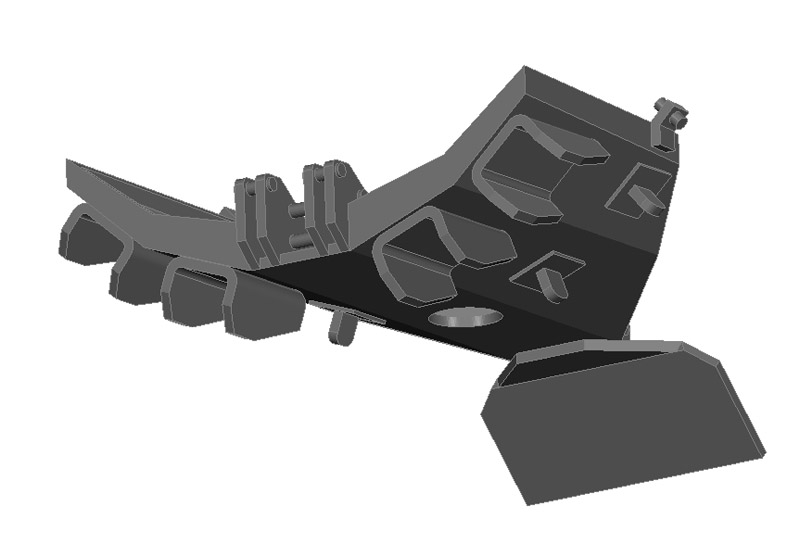
| Here's the first CAD model of the ATO rack. Wall thicknesses are scaled for 3D printing: 0.3 mm. This will be a difficult part to cast in resin, with all the protrusions. |
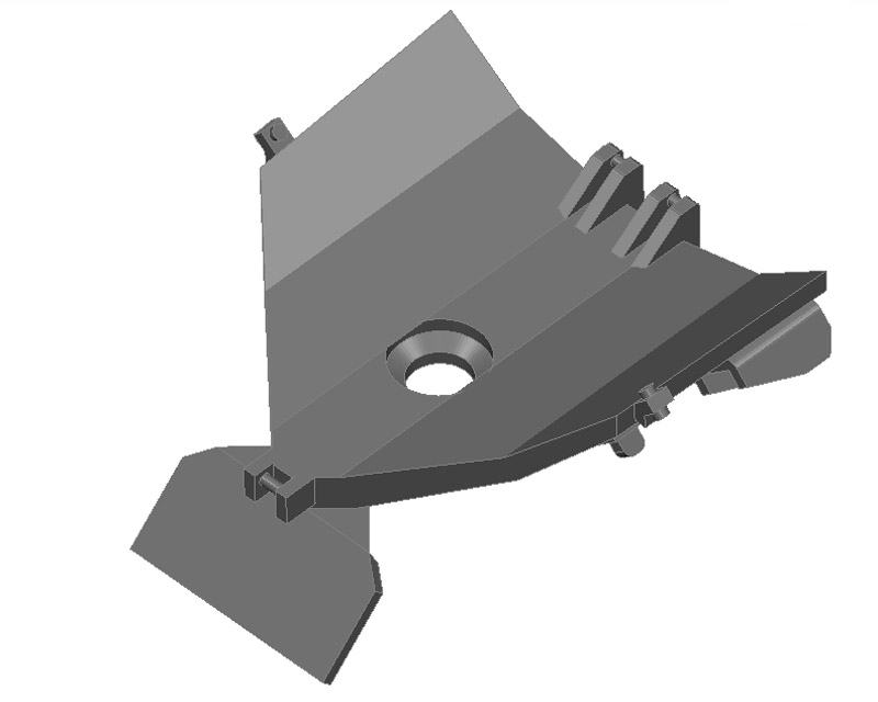
| Top view of the same first CAD model, showing the three attachment points on the F-84F's three hooks. | 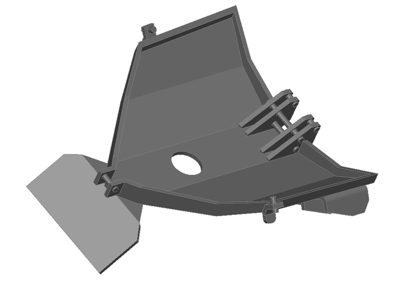
|
| Here's the first 3D print of the ATO rack. The 'spoiler' at the front (top here) was not printed properly. Freeing the part from the numerous supports is not going to be fun. |
| Here's a first test-fit on the F-84F. The part fits very 'naturally'. But I haven't established the exact position yet. | 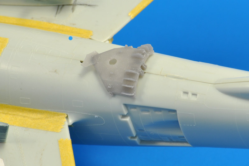
|
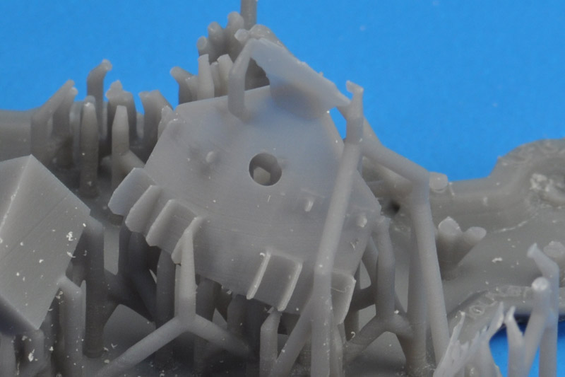
| The fifth print finally yielded a perfect ATO rack. But you also see how it's hidden in a forest of supports. This makes it near impossible to get to the attachment points of the supports with (for example) a JLC saw. |
| The parts had no less than five cracks and breaks before it was free. This is partly due to brittle nature of the 3D printing resin, and partly due to my delicate CAD design. Back to the drawing board. | 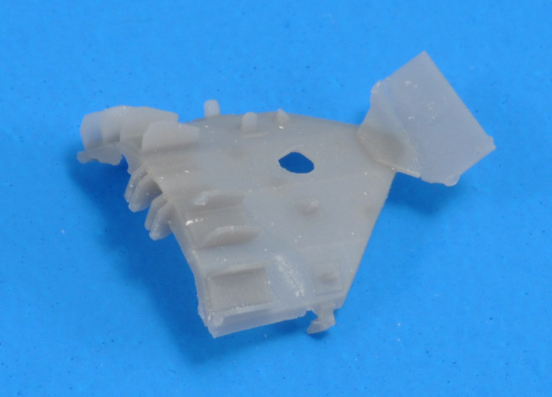
|
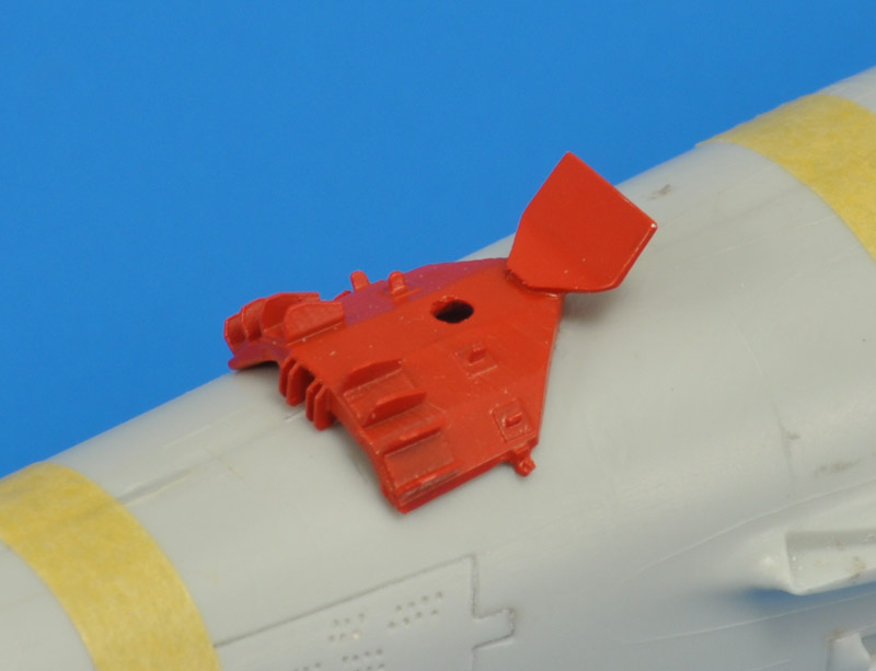
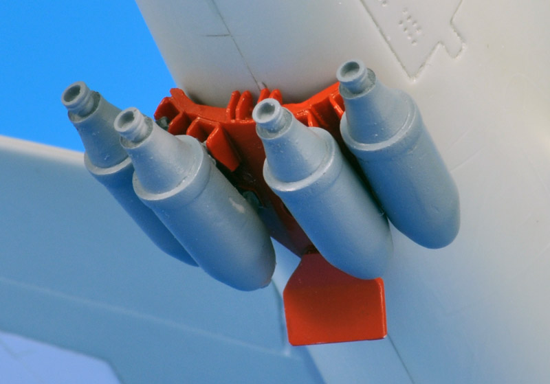
| I decided to make the above part usable for the interviews. Before I could use the part, the spoiler had broken off. I made a fast replacement using 0.3 mm aluminium.
First were the magnets. There was room for a 2x2 mm magnet near the rear attachment brackets (left in the photo), and I used a cluster of three 1x1 mm magnets near the front bracket (right in the photo). Then the rack's interior was filled was filled with Apoxie to give the part a lot more strength and stiffness. The rack was painted MRP-184 Signal Red. Following photos, I found the exact position of the ATO rack on the lower fuselage: the set screws on the side of the ATO rack rest on the frame line just ahead of the speed brakes. This in turn determined the position of the 2x2 mm magnets in the lower fuselage. |
| Here's the redesigned part, with the main rack part made solid, and the 0.3 mm parts made 0.45 mm. Hopefully this will work better for printing. | 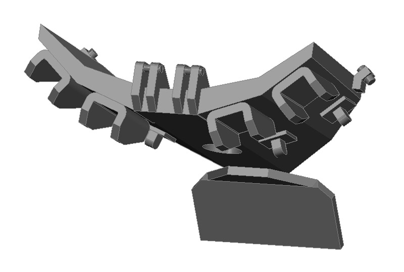
|
| I made an extra hole on the inside to make the original hole still like a sheet metal hole. I have some doubts whether the 'spoiler' is worth printing, or better made from plastic card, but the next printing round will tell. |
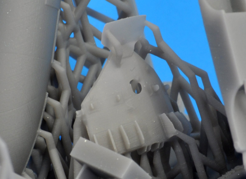
| And here's the second printed part, without any broken parts, and with the aerodynamic plate still attached. Unfortunately the rear corners (right in the photo) are rotated compared to the rest of the part. | 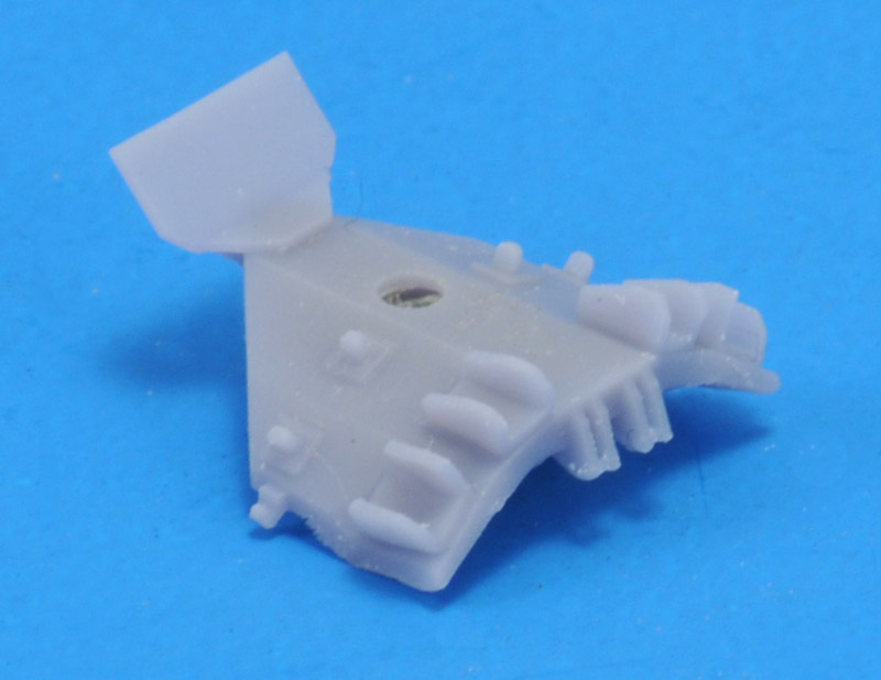
|
| The inside view should show a five flat surfaces, but the whole front end (top of photo) is unfortunately deformed.
Much later I learned why the corners were printed deformed: they were not sufficiently supported during the early stages of the printing. |
| My skills and understanding slowly improved. I also learned how to add the supports manually. This helped in two ways: I could optimize the supports so they would not disturb the 'good' side of the part, and secondly it allowed me to avoid the bent corners as experienced earlier. Here's how I added the supports, in 'front' view.
This is a difficult object to make a good mould of, due to its shape and the way it should be pulled out off the mould. The printed part incorporated the 'gate' parts I would normally add manually from plastic strip and card, to make the part castable. It was an experiment and a first for me, to add the gate parts in CAD. | 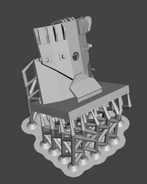
|
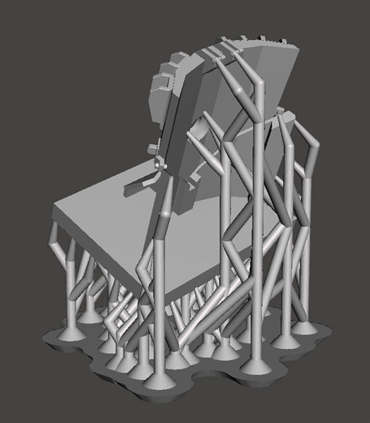
| And here's the 'rear' view of the supported part. Added the supports myself also saves work for the person doing the actual printing. My STL-files include the supports, so the parts can be printed straight away. |
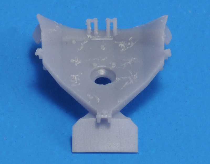
| Here's the printed part, cleaned up with all supports removed. A few thin layers of Tamiya Fine Surface Primer were added, sanded in between, to removed the slight striations. | 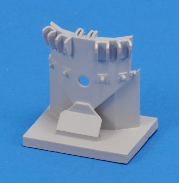
|
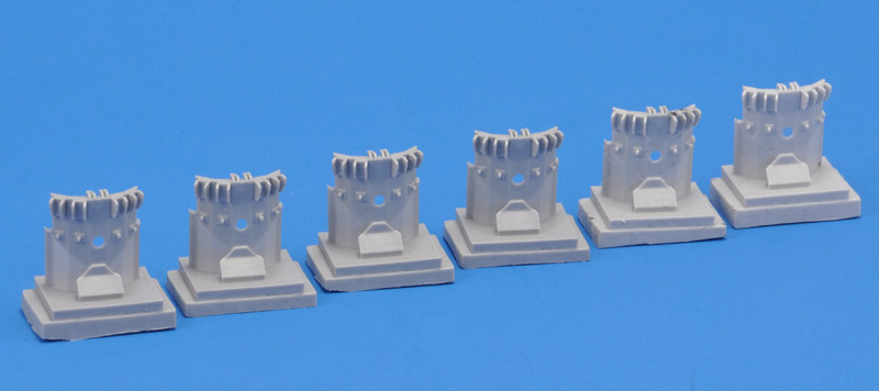
| The ATO rack is now in production, and shown here are the first six castings. If interested, see the For sale or trade & wanted page for more information. |