High Planes 1/72 Bearcat Racer


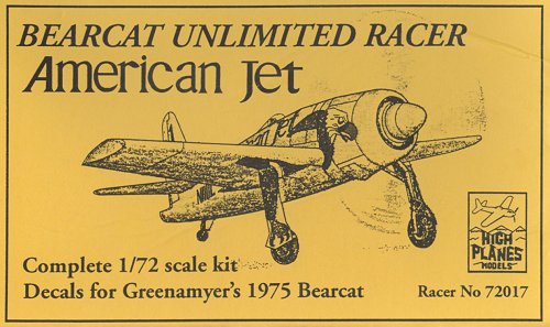
I have no special interest in racer aircraft, but for some undetermined reason I always liked the yellow Bearcat flown by Darryl Greenamyer in 1975. I knew that High Plans from Australia was working on a limited run model of it, and I bought it soon after it was released in late 2000 or early 2001 (kit number 72017). I haven't progressed very far with the model yet.


The kit

From reports on rec.models.scale I knew roughly what to expect from High Planes: a nice and accurate model, but with quite some flash to carve away. This turned out to be true for the Bearcat too: once cleaned up, the parts generally show excellent detail. One exception is the spinner. The main gear legs are nice white metal castings, and the minute canopy is vacformed. The decals are printed by the Fantasy Shop and look excellent. That said, the kit doesn't fall together, it is a short-run model, and some 'real' modeling is required. For example, the construction method of the fuselage (sliding over the single-piece wing) is quite strange and feels very old-fashioned. I did not check the dimensions of the model, but I am confident that they are accurate.


Construction

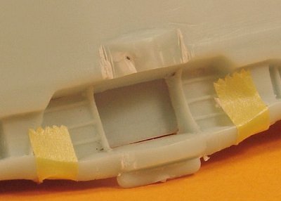
I started with the wing to get a feel for the model. It is a simple two part construction. First snag was that the cockpit floor forms the 'roof' of the center of landing gear bay, and this did not fit. Instead of laborious scraping, sanding and fitting, I opted for a radical solution. I made saw cuts parallel to the cockpit floor. This removed the offending plastic, and the problem solved. Some thinning of the wheel wells was required to make the wing halves fit nicely.

Before gluing the halves together I thinned the trailing edges considerably. I noted that the wing halves could not be lined up simultaneously at the leading and trailing edges. I chose to line up the trailing edge, since the leading edges would be much easier to restore. I then glued the parts with super glue. I still have to clean up the leading edges, give the wing tips their concave surface, and close the inlets in the leading edge.
Over to the fuselage. First job here was to cut out the wing openings, which are molded closed. When I test-fitted the fuselage halves over the (single piece) wing, the fit was really bad. The openings were too small, so the fuselage halves couldn't touch, and they did not line up in pitch direction at all. I enlarged the left wing opening downwards, and the right one in both directions. I also had to decrease the size of the 'bump' on the wing behind the wheel wells (visible in the photo above) to allow the fuselage halves to touch each other. After two hours of cutting and fitting it started to look better.
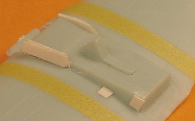
The ordeal wasn't over yet. The fit of the fuselage halves around the wing was rather loose. It was quite possible to create zero dihedral on one wing, and way too much on the other. Also, it would be very easy to create unequal length wings by shifting the fuselage sideways! I decided to pack the cockpit floor to create a clearly defined fuselage position. I carefully put some pieces of tape on the wing to serve as reference lines. Because the fuselage halves appear to be of different thicknesses, I had to carve away some plastic at the right rear corner of the cockpit floor, add a thin spacer at the right front, a four times thicker one at the left front, and a thin one at the left rear. I also added a small spacer on the wing surface, because the left wing opening had become too large. The cockpit floor will need some cleaning up after this rough job, but that's for later.
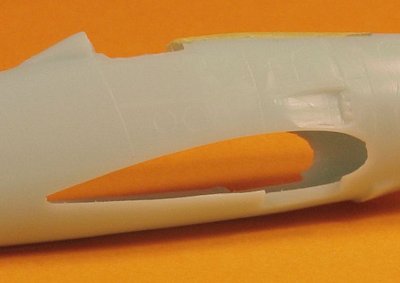
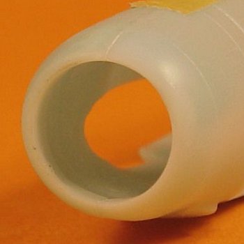
The fuselage had another problem: the cowling opening was seriously unround. The repair job required that the fuselage halves were provisionally glued together with some drops of super glue. First I sanded the face flat, and then I switched to the opening, sanding it with sand paper wrapped around an Xacto knife handle. After this, two dents remained, and these were built up with super glue mixed with sanding residue. One of these dent repairs can be seen in the 11 o'clock position. After I shot the photo, I modified the cowling opening some more, since I think the opening is a bit too large. I glued a strip of plastic card all around, and then smoothened the interior with some Milliput.
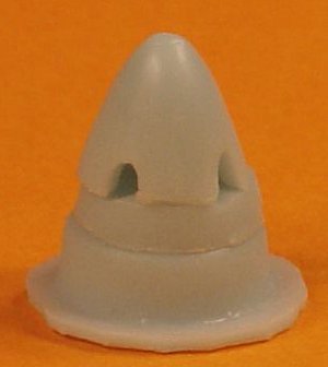
The last item I worked on was the spinner. The spinner parts are seriously canted at their contact area. The position shown in the photo is best of four possible positions, and still not very good. The lower part is reported to be part of a Constellation cowling, but its shape is too simple. Also, in its original shape, it completely blocks the (admittedly limited) view of the engine, so I largely removed the face that blocks this view. These parts are all best replaced in my opinion, and I found some parts that appear suitable. More later.


Modeling links


Return to models page