Airfix Four-Stroke Engine
| In the last sixty years, model companies have issued some thirty-five different 'visible engines', of which I made this visible engine scale models overview. Best known is the 'Visible V8' by Renwal and later Revell, but models of four-cylinders, six-cylinders, rotaries and radials were also produced. Most models have transparent plastic, others have cut-outs to show the internals. This Airfix model was the first visible engine kit that I built.
|
The model
This Airfix model was first issued in 1972. Forty years later, in 2012, it was re-issued, and that is the issue that I got. Apparently, it was reissued again in 2014, in another box.
| 
| 
|
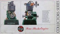
| C701S and/or 07551-4 (1972)
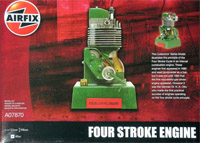
| A07870 (2012)
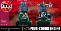
| A07870 (2014)
|
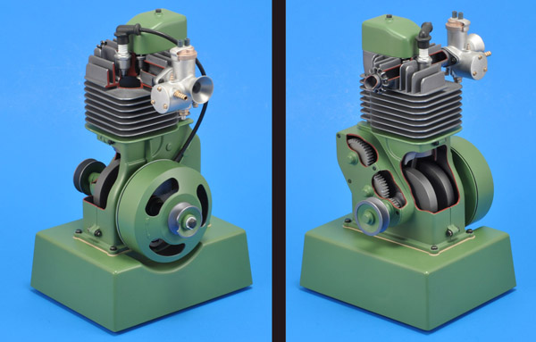
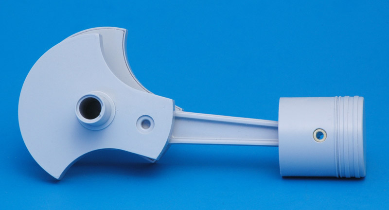
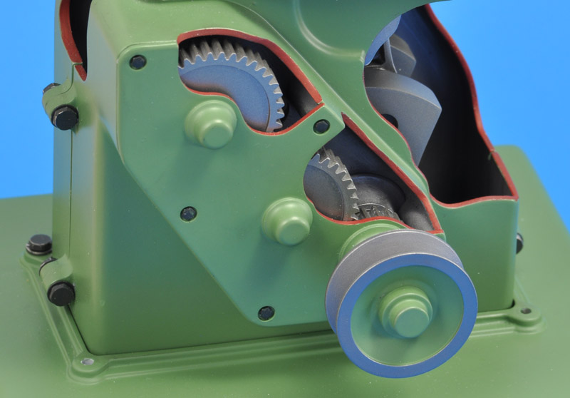
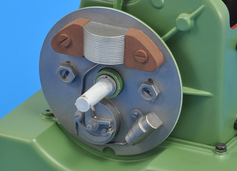
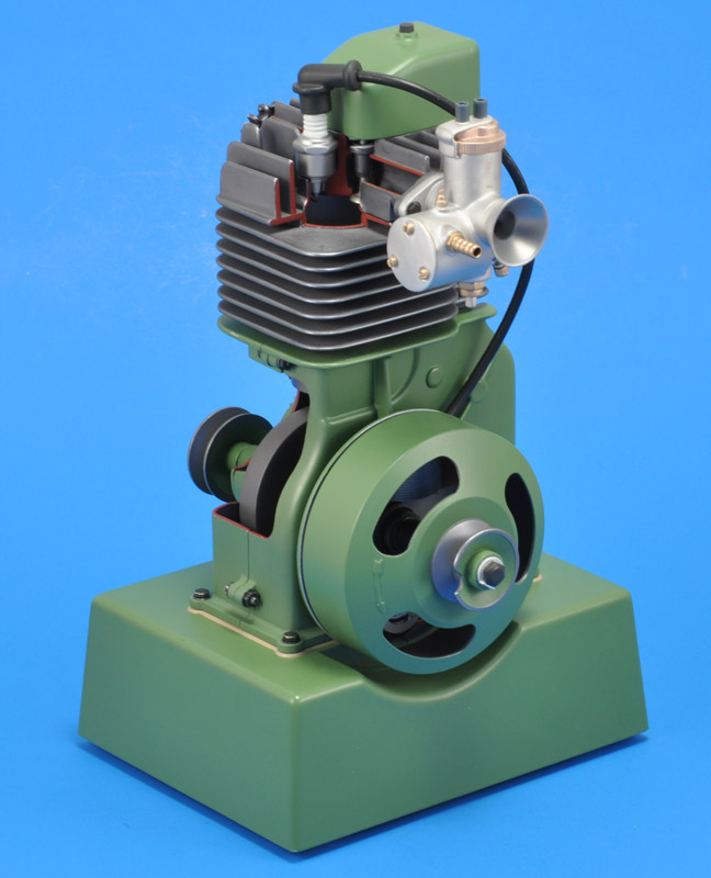
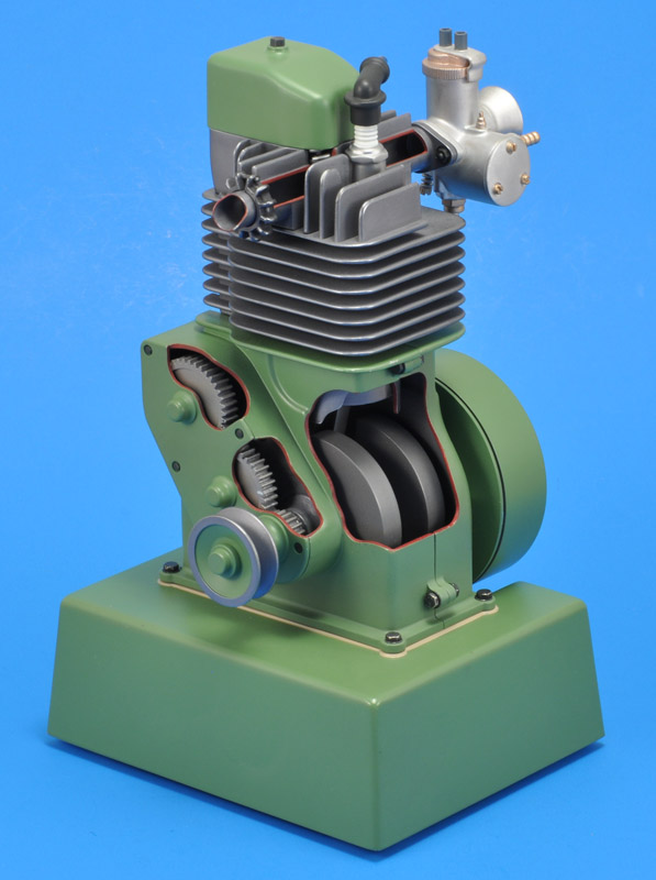
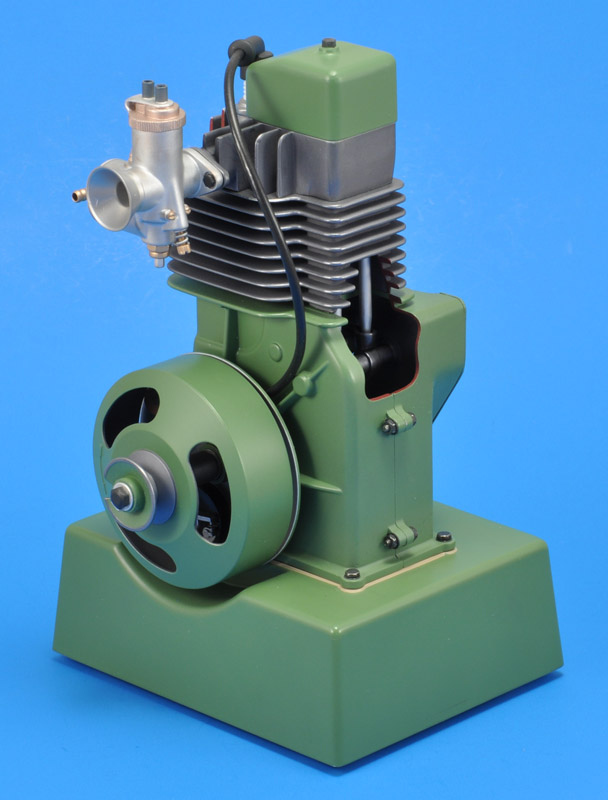
As far as I know, this single-cylinder air-cooled four-stroke engine model is not based on a real engine. Airfix does not provide any background information. To me it looks like an instruction engine that one could find at a technical school. I measured the stroke and bore, 30 and 24 mm respectively, and that makes 14 cc. The model has a rotating crankshaft, moving connecting rod and piston, plus a gear-driven camshaft, pushrods, rockers and valves. The ignition is magneto-style. On the magneto side, there's a rope-start pulley, that has a cut-out to hook the knot behind. The other side of the crankshaft has a regular pulley that theoretically could drive some equipment with a belt. The model has various cut-outs to show the internals and the working, and only the small valve cover is removable.
A few years after finishing my model, I finally spotted a small engine that somewhat resembled the Airfix engine, in this video: Antique Villiers Engine Restoration. If you leave off the forced air cooling (both fan and ducting) and fuel tank, and squint, then you can see a rough resemblance. The video shows a stationary Villiers Model 15 engine, but maybe there are better matches in the Villiers engine catalog, see for yourself here: Villiers Engine Models.
The kit parts clearly show the age of the model: they are a bit crude, show some flash, and show scratches and other small defects. I found it unusual that only the last step of the instructions shows how to paint the model. The instructions of the original issue showed how an electric motor plus battery could be installed. My second issue still has the plastic parts of that motorisation, but the instructions do not show this option. The cost of the model in 2012 was 18.50 euros.
Construction
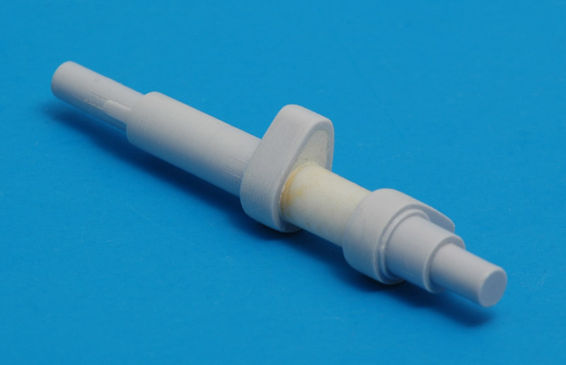
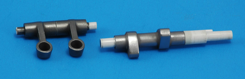
| The model has one serious problem, and you encounter it right away in the first build step. When the crankshaft is assembled, you will see that the cranks are not lined up, and similarly the outer shafts are not aligned. You cannot install it as is: the crankcases needed to be off-set, and the engine would not turn at all. This problem was already present in the first issue, shame on Airfix for not correcting this.
| 
|
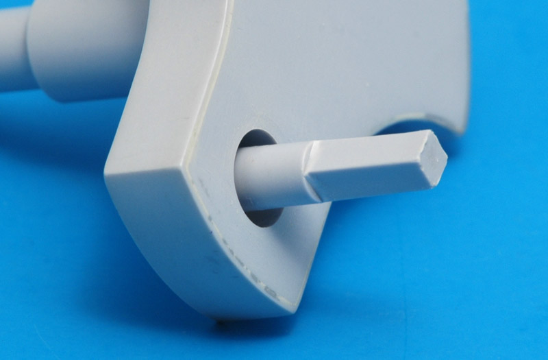
| The crankshaft problem is caused by the square key on the crank pin (crank throw). I solved it by dipping the key in boiling water until it was soft(ish), then quickly assembled the crankshaft and twisted the key until the cranks lined up. If you look closely you can see the white discolouring of the deformed area.
|
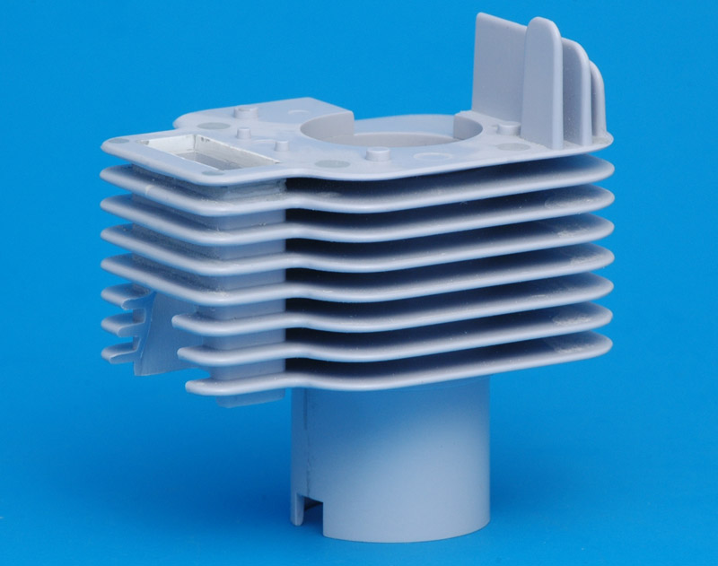
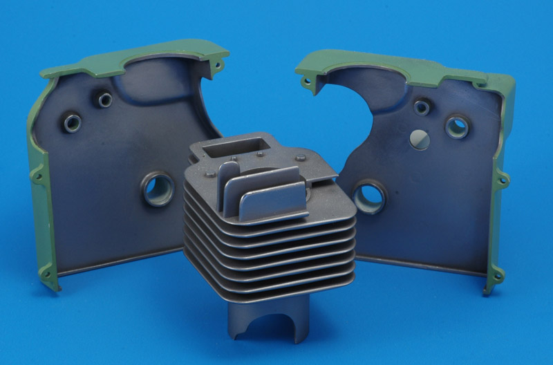
| The cooling fins of the cylinder were by far the most laborious part to build and finish to my standards. First the two halves were assembled, then the top fin (23) was glued on. I removed 1 mm from the bottom of that top fin part, to create perfectly equal spacing between all ribs. This in turns means the pushrods need to be shortened by the same amount. The fins needed lots of filling and sanding to make them look like one piece. The cylinder wall showed shrinkage from the fins, and therefore also required filling and sanding.
| 
|
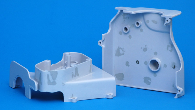
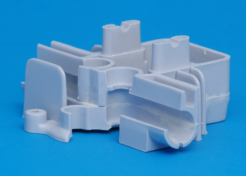
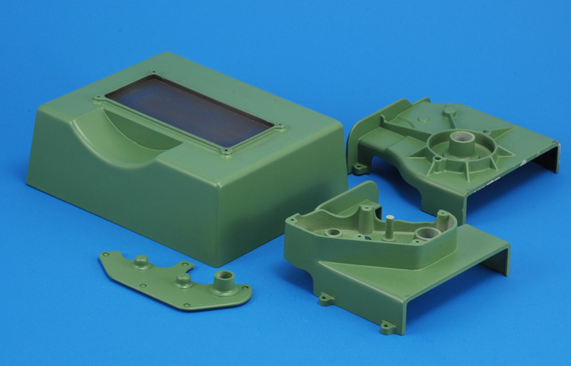
| The two crankcase parts showed a lot of roughness on the inside: many ejector pin marks and other defects that required filling. In the outside too shrinkage areas needed filling and sanding. More filling was required for the bolt flanges. I removed the four moulded-on bolts and nuts that 'connect' the crankcase halves. I found them slightly misshapen and too difficult to paint. Instead I obtained M2x10 hex-key bolts and nuts.
|
| The camshaft looked awkward, with a small-diameter axle connecting the hollow cams. I solved the former with a piece of plastic tubing, and the latter with Milliput.
| 
|
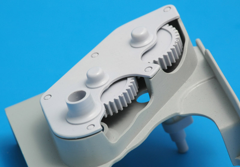
| The casing for the camshaft gears had an inconsistency: on the bottom, both casing and cover had a cut-out, but at the top there only was a cut-out in the cover. I added a cut-out in the casing. The 'AIRFIX' lettering on the cover was removed since I did not like it.
|
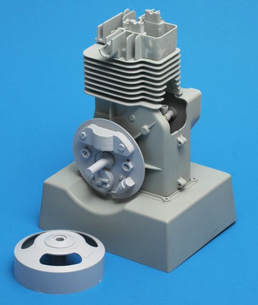
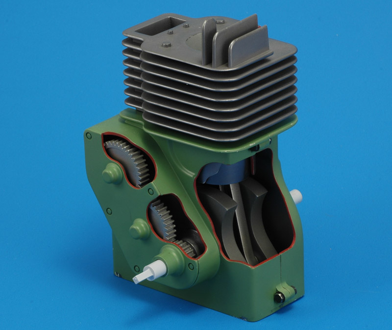
| Here's an intermediate result, with most of the above assembled dry. The crankcase parts were painted with a grey primer. Overall, I was happy with the results so far.
| 
|
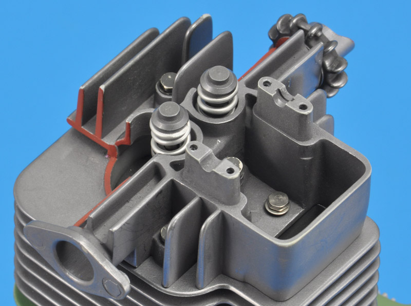
| The cylinder head was very difficult to build properly. The fit of the parts is definitely rough, and to make it look like one part required filling and sanding in places that are really difficult to access. I removed all bolt heads, to replace them with metal M2 hardware. It makes painting so much easier and looks better.
|
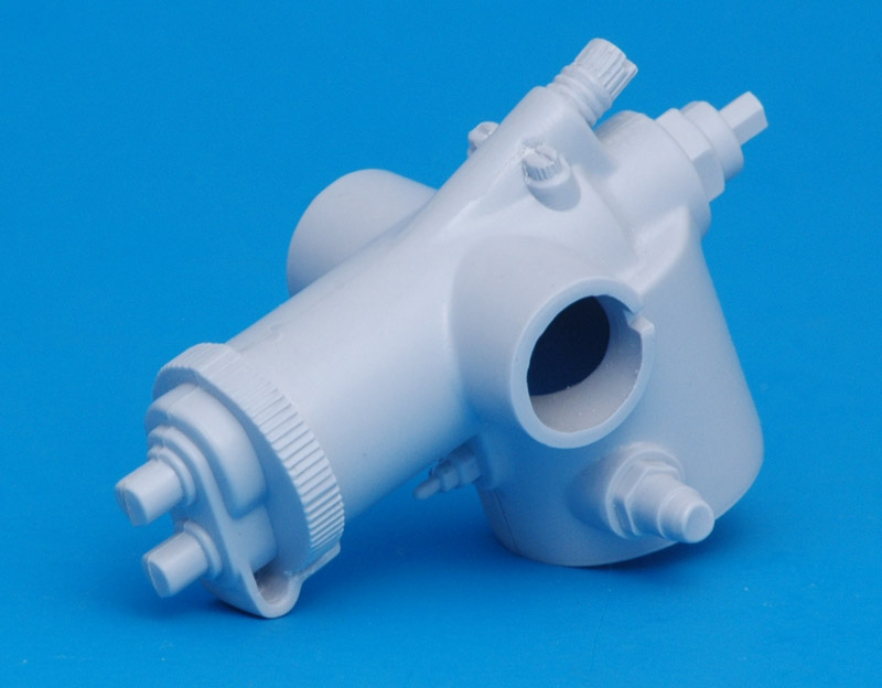
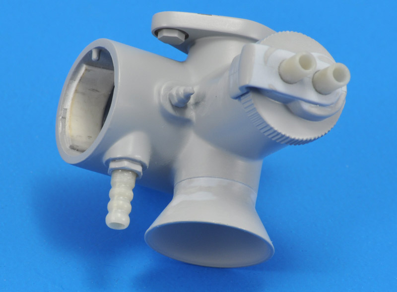
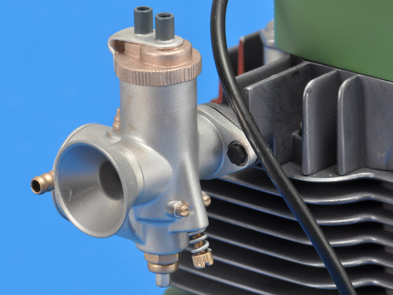
| Thee carburettor was another part that took some time to look realistic. I used a JLC razor saw to scribe lines under every nut and bolt and axle, to visually separate them from the main body, and thus add a bit of realism. That work wasn't finished when I made this photo. A bit of a problem is that I don't know anything about carburettors, and I have little idea what the various bits represent. Lastly, the 'AIRFIX' lettering on the carburettor (not shown here) was removed.
| 
|
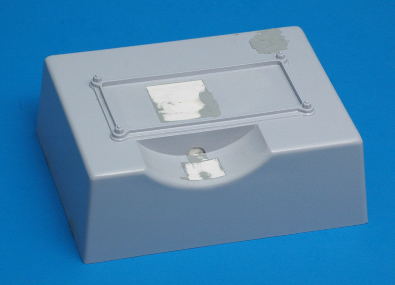
| The base contains traces of the motorisation of the original issue. I closed all holes with 1 mm plastic card. I also removed the mounting points for the name plate, that I thought I would not use. A technical comment is that engine has no (simulated) sump, probably because of the motorisation.
|
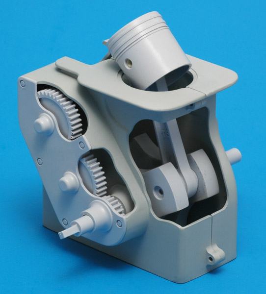
| Another intermediate result, with most of the above assembled. New is the magneto ignition. All parts are now painted in a grey base coat, in order to judge the build quality.
| 
|
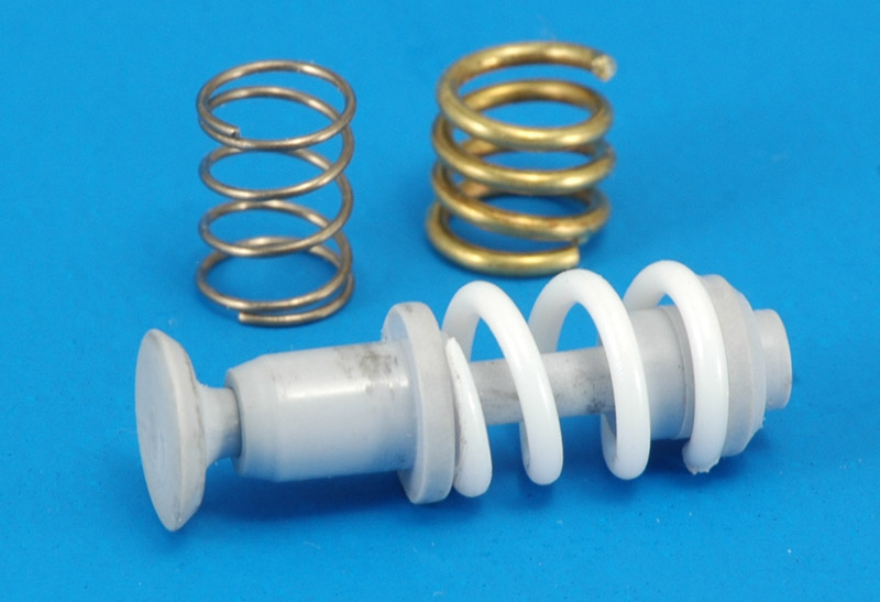
| The metal valve spring that Airfix included (top left) are functional, but don't fit with the 'picture' of the engine because of their small gauge. First, I tried making replacements from 1 mm brass wire (top right), that looked good but was way too stiff. To my surprise, 1 mm plastic rod could also be wound to a spring. You need to use a smaller diameter die, because of the springback of the material. The spring stiffness was just right.
|
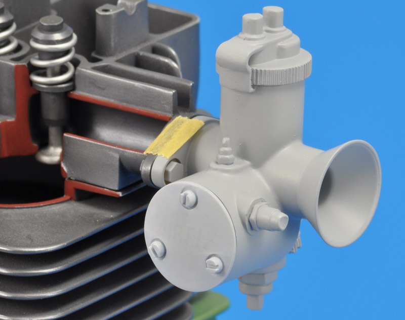
| At a late stage I found out that the mounting of the carburettor on the cylinder head had a problem: there is only a flange on the cylinder head side. You need two flanges for a connection of that type. I cast a resin copy of the flange part, and fitted that to the carburettor. The flange on the cylinder head was carefully mounted and its glue joint filled to a radius, to make it look like a single part.
| 
|
| I had no idea what the various bits and pieces on the carburettor represent, which makes it difficult to decide on the colours. I started by making lots of scribed lines around the bolt heads to separate them visually from the main parts.
|
| I got great help from the fellow modelers at the MCM forum, and learned that the Airfix carburettor closely resembles some types of Amal carburettors. A bit of study taught me all I needed to know to finish the kit part.
| 
|
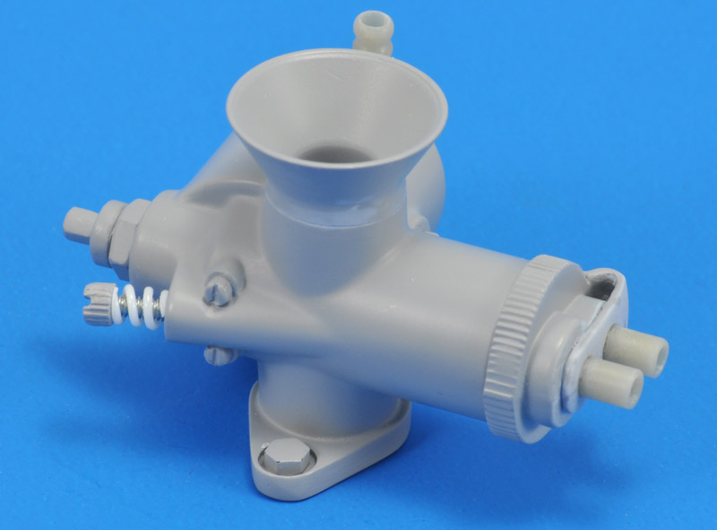
| Now that I understood the various parts and details, I modified the carburettor a bit. I scribed a line around the velocity stack, to indicate it is a separate part, and to serve as a paint demarcation. I cut off the set screw on the left, glued in a length of M2 thread, rolled a spring from plastic rod, and reinstalled the screw head. On the top side (right in the photo) I cut off the two unround cylinders, and replaced them with 3.5 mm tubing. Maybe I will add throttle and choke cables coming through them.
|
| On the right side of the float chamber, I cut off the simulated fuel tube. To clarify its function, I replaced it with a piece of tubing that I gave barbs by using my motor tool as a lathe.
| 
|
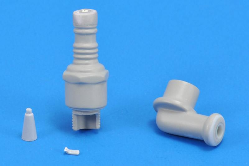
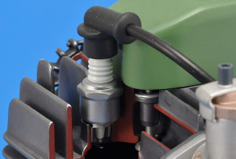
| The last part that I built was the spark plug. I modified it several ways, mostly to make painting easier. On the top side I cut off the spark plug boot, and extended the spark plug so the boot could be pushed on. On the bottom side I cut off the spark plug centre electrode and its insulation, so I could finish and later paint the interior of the spark plug. The ground electrode broke off during handling, and will be replaced.
|
Painting
There's never a hard line between assembly and painting in my modelling projects, but nevertheless I will make that division here. Airfix gives some painting instructions, but since there is no original, you can do whatever you like. I studied various other models to learn what colours I liked and did not like. Most I did not like! The yellow interior was maybe the worst of the colour recommendations. Bright green for the crankcase, and rust for the metal parts are examples that looked unsuitable to me. But maybe each country has its own traditions for paint colours of machinery.
The best metal colours I knew are the Humbrol Metalcotes. I made test pieces of the four available colours: 27001 Matt Aluminium, 27002 Polished Aluminium, 27003 Polished Steel and 27004 Gun Metal. The first two were a bit of a disappointment, they did not buff and did not look very metallic. The last two are very nice, they look great after buffing. 27004 Gun metal is quite dark though, and looked suitable only for cast metal parts, like the crankcase. That left 27003 Polished Steel for all machined parts, which was a bit limited.
| 
|
| To try to create more metal colours, I decided to try to mix 27003 Polished Steel with regular Humbrol colours. 3:1 or 2:1 mix of Polished Steel with grey, yellow, brown and blue gave me colours that hardly deviated from the original Polished Steel colour, and with a 1:1 mix the buffing effect was lost. Therefore, this experiment unfortunately did not yield a solution.
|
The search for the right shade of green was a very long one. I knew what I was looking for: that typical green used for older factory workshop machinery in Europe. But I had no idea what its colour code was.
The start of the answer was found in a DIY store, that had a huge rack of colour cards, for colour matching at home. There I found a few shades that came close to what I had in mind. I compared the best one to a RAL paint deck, and found RAL 6011. That code in turn yielded the colour name 'machine green' on many websites, confirming this was the colour I was looking for.
Last step was mixing this colour from model paint. I used Revell enamels, and found that a 2:1:1 mix of 360:374:378 gave me RAL 6011. I filled a 14 ml tin of this mix, and then painted the main parts in this colour.
| 
|
| After masking I painted the interior of the crankcase Humbrol 27004 Gun Metal, and the cylinder Humbrol 27003 Polished Steel. I will try to use different metal paints to create a bit of variation, but the colour differences are quite small.
Not shown earlier was the additional cut-out that I made in the cylinder liner, at its lower end. I added (removed) this because otherwise the piston would only be visible from the top. I think I saw this modification on another Airfix four-stroke engine.
|
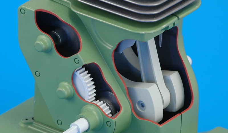
The last main colour choice was the shade of red for the edges of the cutaway sections. I had seen examples using a bright red, and that just looked wrong. A darker 'blood red' seemed to work far better. I decided to use an acrylic paint, so corrections would be easy. It is a 2:1 mix of Vallejo 70.909 Vermillion and 70.814 Burnt Red.
This photo shows an inconsistency in the style of the cutaway sections. Most of it is curvy, as is preferred to show the randomness of the cutaway, but half of the crankcase cutaway is done with almost straight lines. It's unfortunate that I noticed it only now, otherwise I would have changed it.
| 
|
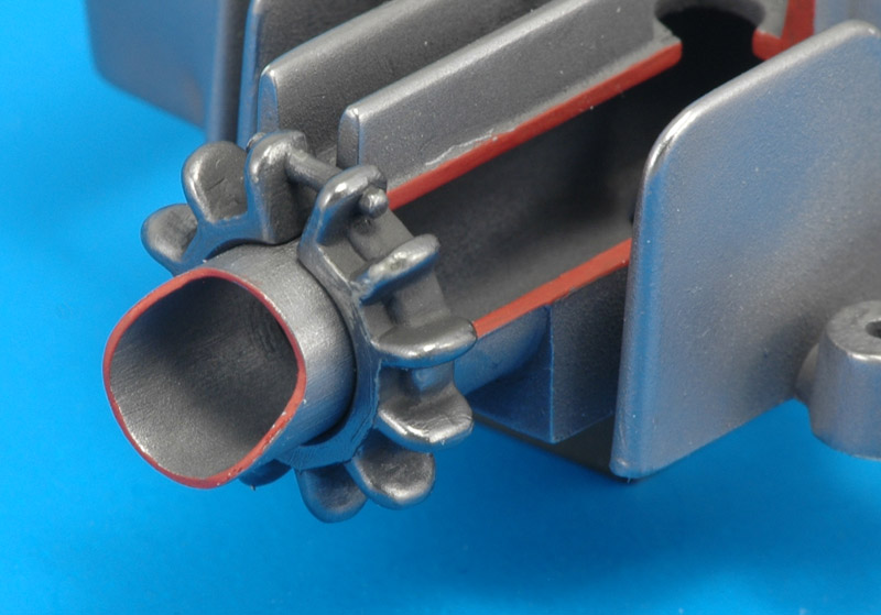
| Diverting from the painting for a moment. The clamp that connects the (short) exhaust tube to the cylinder head was very rough with lots of flash, and required a lot of work to make it presentable. I cut away some material to make the function of the clamping bolt visible. The exhaust tube's wall thickness looked excessive, and I thinned it considerably.
|
|
The camshaft was painted Humbrol 27003 Metalcote Polished Steel again, the cam followers were done with Humbrol 27004 Gun Metal. Both were buffed with a soft cloth. The gun metal is a bit dark, but some colour variation was needed. I left the parts that would be bearing surfaces clear of paint, as much as possible.
| 
|
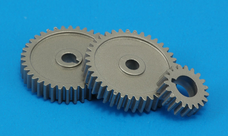
| The camshaft gears were painted MRP-030 Steel. This paint is not as nice as the Humbrol Metalcotes, that can be buffed to create a more realistic metal look.
|
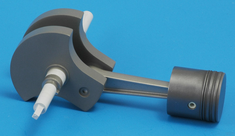
| The crankshaft was painted with a mix of Humbrol 27003 Polished Steel with another Humbrol colour (lost the notes), the connecting rod MRP-030 Steel, the piston Humbrol 27004 Gun Metal. I did not paint the piston rings, since they would never be seen again after assembly.
| 
|
| Finally, the assembly could be started. I closed the crankcase with stainless steel M2x10 hex bolts, nuts and rings. All were painted Revell 9 Coal Black. The cylinder was mounted on the crankcase using epoxy glue.
|
I have a hard time understanding what Airfix wants to portray on the base.
More assembly: the crankcase was mounted on the base. The base is maybe a bit large for the engine, as a result of the earlier motorisation, but it's too late to change that now. I filled the base partially with plaster of paris. This give the model better stability, and makes it more realistic if you pick it up.
| 
|
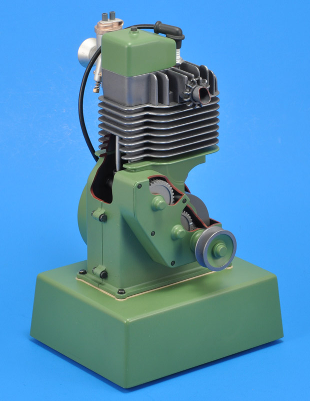
| The small pulley on the camshaft gear side of the block was painted Revell RAL 6011 and Humbrol Polished Steel. I imagined the part was a steel casting or a forging, turned on a lathe, and that decided the division between the two colours. I decided not to use the optional crank handle.
The tiny recessed bolt heads on the camshaft gear cover were really difficult to paint. I could not think of a way of masking them properly. In the end I decided to paint the sides of the bolt heads with a tiny scalpel knife. I dipped it in paint, wiped one side of the blade clean, and applied the paint to one of six sides with the other side of the blade.
|
| Airfix gives no painting guidance for the magneto ignition parts. I looked at real ones to decide on the colours. All will be quite hidden behind the flywheel though. Here work has just started with painting the coil at the top. Later I filled the slots / openings in the largest bolt heads - I have never seen a bolt like Airfix moulded.
| 
|
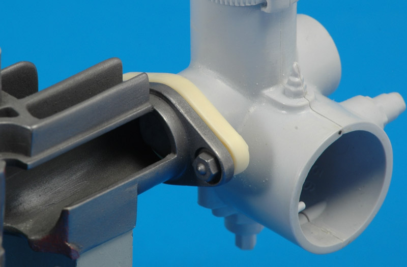
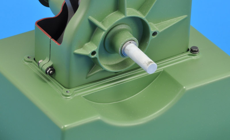
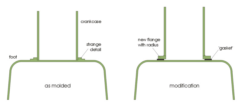
| Here's another status photo. The finish line is in sight I thought! However, I had ignored a problem that I never managed to solve: I just don't understand the detail that Airfix moulded on the foot, that should represent the way the crankcase connects with the base / foot. Is this supposed to be a clamping ring, with a gasket? Or does it represent a flange of the crankcase parts, and should I fill the gap to make a smooth transition to the crankcase? It's way too thin for both options.
|
| I asked for advice on both the MCM forum and Britmodeller. The 'flange' solution made most sense according to the majority. Here's what I'm thinking of doing.
| 
|
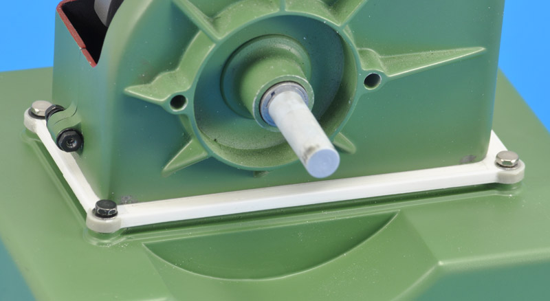
| I built the two flanges from polystyrene strips of 2.5 x 2.5 mm, two next to each other, but the width was insufficient. I added one millimetre, and that improved things. For the rounded corners I used one half of a 1/72 rocket pod body. The flanges are not attached to the crankcase yet, therefore there is no radius filled in either. The original detail under the new flanges still needs to be partially sanded away, so the flange will sit on the gasket.
|
I created a fillet with Apoxie Sculpt, with small cut-outs on the corners for the bolt heads. Next was the paint, from a freshly mixed batch.
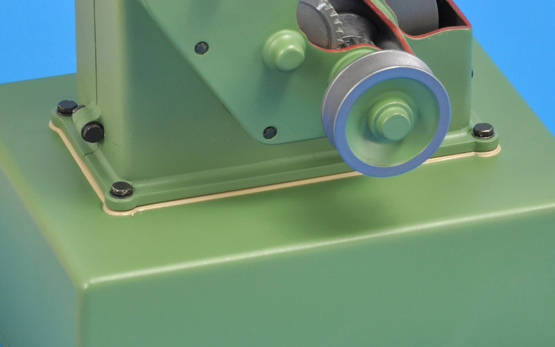
Initially I had no inspiration what colour to use for the gasket. I searched for (random) gasket images, and eventually decided on a cork-ish colour. The first colour I found in my collection that came close was Xtracolour X812 FS23446 'Gulf Sand'. After a lot of masking the job was done. It wasn't perfect because the 'gasket' edge had a radius / fillet where it touches the base. If I would build it again, I would change this before painting by scribing.
| 
|
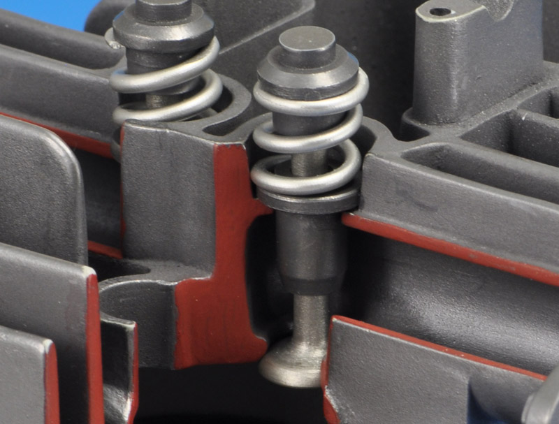
| For the valves I used three colours. The valve was painted MRP Steel, the spring MRP Silver and the valve guide Humbrol Metalcote 27004 Gun Metal. I'm happy with the result, it looks properly 'busy'.
|
| I glued the cylinder head on with dots of epoxy glue. Next, I installed the M2 bolts and rings in all places where I had previously removed the plastic bolt heads. I painted them Revell 9 coal black, and scratched them a bit to reveal the original metal colour. The bolt head on the right still needs to be painted.
| 
|
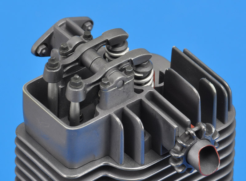
| I painted the rockers Humbrol 27004 Gun Metal with Revell 9 nuts. The pushrods were painted MRP Silver. Before assembly, I superglued one layer of paper around the rocker shaft, to eliminate the play.
|
| The spark plug had a simple paint scheme: MRP-135 Insignia White for the ceramic parts, and MRP-031 Chrome for the metal parts. The separate boot was painted Revell 9 Coal Black. I replaced the Airfix spark plug lead, that had an oval cross section, by a similar length of co-ax wire.
| 
|
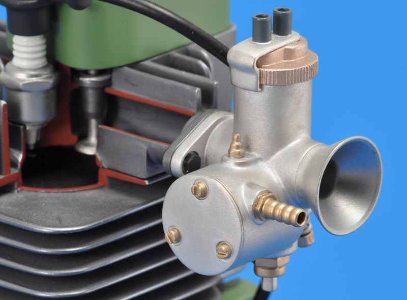
| The painting process of the carburettor wasn't a great success. I started by painting most brass screws and other details. I did not have a brass model paint, but on my Humbrol paint chart, their brass looked a lot like gold. I used Humbrol 16 Gold, mixed 4:1 with Humbrol 27001 Aluminium. For the top cap I used a similar mix, but using Humbrol 12 Brass. The results were not really brass-like though. After a ton of masking I was ready to paint the main body. I did not know of a model paint for zinc or Zamak parts, so I decided to use Humbrol 27001 Aluminium. That turned out rather grainy, and required hard buffing that removed the paint in places.
|
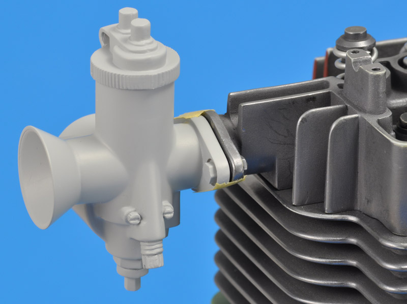
| Next were the metal clip on the top cap and the velocity stack. After much more masking I painted it MRP-031 Chrome. It had a subtle different colour, but the roughness of the Humbrol 27001 Aluminium showed through; only the interior of the velocity stack ended up looking like I expected - the third disappointment. Lastly, I painted the cable tubes dark grey and the mounting bolts Revell 9. I used epoxy to glue it to the cylinder head.
| 
|
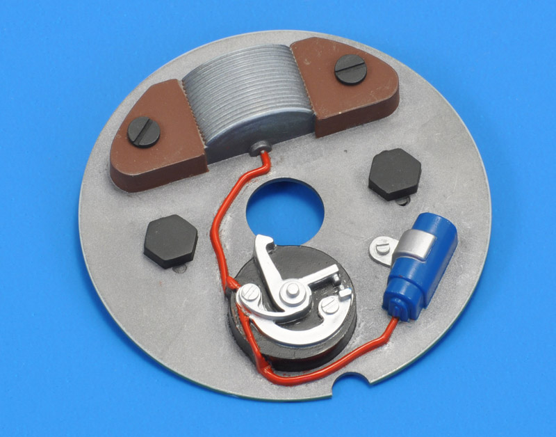
| The last paint job was the magneto ignition - I still had to paint some details. It required an almost silly amount of work to mask it all - the price one pays if you don't want to brush paint. And all of this effort for something hidden inside the flywheel..
The bolt heads had recesses with a slot, a bolt head configuration that I had never seen. I filled them to make normal hex heads, and painted them Revell 9 coal black. The slots underneath the bolts are a nice touch, in reality it would allow adjustment of the ignition timing.
The magneto was brown with Revell 9 coal black screws. The points: a mix of MRP-005 Black and MRP-040 FS 36118 for the base, MRP-128 Silver for the mechanism. The capacitor was painted MRP-045 Ukraine AF Dark Blue with an MRP-128 Silver clamp. Lastly the wire was painted MRP-184 Signal Red. The masking was not perfect, but little can seen, once installed.
|
The result
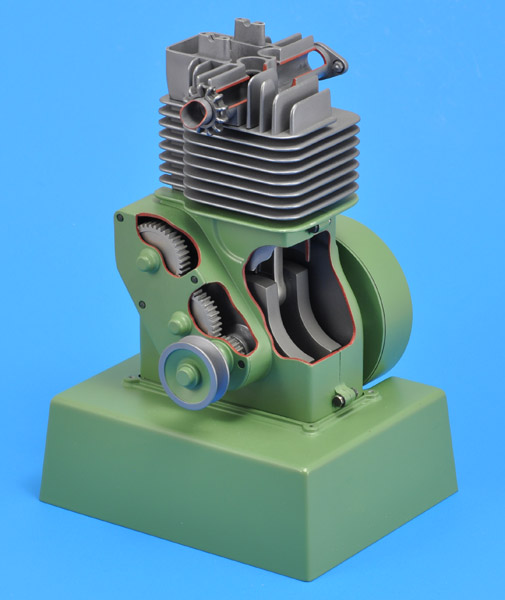
| It was a major project, but I am very happy with the result. The work spent on finding good colours payed off, I think. RAL 6011 'machine green' looks so much better than apple green as suggested by Airfix.
| 
|
| The work spent on creating various steel colours is not very visible, unless you study the model very closely. Humbrol Metalcote really needs an undercoat - it rubs off too easily, showing the plastic colour underneath. I had to touch up the model in various places.
|
| I'm happy that I removed the 'Airfix' lettering on the camshaft gear cover and carburettor, plus the 'four-stroke engine' plaque on the base of the model. It would have detracted from the appearance.
| 
|
| The colours of the carburettor are a bit too bright to my taste, but they do create a nice contrast with rest of the engine.
|
Conclusion
This model requires quite a bit of work if you want to build it properly. The parts really show their age, but with careful work, a nice model results. The model gives the impression that the kit designers or the mould makers did not always understand what they were trying to portray; some details do not make sense. The value for money is right I would say. I'm happy that I made a careful study of the colours that would suit the model, I'm really happy with the end result.
Links
Return to models page