Scratch-built 1/72 Lambach HL II
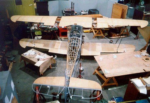
Photo courtesy of SSVOBB
| I enjoy the construction part of building a model, and I've scratch-built quite a few components. I had never attempted to scratch-build a complete model though. The perfect moment arrived when I thought about building a model of the Lambach HL II, a replica of which was under construction at the faculty of Aerospace Engineering of the Delft University of Technology. A student organisation called 'Stichting Studenten Vliegtuig Onderhoud, Bouw en Beheer' or SSVOBB for short had started this project in 1988, and the replica first flew in 1995. I started construction of my model in December 1993, but I haven't worked on it in years now (the story of my modeling life :-). But I will finish it, it is just too nice! I will possibly cast some copies of the model, but that's for later.
|
References
I had the best references one can think of: factory drawings, plus a replica under construction, at arms length! The SSVOBB people (Alfred Roelen in particular) were very helpful to lend me drawings.
A book on the Lambach HL II was written by Nijenhuis and Spek, published by Barjetesh, Meeuwes & Co (ISBN 90-5613-016-1, Dutch language). It describes the history of the Lambach HL II aerobatic aircraft built in the Netherlands in 1936, and the process of building the replica. De 'Nederlandse Vereniging van Modelbouwers' has a drawings library that includes Lambach HL II drawings in 1:10 scale. Ordering number is 50.00.023, price 13.25 euro for members and 19.75 euro for non-members.
Construction
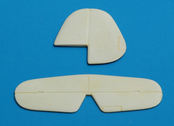
| I started with some simple components, to see how difficult things would be. The simplest components are the tail surfaces. I drew their contours with a very sharp pencil on plastic card of suitable thicknesses, and cut it out. Then I sanded the components into an airfoil shape. What remained was to scribe the hinge lines and the trim tabs. And ready they were! I believe they took less than an hour each. By the way, if you think the components are too thin, you are partly right. The SSVOBB people called them jokingly 'supersonic' sections because of their very limited thickness (3% I believe).
| 
|
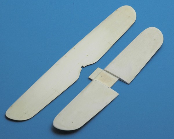
| Encouraged by the success with the tail surfaces, I built the upper wing as the next component. The basis was formed by two pieces of 1 mm plastic card glued together. Again the planform was drawn carefully with a very sharp pencil, and cut out. Next I sanded spanwise, to thin the 'plank' progressively towards the wing tip. This was only done on the lower surface, since the top surface is flat. Last step was to sand the plank into an airfoil shape. I haven't scribed the ailerons yet. A handhold in the trailing edge unfortunately broke off, but can be repaired again.
Much later I built the lower wing. This was done in a largely identical way as the upper wing. I cut away most of the wing in the middle, to make it fit under the fuselage, and form the cockpit floor. For this reason it was also extended forward.
|
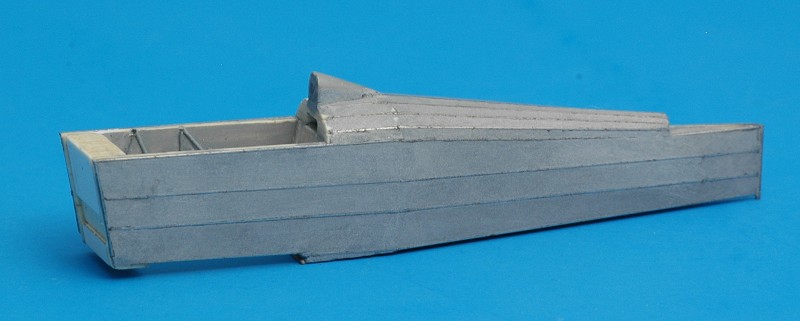
| The fuselage was a much bigger challenge, with its 'fabric over stringers' exterior. I started with the two sides of the fuselage. A piece of 0.7 mm card forms each fuselage side from the firewall to the stern post. On this plastic piece, I glued pieces of 0.3 mm steel wire, representing the stringers. The space between them was filled with Tamiya putty. This created a very accurate representation of the fabric. I then detailed the cockpit interior (see below). To form the actual fuselage, I cut solid plastic card bulkheads, and glued them between the fuselage sides. Then I folded the rear ends of the fuselage sides towards each other, and fixed them with glue. The rear fuselage was then closed with more plastic card, and filled with epoxy resin to make it a solid component.
| 
|
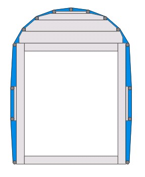
| This drawing shows the construction method with a cross section of the fuselage. Plastic card (light gray) is the basis, onto which 0.3 mm steel wires are glued. The two middle wires on each fuselage side are 'raised' by gluing them on additional pieces of card. The space between the wires is then filled with putty (Tamiya in this case) and then sanded with a flat file until the wires surface from the putty. |
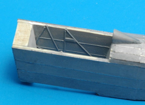
| In this photo shows the detailing of the cockpit. I represented the steel-tube fuselage with 0.3 mm steel wires, half recessed in the plastic. I also added pieces of stretched sprue to represents the horizontal wooden longerons, that can also be seen on the exterior. Just visible is a trim lever attachment plate on the side of the cockpit. Due to the thickness of the plastic fuselage sides, the cockpit is slightly too narrow, but this cannot be avoided. The front firewall was made way too thick, to allow for holes for the main landing gear to be drilled in it. You will not be able to see it from the cockpit opening later.
| 
|
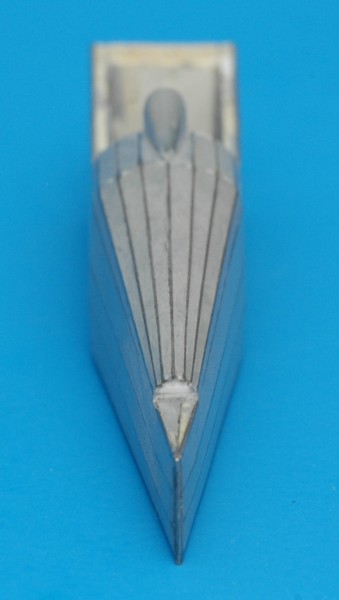
| The biggest challenge so far was the 'turtle deck' of the rear fuselage. Initially I had no idea at all how to build it. After more staring at the factory drawings, I found a solution. I built components that are best described as a 'winners podium', but with more steps. The rear one was truely tiny (2 by 1 millimeter I believe, you can see it at the rear end of the turtle deck), but with the help of calipers I managed. In the corners of each step I glued a steel wire, and then the remaining volume was filled with plastic and Tamiya putty. The end result is nearly perfect, if I may say so myself. A headrest fairing was built on top of the turtle deck.
|
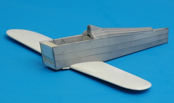
Here the lower wing and fuselage are seen assembled. A lot of work is still to be done. First on the list is the engine cowling, and the cockpit cover. Next will be the landing gear, and then the interplane struts.
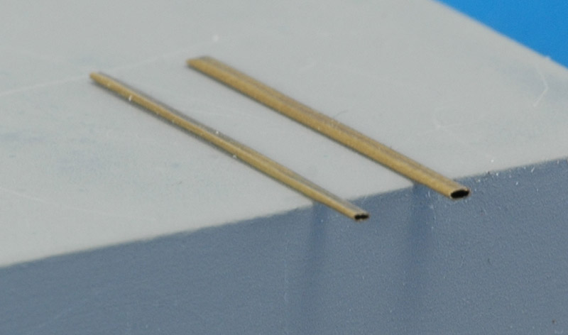
With the Contrail strut material no longer in production, I tried to find an alternative. I found a sweet technique to make the interplane struts: by rolling Albion micro tubing almost flat. Since Albion tuning is available in 0.1 mm step sizes, you can achieve any size of strut material that you need.
| 
|
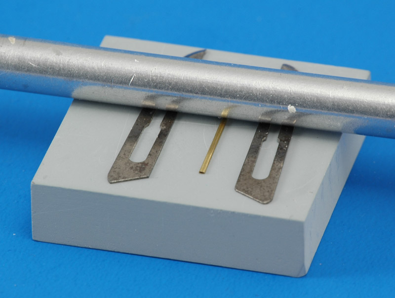
| I experimented with Albion micro tubing to make streamlined struts. Albion sells a special tool that does roughly the same. My rolling method often gives curved struts, but you can uncurve them by rolling the other side.
|
As you can see, the rolled struts develop a slight figure 8 shape. For a next experiment, I would try inserting some stretched sprue in the tubing before rolling.
I recommend getting four 'Slide Fit' packs from Albion; I have SFT1, 2, 7 and 8, from their brass range, covering 0.3 mm to 1.8 mm in 0.1 mm increments. Aluminium and nickel-silver are other options, but their sizes only cover 0.3 to 1.0 mm. Here's the 2020 catalog.
| 
|
Differences between the original Lambach HL II and the replica
The model that I am building is a replica of the replica. The replica differs in a small number of points from the original. This was usually caused by drawings showing different details than surviving photos. One such difference could be the shape of the turtle deck. Photos seem to show a continuous slope from the cockpit to the tail, instead of the kinked shape that the replica has. Another small difference is the tail wheel, which was given extra control arms and cables because it proved to be 'twitchy'.
Links
- Albion Alloys who sell micro tubing that could be useful as struts
Return to models page


