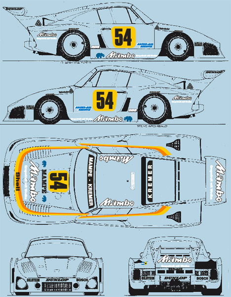
Nunu 1/24 Kremer Porsche 935 K3
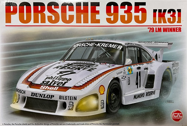
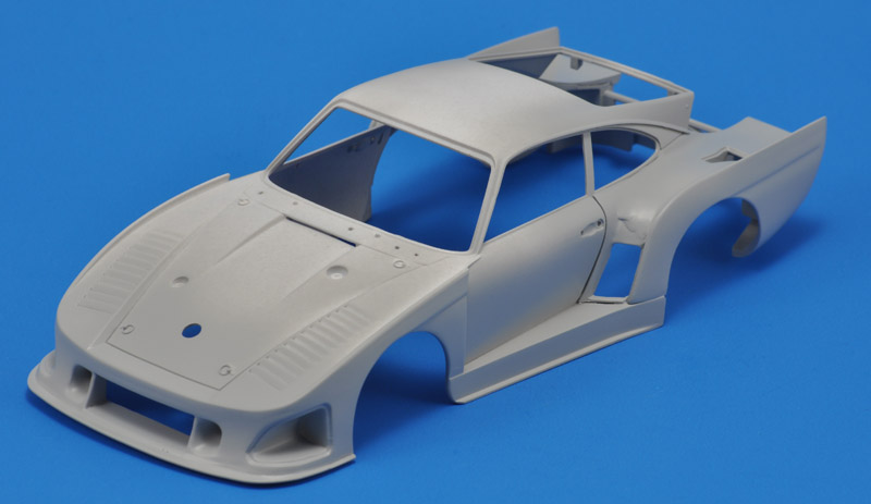
| I had looked forward to getting this new model, but once I had it in my hands, disappointment set in. The body has severe shape problems, it really doesn't look like a Porsche 935-K3. It would be a difficult undertaking to figure out the required corrections, since there are no simple established methods for finding the errors. And it would be an equally difficult task to apply the modifications to the model. The only positive aspect is that its an interesting challenge to develop my 'shape judging' skills. Here's my best try at creating a better 935-K3 model.
|
Warning!
Much of this page revolves around the shape of this model, that was 'off' in my eye. I did not want to build it, looking as it did. But finding the shape problems wasn't easy, I tried several approaches.
I have this theory that maybe 10% of all modelers 'see' shapes, the remainder focuses on details. Each to his own of course, but it's frustrating for the 'seers'. As an example, I found 13 reviews and build reports so far (see list below), but not a single one mentions body shape problems.
Therefore, if my theory is correct, this page will leave 90% of the readers wondering why 1 or 2 mm could be so important..
General comments on the model
Body shape:
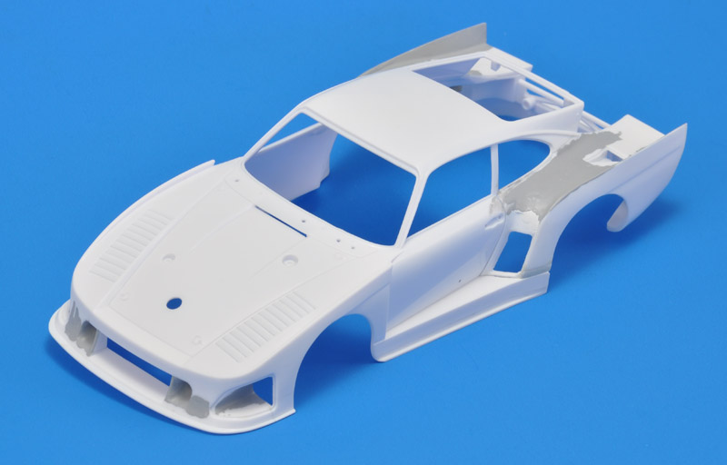
the body looks very weird, not like a 935. If I exagerate, it looks like a funny car dragster, or a mix of a 935 and a sport shoe. The body is too tall. The much smalller Quartzo 1/43 Porsche 935 K3 appears to have similar shape problems. Maybe it was used by the Nunu team as inspiration?
the area between nose oil cooler inlet and the bonnet has too sharp corners, should be rounded. Same for the edge above the headlights.
the air vent (slit) at rear end of the bonnet looks too low
the rear wing sits too high. The complete wing should be 'in the shadow' of the original body according to the rules, but isn't
Details:
the rear fender assembly is very fiddly
there are strong mould lines on the nose and around the headlights
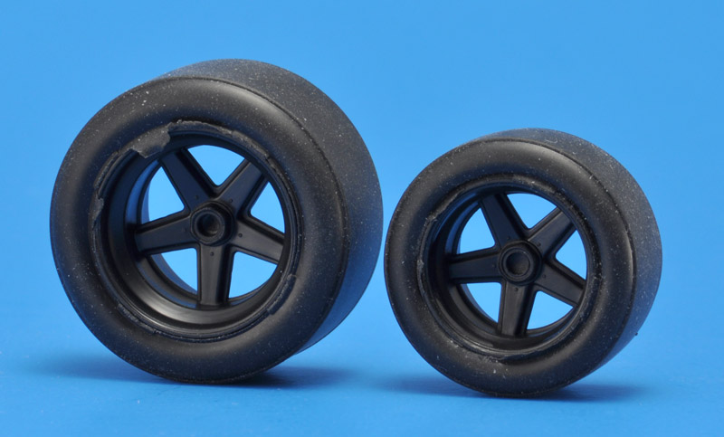
the rear tire looks a bit too big
it's a pity that no rain tires are provided. They would be fitting for the Le Mans 1979 race.
the tires are really difficult. To mount the tires on the tapering wheels, they have raised 'lips' on the inside. Therefore you can mount them only one way. But the outside ends have the most flash. I tried sanding it away, but it's stubborn. Even worse was that I saw the tires delaminate at the flash ends. Nasty.
the circular inlets in the nose have a step inside that should not be there
the intercooler cover (part J16) that occupies most of the rear seat area looks nothing like the real cars I've seen
the panel lines around the bonnet are shallow
the transition from bonnet to door looks a bit off
Nunu 935-K3 reviews and build reports
None of the reviews and build reports listed below notes the body shape problems.
NuNu Models 1/24 scale Porsche 935 K3 1979 Le Mans Winner, Fine Scale Modeler review by Mike Klessig
Porsche 935 K3 '79 LM Winner on the IPMS-USA review site
Pink and white powerhouse Porsche, Key Model World review
Nunu 1/24 Porsche 935 K3 '80 LM- plastic model car inbox review by MM Scale Models on YouTube, with commentary
Nunu 1/24 scale Kremer Porsche 935 K3 by Joel W. on the Motorsport Modeling forum, built as the Apple #9 car
Nunu 1/24 scale Kremer Porsche 935 K3 by Joel W. on the Kit Maker Network forum, basically the same as above, but with different feedback
1/24 Porsche 935 K3. Unbox and test fit #1, Bodywork #2, Chassis + Engine #3, Interior #4, Exterior #5 by Scale Auto Shop on YouTube. No commentary, just video. 1/24 Porsche 935 K3 Full build appears to be a summary
Building a 1/24 1980 Apple 'iCar' Porsche 935 K3 by Calvin Sallee
Building a 1/24 scale 1981 Coca-Cola Akin Racing Porsche 935 K3 by Calvin Sallee
1981 Cooke/Woods Porsche 935 K3 - Daytona 24 hr winner by Calvin Sallee
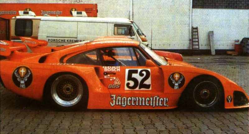
1980 #2 Jagermeister Porsche 935 K3 conversion kit by Calvin Sallee
Platz nunu 1/24 Kremer Porsche 935 K3 Le Mans 1979 announced for October release on the MCM forum
1979 Porsche 935 K3 by Peter Lombardo on the MCM forum, with opening doors, front and rear covers
1979 Porsche 935 K3 by 'Technics' on the MCM forum
Differences between the two Nunu kits
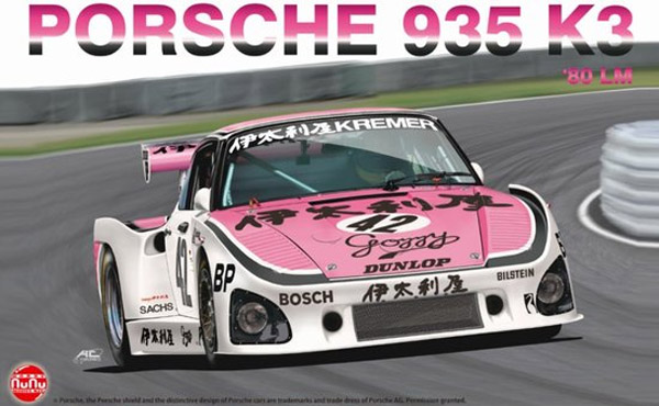
The second issue of the kit, for the pink & white La Moda Goji / Itariya / Italiya version (24029) has some extra parts to build that specific version of the K3:
upper parts of the rear fenders; R8 and R9 instead of L1 and L3. This takes care of the different inlet arrangement behind the doors
revised rear wing, with parts R4 - R7, instead of L7 / L8 / L9 / L10. From measurements of the parts layout in the instructions, I conclude that the wing has a 10% larger span and marginally smaller chord, and the endplates are 10% larger.
an extra set of BBS wheels is included
|
| 
|
First shape analysis
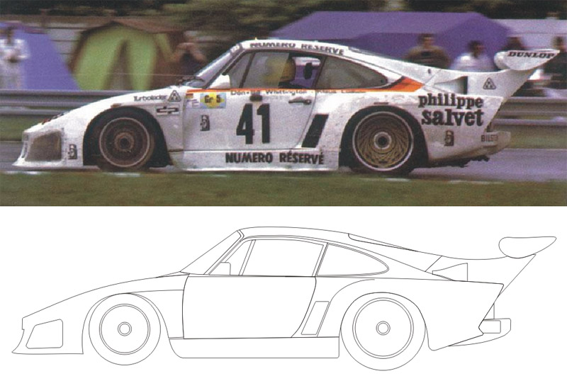
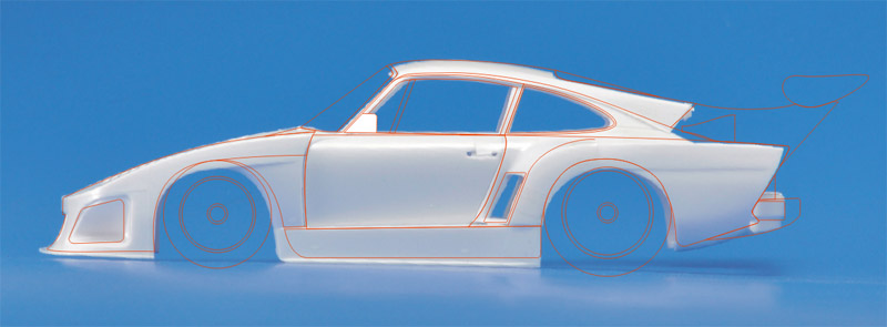
| For the first attempt, I looked for a telelens photo of the K3, showing it from the side. I found a great photo, and drew a line model over it in CorelDraw.
| 
|
| I rotated the line drawing 1 degree forward, flattened the tires, and laid it over the model photo. As expected, the fit was horrible, mostly due to the model's distortion due to the perspective. At least it confirmed my impression that the model's body was too tall.
At this point I stopped these rather futile attempts. It's better to wait for the model.
|
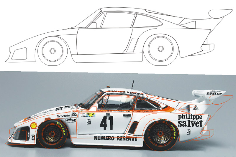
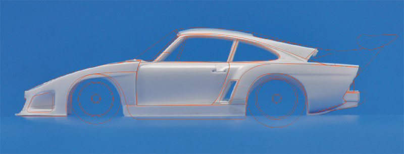
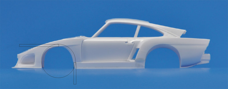
| And here's the drawing over a photo taken from 3 meters away, to minimize perspective deformation. The fit is not bad, but it does confirm that the model is too tall. It looks like most can be taken out from the skirt height, plus a more difficult cut through the nose section. At the rear, the fender needs to be raised. Wheel openings should be increased too.
| 
|
Second shape analysis
After I bought the model, I was still trying to find a way to understand the shape problems. I decided to make similar photos of the old Tamiya 935-76 and the NuNu 935-K3 models, and overlay them. An animated GIF then shows how they agree or disagree. I usually use my mouse pointer to compare reference points of the two models.
I photographed the two models in the same position, with the camera fixed. I had to rotate the K3 photo 1.75 degrees 'nose-up' to make the greenhouses overlap. This confirms the idea that the skirt's height increase towards the rear should be taken out.
The greenhouses and front cover compare much better than I expected. The NuNu B-pillar looks more sturdy, and the 'valley' in the front cover is shorther. The front wheel opening looks too small.
| 
|
| The same receipe, but from a different angle. Again, the greenhouse agreement is reasonably good. The front wheel opening of the K3 looks very small compared to the 935-76.
One of the design drivers for the K3 was to make the car lower. It had the inverted gearbox ('Kopfstandgetriebe') that allowed the car to sit 40 mm lower, but it's unclear whether all of that was used in practice. But I think it's safe to assume that a 1/24 scale K3 model should sit at least 1 mm lower than the 935-76 and 935-77.
|
Third shape analysis
A very unexpected development was that a fellow modeler had access to a real K3, and could do measurements. My first request was the check the windshield angle. Why? In the interview Alte Schule, Folge 184 mit Klaus Ludwig Teil 2/3, Klaus Ludwig recounted his involvement with the development of the K3 at Kremer. He drove the very first K3 and won 11 of 12 races in the 1979 season.
To my amazement, Ludwig reported "Dann kamm die Eki noch auf die Idee, wir setzen die Windschutzscheibe schraeg" which translates to "Then Eki (Ekkehard Zimmerman of Design Plastic, the company that made the body) had the idea to tilt the windscreen". That was something I never heard about the K3 - but I read something like that about the later K4 model (pictured). The whole K4 greenhouse was slightly tilted, to reduce the windscreen angle, all within the rule book.
As it turned out, measurements of the real K3 showed that it had the same windshield angle as a regular 911, and the same dimensions too. Ludwig probably confused the K3 and K4.
| 
|
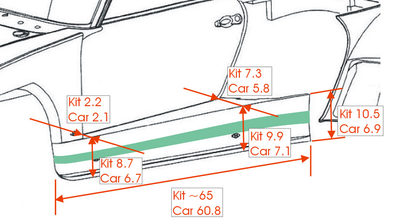
| The next request was to measure the skirt, since it seemed that a big part of the shape problems was in that area. Here are the kit and real car dimensions. The skirt length difference might be at the front, since the wheel opening is too small.
It also looks like the skirt is too wide. I'll need to study lots of photos before deciding what to do there.
|
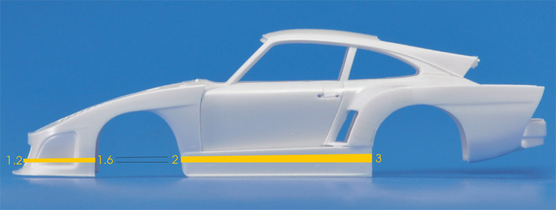
| I decided to cut out a wedge from the skirt, 2 mm at the front, 3 mm at the rear. Expanding these cuts to the front gives a 1.2 mm cut at the very front, increasing to 1.6 mm at the wheel opening.
| 
|
Body shape corrections
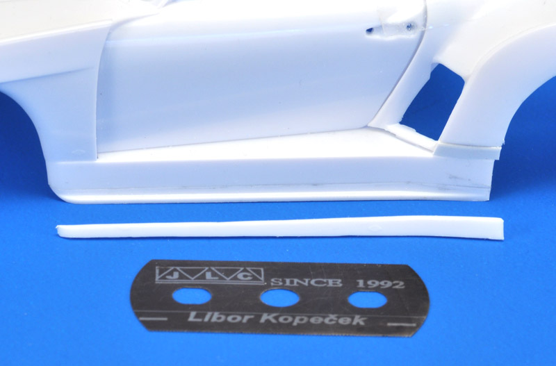
| I started with the skirt. As planned, I cut out a wedge, 2 mm at the front, 3 mm at the rear, using a JLC razor saw.
| 
|
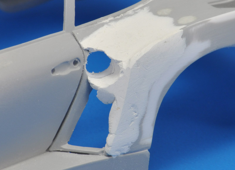
| For the nose section, I calculated that a wedge of 1.2 mm at the front, to 1.6 mm at the rear had to be removed. The job also was done with a JLC saw. I tried to find the best location for the cut through the headlight. Before the cutting, I removed the rear wall of the headlight bucket. It would need rebuilding anyway.
|
| Here the parts almost touch again. The cut worked well for the nose and the headlight, but it requires another cut to move the rear lower corner of the headlight.
| 
|
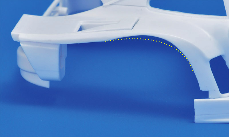
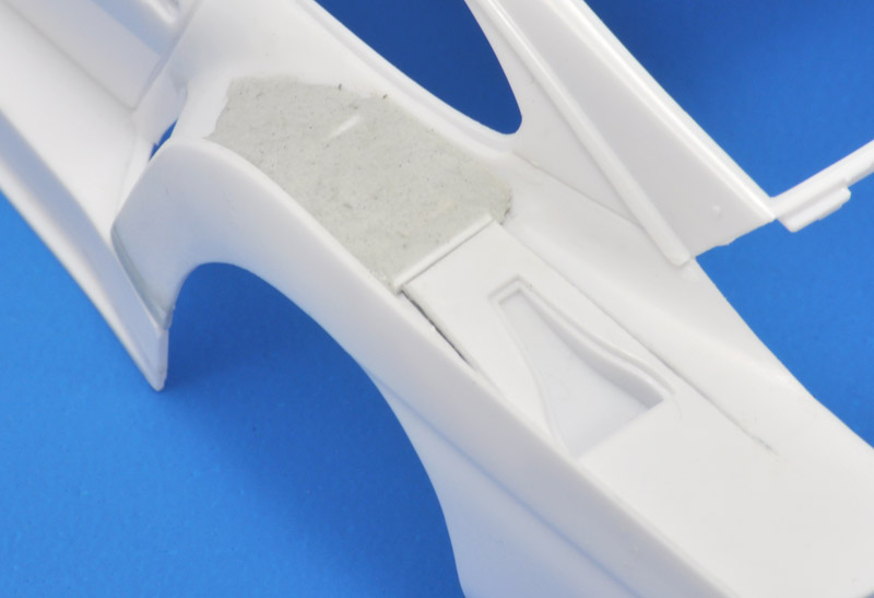
| For the rear fender, the basic solution appeared to be to move the fender side (part L2) up by 2 mm. This moved the wheel opening up. The upper side of the fender will need to be built up, elimating the small radius under the window. It will also create more of an 'S' curve in side view, as seen on the real cars.
|
| I removed most of the details on the inside of the fender side part (part L2), so I could move it freely. I raised the rear side 2 mm like the front side, making the lower edge of the fender touching the bumper (not shown in the photo).
| 
|
| Here's the line drawing over the model with the three modifications shown above. Note that the far-side rear fender had not been modified yet, so ignore that bit.
It seems that my skirt height reduction was a tad too ambitious by about 1 mm. The rest of the modifications looks good to my eye. The headlights are a bit off.
|
| Of course, more work is required. Here's my analysis of the front wheel opening. The photo analysis showed it needs a 2 mm enlargement at the top and at the rear. A 31 mm circle connects it, and I drew that on the model with a circle template.
| 
|
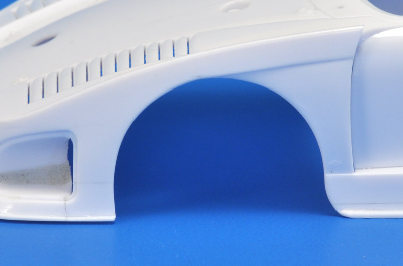
| I used a sanding drum in my motortool to enlarge the opening. As luck would have it, the bottom end of an old film container is 31 mm, and I wrapped sandpaper around it to make the modification nicely circular. The shortening of the skirt makes its length creeping up to the measured value.
The 'step' in the fender was moved upwards by first cutting a shallow slot with a JLC razor saw, then scraping and sanding to remove the excess.
Also visible is the modification of the lower rear corner of the headlight bucket. The mismatch seen five photos up was fixed by cutting off the corner, removing a slice, and reattaching it. The rear wall of the headlight bucket still has to be restored.
|
The nose required some repairs after the cuts. I used CA glue to reinforce the joints, then applied Apoxie as a filler.
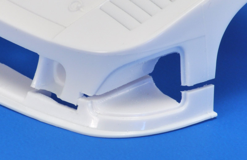
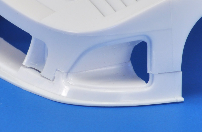
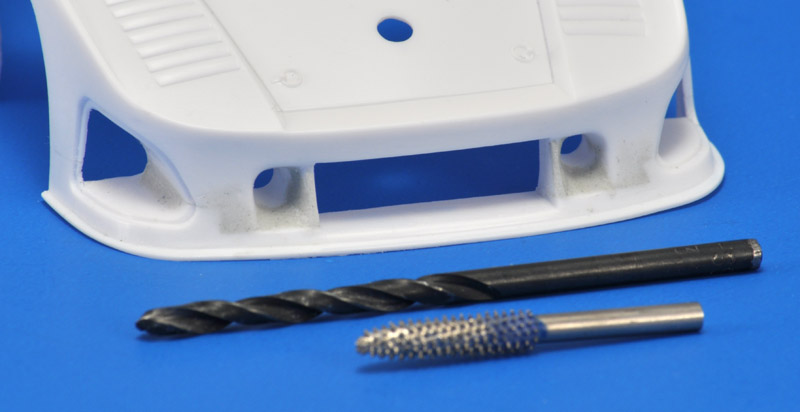
The front brake air inlets are shaped rather awkward, with a cilinder inside the tapering inlet. I enlarged the end diameter to 3.5 mm (from maybe just over 2 mm), then used my 'pineapple' grinding tool to remove the reminder of the 'cilinder', and lastly applied Apoxie putty to make smooth ducts.
| 
|
| Attaching the left upper fender (L1) required a lot of scraping, sanding and test-fitting. The right upper fender (L3), seen here, fitted a lot better.
In preparation of the slight thickening of the fender, I made three cuts around the NACA air inlet, so I could bend it slightly upwards.
Lastly, I removed plastic that could hinder the fit of the large rear wheels; part of the flanges of parts L1 and L3 was ground away.
|
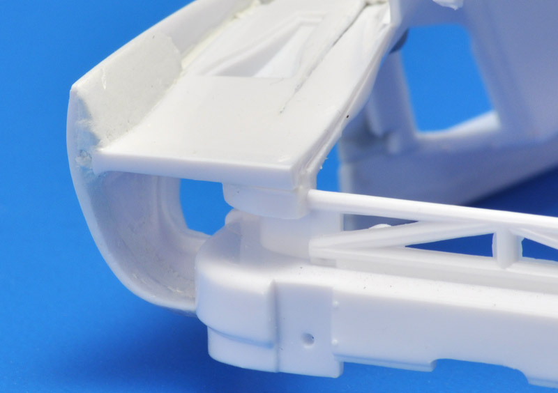
Lastly, the fender sides (L2 and L4) were attached. They had 2 mm extensions at the front, and at the rear, I wanted the lower edge to just touch the bumpers. This position resulted in the fins / strakes at 6 mm above the fender side. The new position required a lot of sanding of the outsides of the 'fender exhausts' (for the lack of a better description).
To raise the upper surface of the fender a bit, I glued several 1 x 1 mm plastic strips, then filled the remainder with Apoxie Sculpt. This is the first step, establishing a new surface, details will be done in the second round.
| 
|
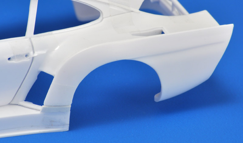
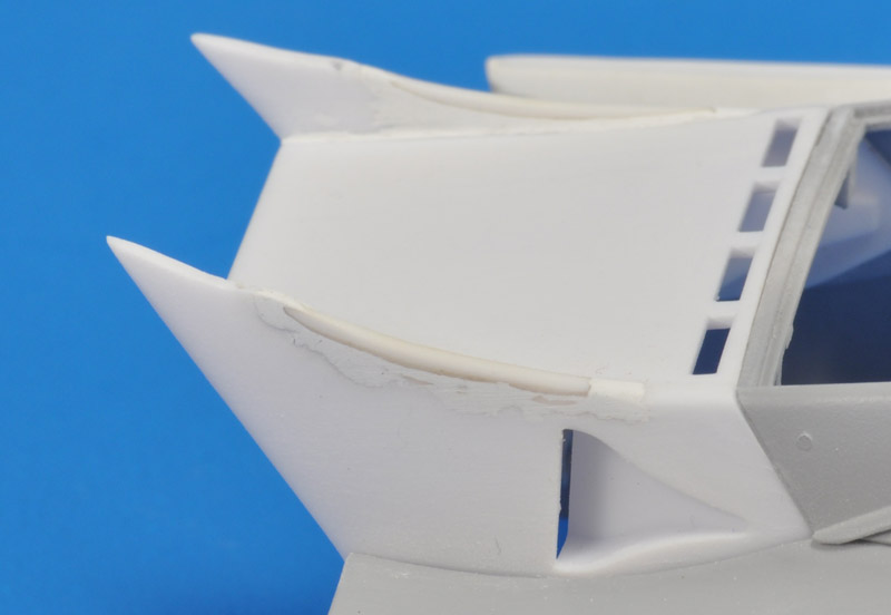
| At the back of the fenders, I built up the fins / strakes (they are quite fat at the base), and did a first round of filling the gaps in the 'fender exhausts'.
I really like how the bottoms of the fenders just touch the bumpers. That's how a real K3 looks like. The lower attachment of the Nunu model is more like a customer 935-79.
|
| After all the surgery and Apoxie, time for some Mr Surfacer (bottle) on the affected areas. I haven't finished work on the front side of the rear fenders, since I still need to pick the car that I want to portray, and they all have different inlets there.
| 
|
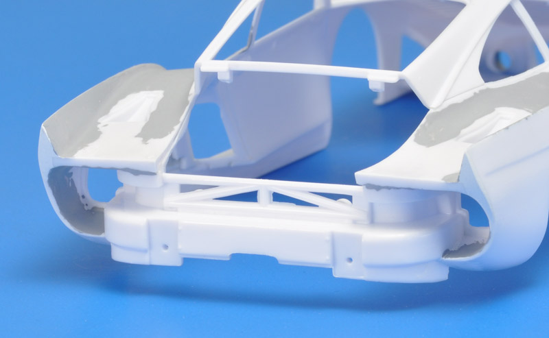
| The 'exhausts' of the rear fenders also needed some Mr Surfacer. They are difficult to work on.
|
After sanding the Mr Surfacer from a bottle, I sprayed the same areas with Tamiya Fine Surface Primer. More sanding will follow.
The rear fender inlets are still not finished, pending the choice of the car I want to portray.
| 
|
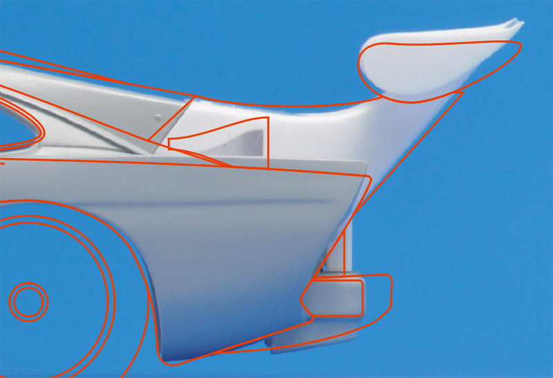
| The last major body part was the rear wing, the shape of which also had a question mark. I made a new side view photo, and it showed that the wing is positioned almost 2 mm too high, and angled up too much. I will also reduce the height of the strakes on the rear fenders, after seeing this photo analysis.
|
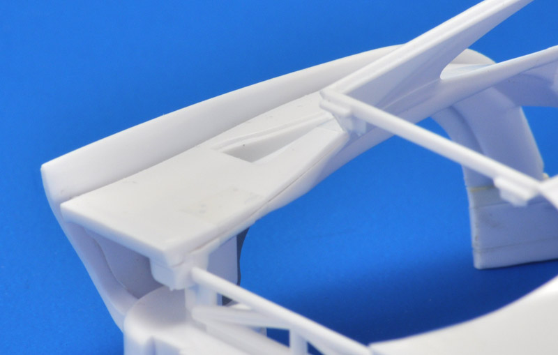
| I removed 1.3 mm at the front of the wing support, and 2 mm at the rear. Also, the forward half of the wing supports was filled in with 1.3 mm rod, suitable sanded at the ends.
| 
|
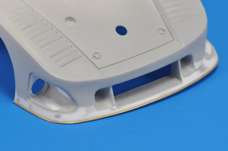
| The kit's splitter plate was much larger than what I saw in photos of 'my' K3. I removed the splitter plate by sanding from the front (not the bottom), then glued an 0.5 mm brass wire in its place.
|
The inlets on the selected real K3 were rather different than that of the kit. Here's the first stage of the modification, still very rough.
Something I hadn't noticed before: the body is twisted. Did I introduce unwanted stresses in the body during the assembly? I'll probably never know.
| 
|
Wheels and tires
| To mount the tires on the tapering wheels, they have raised 'lips' on the inside. Therefore you can mount them only one way. But the outside ends have the most flash. I tried sanding it away, but it's stubborn.
| 
|
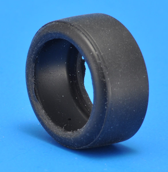
| Even worse was that I saw the tires delaminated when I sanded the flash, see the 8 o'clock position. Nasty. I might make my own tires, to avoid dealing with this.
Sorry for all the dirt specks on the tires. I blame Nunu, since I had to do so much sawing, cutting and sanding that my desk became really dirty.
|
Colors
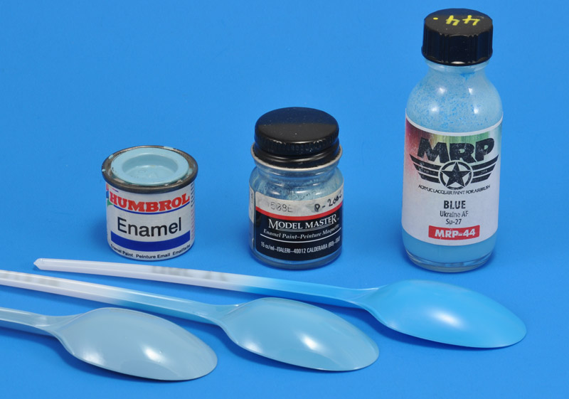
The great photos in 'Gruppe 5' show a baby blue color. In other pictures found on the net, the color varies from pale blue to baby blue to mid-blue. I decided to base my model on the 'Gruppe 5' photos. And luckily I found three model paints that came close: Humbrol 47 Sea Blue, Model Master 1508 Light Blue Gloss and MRP-44 Ukraine AF Blue.
The MRP color turned out to be a stronger blue than expected. Humbrol is paler than Model Master. Choices, choices..
| 
|
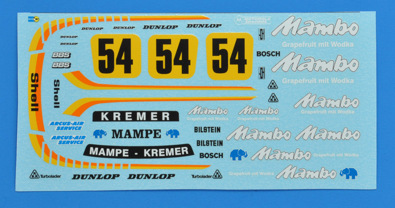
Decals
Something I hadn't considered when doing the surgery: most aftermarket decals will no longer fit my model. Another problem was that none of the K3 color and sponsor schemes appealed much to me. In the end I decided to build the first K3, that Klaus Ludwig drove to a DRM championship in 1979. I found three excellent pictures in 'Gruppe 5', pages 84 and 85. In these photos the car had white 'Mambo' markings, that were changed to black later (plus other changes).
Apart from the 'Gruppe 5' photos, I found only low-res photos of the car. But they were still useful since they offered different views of the car. Here's the set that I designed, using the K3 drawings as published in Scale Models as the sketch board. The yellow-orange striping's shape was copied from the Nunu sheet (ignoring the black part of that decal), which should give a good fit.
| 
|
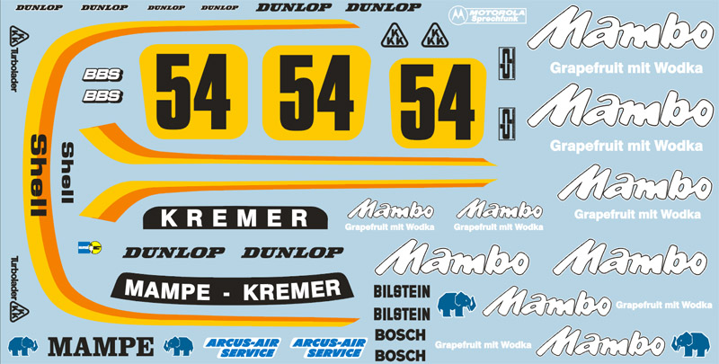
| Here are the same markings, rearranged for the print set. It took approximately six hours of work.
|
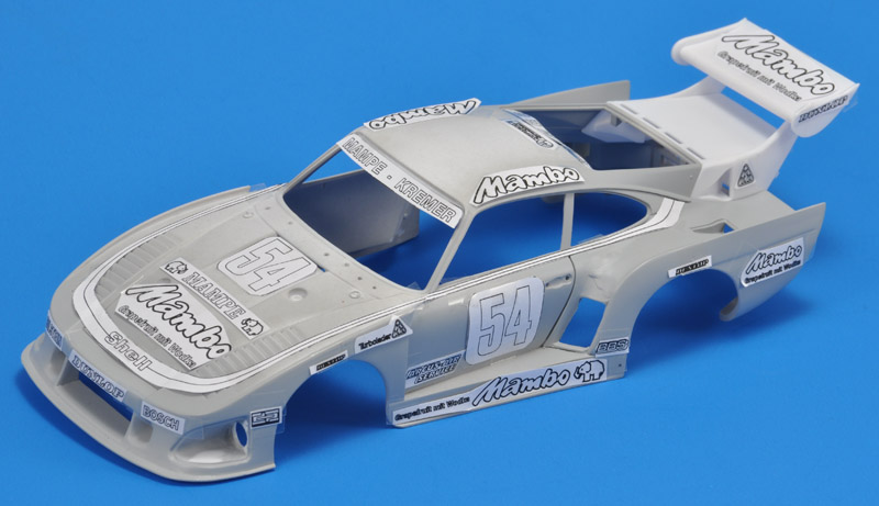
| I made a test print on paper, and fitted all markings to the body. A few problems surfaced, like the 'DP' logo behind the headlight, that was too large, and the 'Mambo' logo on the roof that also was a bit too large.
| 
|
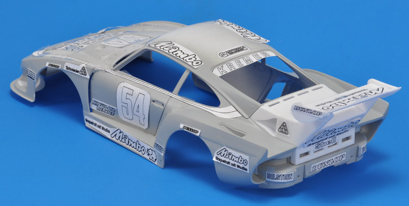
| The decals on the rear side fitted well, but the Mambo marking was a bit too large. Also, the wing looks to be positioned way too high.
|
| The yellow-orange striping on the front fenders runs over the louvers, and that is always a drama with the decals. I decided to measure the louvers, and cut up the striping decals into separate parts. Here's the measuring in progress.
| 
|
| The definitive set was off to SpotModel for printing. By now I had spent probably ten hours on the decals. Here's the printed version.
|
Various links
1979 season DRM races on YouTube:
1979 DRM season
| Race #
| Date
| Track
| Base color
| Markings
|
| 1
| 11 March
| Zolder
| White
| Numero Reserve / Philippe Salvet
|
| 2
| 8 April
| Hockenheim
| White
| Arcus Air Service
|
| 3
| 29 April
| Nürburgring
| White
| Saturn / Hansa Foto
|
| 4
| 20 May
| Salzburgring
| ?
| ?
|
| 5
| 17 June
| Mainz-Finthen
| ?
| Masterfoto
|
| 6
| 24 June
| Norisring
| White
| Arcus Air Service. Two K3s entered, second one with Minolta markings
|
| 7
| 1 July
| Zandvoort
| ?
| ?
|
| 8
| 22 July
| Diepholz
| ?
| probably first with Mambo. Mambo in white, no yellow area under race number?
|
| 9
| 19 August
| Zolder
| Light blue
| black Mambo markings
|
| 10
| 2 September
| Hockenheim
| Light blue
| black Mambo markings
|
| 11
| 23 September
| Nürburgring
| Light blue
| black Mambo markings
|
Intercooler installation on Porsche 935 K3/81, chassis 01 00020
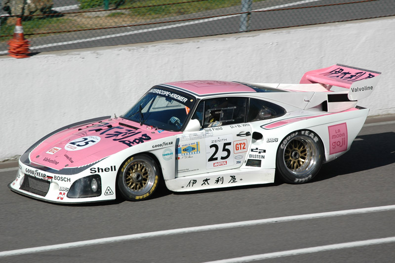
The air-air intercooler was one of the strong points of the K3, lowering the air temperature from 70-80 °C to 35-40 °C according to Klaus Ludwig. But references are rather unclear about the actual installation. But my many visits to the Spa Classic answered that question.
Here's a 1981 K3 at the 2014 Spa Classic. The owner/driver was listed as Nicolas D'Ieteren. Racing Sportscars entry for the 1981 Le Mans race lists the car as chassis number 01 00020 with start number 59.
| 
|
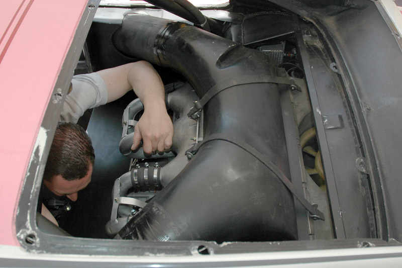
| I was lucky to catch the crew working on the intercooler, with the sheet metal off. That's one massive air duct there! Also, note the engine fan, to give an idea of the intercooler's position relative to the engine block. Also of note is the frame for the original rear window.
|
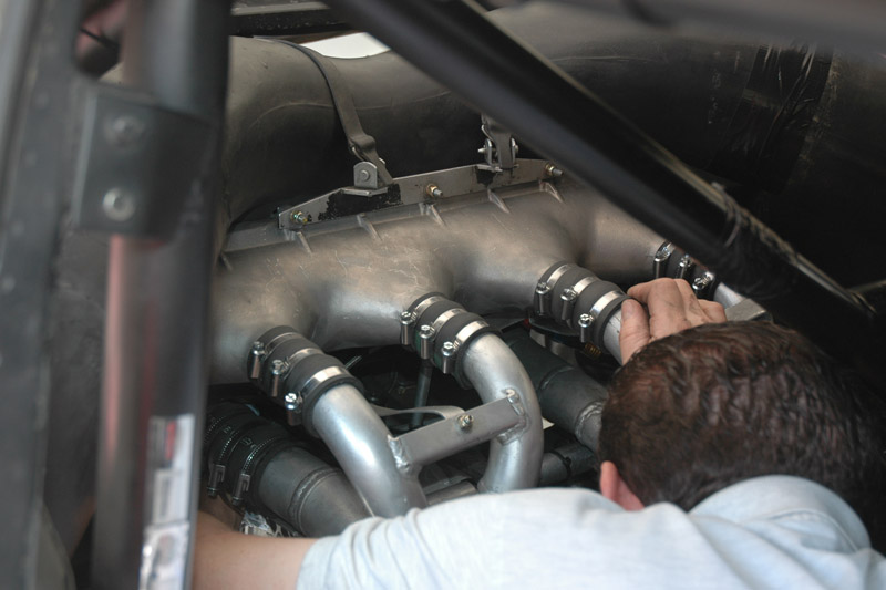
| The front view shows how to two large-diameter pipes coming from the two turbos split up in two smaller pipes each, which then feeds into the intercooler. This resembles the set-up of the 908/03 I think.
| 
|
Return to models page