Revell 1/96 Apollo Lunar Module


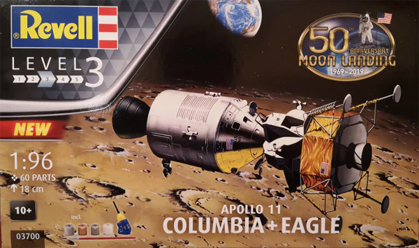
For the 2019 IPMS-NL Euro Scale Modeling show, our club (IPMS-NL Regio Zuid-Holland) decided to build a '50 years Apollo 11' stand. It would display six stages of the mission, all in 1/96 scale. I picked the stage where the CSM plus LM circled the moon. This page describes the construction and painting of the Revell 1/96 Apollo Lunar Module.


Kit description

There is no resin replacement for the Lunar Module (LM), so building the Revell original was the only route. I guess it predates the actual Apollo 11 mission, so it's missing a number of details, and probably some details are not correct. I can't give you all details, since this build was done in a hurry, and prevented me from doing much research.

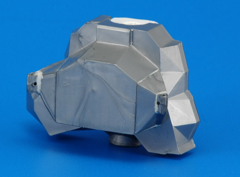
My first comment on the Ascent Module would be that I'm not sure that the overall shape is correct. Although I did not study it in detail, I think the facets are not all correct. Given the short time to build the model, it was not an option for me to modify these facets. I did however improve some other details of the model. I really liked the effect of the improved resin RCS nozzles on the model. Especially those of the Ascent Module are pretty ugly, basically just cylinders.

For the Descent Module, I can point out a few things. One is the descent rocket motor nozzle on the bottom side, that is molded only partially, and also lacks the large cavity in which it can gimbal. The thrust deflectors for the RCS nozzles of the Ascent Module are also missing. They were probably far too delicate to mold, if Revell had wished to include them.


LM Ascent Stage construction

Work on the Revell Lunar Module started with a shock: rough parts, lots of flash, vague fit and unknown accuracy. I was very happy to find the SMOKIN II: The Airfix LM page on the Ninfinger site. It included the excellent David Weeks drawing and lots of color information. I used these drawings extensively.

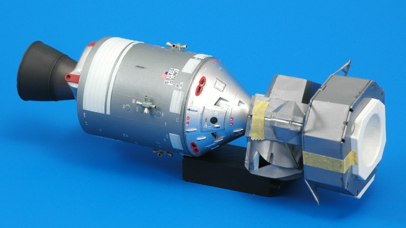
First thing I changed was the connection to the CSM: I used a Dremel sanding drum to give the LM tunnel the same size as the CM tunnel, so it would connect properly to the RealSpace CSM. I glued a square of plastic card behind the opening, with two stacked 5x2 mm magnets. The latter was overkill, the magnetic force was almost too much, slamming the models together when trying to connect them carefully.
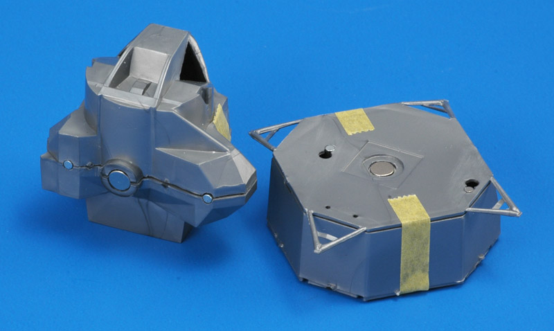
For the connection between the Descent Stage and the Ascent Stage I also used magnets: a 5x2 mm fitted inside the Ascent Stage's 'rocket engine', and 2x2 mm magnets where Revell model originally had locking pins. Plus of course matching magnets in the Lander. The Ascender rocket had to be scraped off a bit, otherwise the Ascender would wobble on the Lander. It turned out to work well, very practical when building the models separately.
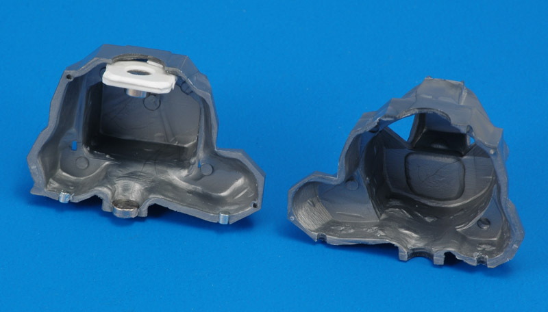
Here's an overview of all magnets installed in one half of the Ascent Stage. If you look closely you can see small shims around plastic plate that holds the upper magnets, that were required because of the unevenness of the plastic on the inside of the Lunar Module - typical of sixties models. Later this connection was reinforced with Apoxie to prevent things from coming off after assembly.
The real Ascent Stage is really complicated, and it took me a while to see what needed to be done with the model. I started with one obvious error, the lack of 'eyebrows' over the triangular landing windows. I added Apoxie Sculpt to build them up. The Apoxie still needs to be cut and sanded down to the real shape - I built it up way too thick. Interestingly the 1/100 Revell model does have the 'eyebrows', see Revell 1:100 Apollo: Lunar Module "Eagle" (04832). This proves that this is a different model / mold!

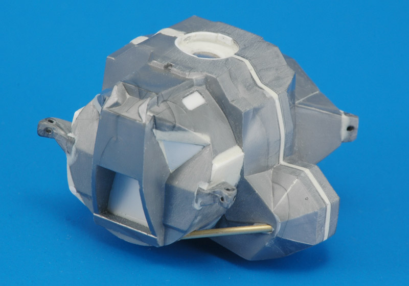
The second modification is the removal of a triangular piece, that is a cylindrical strut in reality. I used a JLC saw, and filled the resulting hole with more Apoxie. New holes were drilled and a piece of 1.3 mm plastic rod was installed. Note that the installation required multiple applications of Apoxie Sculpt, and thus took quite a bit of time. I made the strut removable for painting purposes, and later replaced it with a piece of Albion micro tubing.
Fellow club member Hans found out that the Ascent Stage needs a 1 mm shim between the halves, based on the David Weeks drawing.
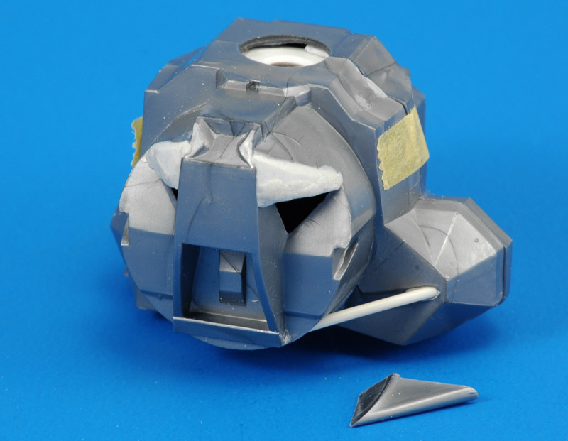
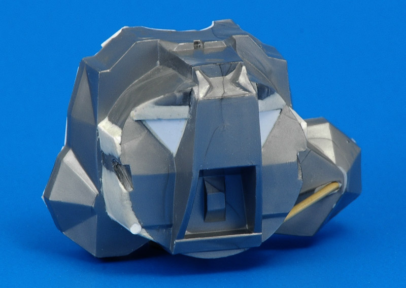
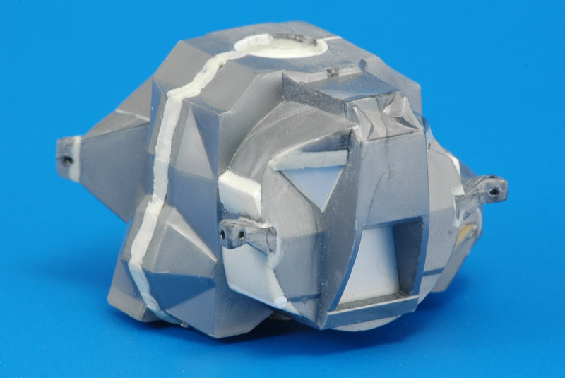
On the front side I made three 'bulges' on the circular part that surrounds the moonwalking hatch. Again I followed the David Weeks drawing. In the 2 and 10 o'clock positions I glued a triangular plastic strip of 0.8 x 0.8 mm, in the 8 o'clock position a 1.5 mm plastic rod, and then built up the bulges with Apoxie. At this point I also mounted the 'windows' from the inside. For our club project we had decided to use black windows, so I used normal white plastic card to create the windows.
On the rear side I first added pieces 30 and 31, the extensions for the RCS thrusters. A little Apoxie was used to fill gaps. Next were the RCS thruster sets (parts 32). Like on the CSM, the plan was to replace the thrusters. For that purpose, I drilled hole straight through the fuggly Revell thrusters into the block, to end up with four holes in each block. The remains of the thrusters were then cut off, and the blocks glued on the LM. Now I could sand the very rough shapes to something resembling the real things. Time was getting tight and I could not go overboard with reconstruction. Apoxie was again used to fill gaps and smoothen transitions.
Next on the front side were the RCS thruster sets. Part 36 goes on the left side, part 37 on the right side in the picture. I used the same recipe as on the rear side: drilling through the thrusters to create holes in the block, where I would install resin cast thrusters.

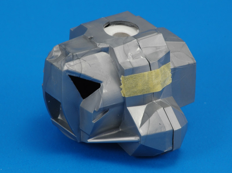
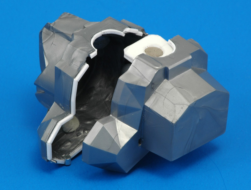
The two halves of the Ascent Stage were glued together, and a worm of Apoxie was placed over the gap caused by the widening.
In this photo the Apoxie over the glue joint was cut and sanded down. Also visible are an extra docking window (closed with plastic card) and a new moonwalking hatch - replacing it was easier than trying to scribe inside the cavity.
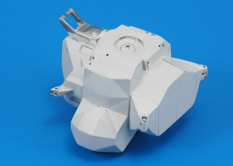
I painted the model with Mr Paint primer, to check for small build defects, that were repaired with Mr Surfacer 500 from a bottle. I needed two rounds of checks and corrections before I was happy. Due to severe time constraints I did not check the model on shape problems, that are very likely present, since the model was designed before the moon landing.
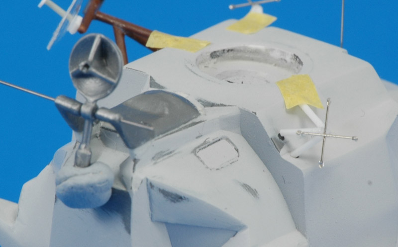
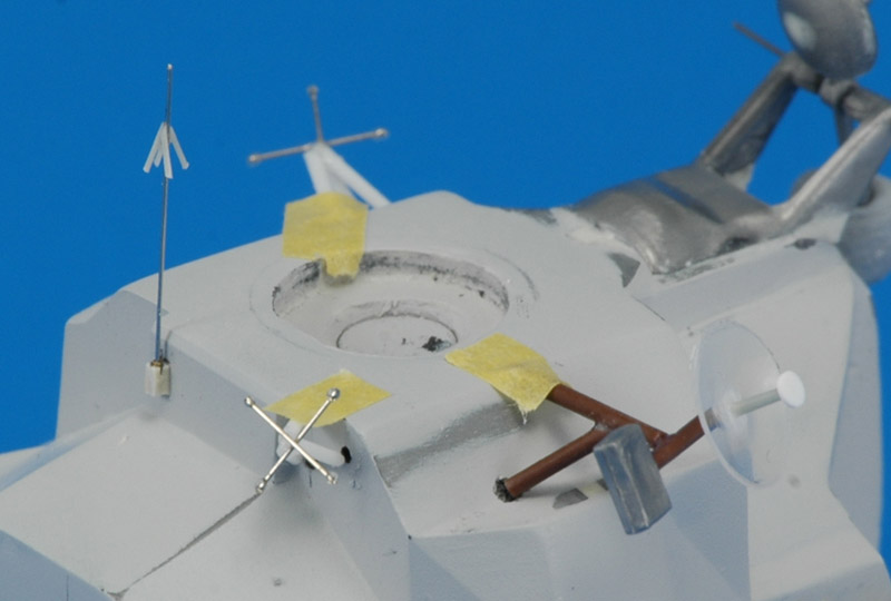
With most of the Ascent Stage body done, work started on the various antennas. On the left the 'Rendevouz Radar Antenna' and its mount, with a 0.3 mm steel wire drilled through to make it posable. Revell's parabolic antenna had a moulding ridge at most of its circumference, so more Apoxie was added. On the right one of two VHF antennas, that Revell did not include. It consists of a 'tripod' of 0.5 mm plastic rod with two 0.2 mm steel wires as the antenna. On each of four ends is a droplet of epoxy glue.
Three more antennas, both approximations of the real things since the scale did not allow much more. Left is the 'EVA antenne', built from 0.2 mm nickelsteel wire with 0.2 mm stretched sprue 'harpoon hooks'. The real antenne probably had more than the four that I had the patience for. In the middle the second VHF antenna, built the same way as the first.

Right the 'Steerable S-band antenna'. Revell's version was flat instead of a pyramid tripod. Therefore I built a new one from 0.7 mm plastic rod, using the dimensions from the David Weeks drawing. The parabolic antenna by Revell was 5.5 mm diameter, but the drawing showed 7.0 mm. Therefore I thermoformed a new one, and reused the Revell box part.
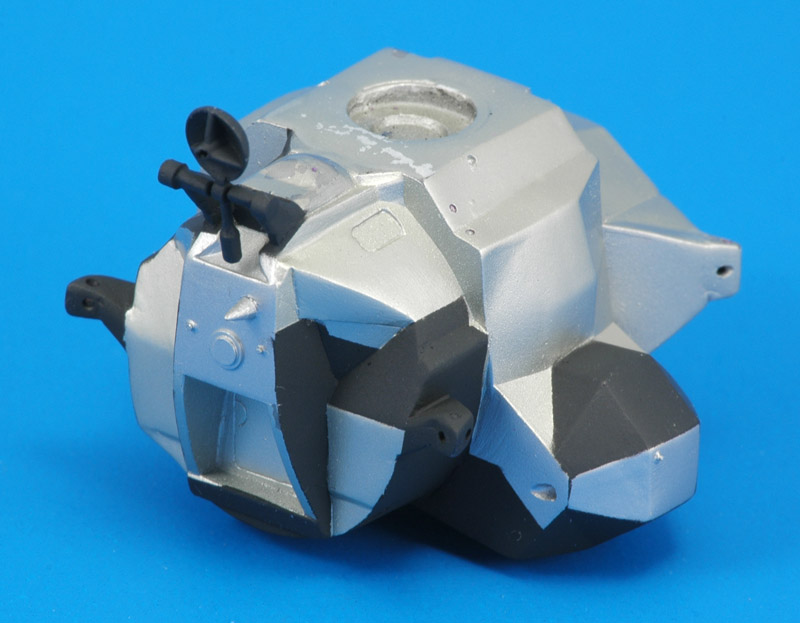
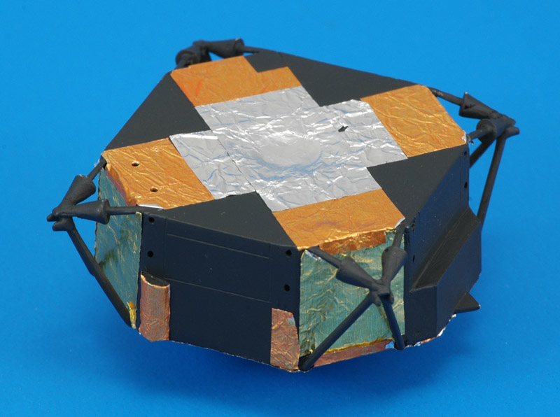
Time to apply the definitive colors. The main color was mixed from 1.8 ml MRP-128 Silver with two drops each of MRP-122 Yellow and MRP-26 Russian Green. The next color was straight MRP-128 Silver on selected areas. It is hardly visible, a lot of work with little result. The third color was Revell 9 coal black, applied in two stages due to the complex masking. You see the first stage here, the front side. Tons of masking, actually it wasn't funny anymore. Plus, I ripped off some paint, like on the top.

Other new details first seen here are five docking lights all over the body, made with pieces of 0.5 mm stretched sprue in 0.5 mm holes. I forgot to paint them though. Also new is circular tracking light above the moonwalking hatch, built up from 3.0 and 2.3 mm circular Waldron discs, punched from 0.3 mm sheet. Lastly there are two cone-shaped 'S-band in-flight' antennas, one on the front and one om the rear. They were made from a piece of stretched sprue.
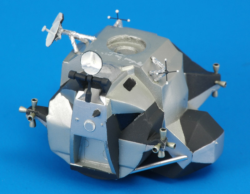
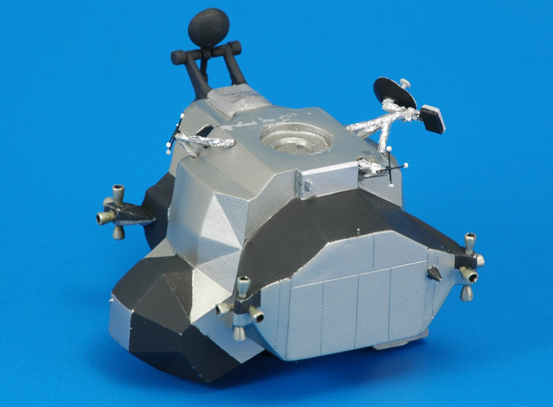
Final assembly consisted of adding sixteen prepainted resin RCS thrusters (as shown on the RealSpace 1/96 Apollo Command & Service Module page), followed by three antennas, now wrapped in aluminum kitchen foil. I left off the 'EVA antenne' since it conflicted with the CSM once coupled. Windows were represented with black decals. The strut on the right side was wrapped in BMF foil.
The rear side shows basically the same details. I'm not totally happy with the result, but there was no more time to improve things.


LM Descent Stage construction

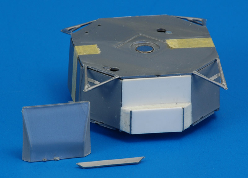
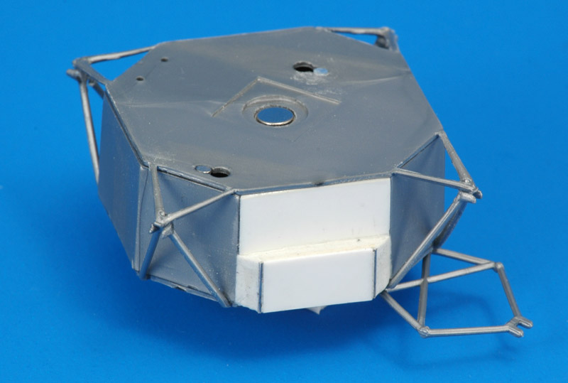
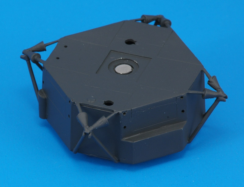
The octagonal Descent Stage has one facet that extends outward. I cut it out and replaced it with a 'standard' flat panel. Next a box structure was added at the bottom of the new panel, 2.5 mm thick and 7 mm tall. Only then I understood what Revell did here to represent the correct shape. The sides of the Descent Stage have a draft angle to facilitate injection molding, that the real thing of course did not have. I decided not to correct this problem.
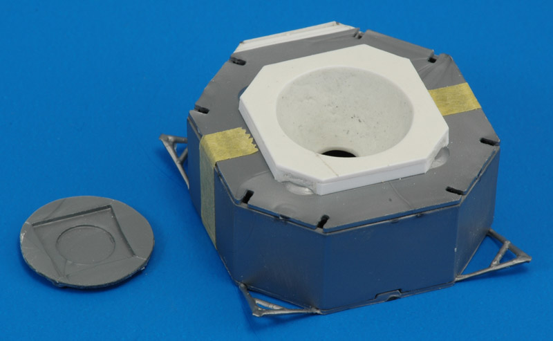
The lower side lacks a 'flat box' around the descent nozzle. I measured a 27.5 mm square in the David Weeks drawing, with 3.5 mm cut off each corner, that I cut from 1 mm plastic card. I added 2x1 mm strips around the long sides to make a 3 mm tall box. I left the short sides open, and that was a fortunate choice, since that allowed the box to sit on top of the four shallow domes on the Revell part. In the center I cut out a 20.5 mm circle.

The interior for the nozzle was a bit of imagineering. I cut a similar 20.5 mm circle in the Revell part, and glued in a 7 mm wide strip rolled to a tube. The short tube was closed with the circle that I cut from the 'flat box' piece. The closing piece got a 6 mm hole, a bit of a random size chosen to attach the nozzle to. Apoxie was added to the inside to create a bell-shape, using a piece of plastic card, cut to a curved shape, as a scraper. I've read that the rocket nozzle had a 6 degree gimbal freedom in all directions.
Revell provides a partial nozzle, shown on the right. I wanted a full nozzle, so I made a master from a spinner (green) and a 15 mm cowling (white) from the spares box, shown in the middle. Apoxie was added to make a smooth shape. Next a piece was vacformed, shown left.

The vacformed piece was paper-thin, as you can see. Later I wrapped it completely with 0.5 plastic rod, using CA-glue. After gluing I scraped off roughly half of the rod thickness again, to eliminate the 'ribbing'. This finally gave me a workable new nozzle.
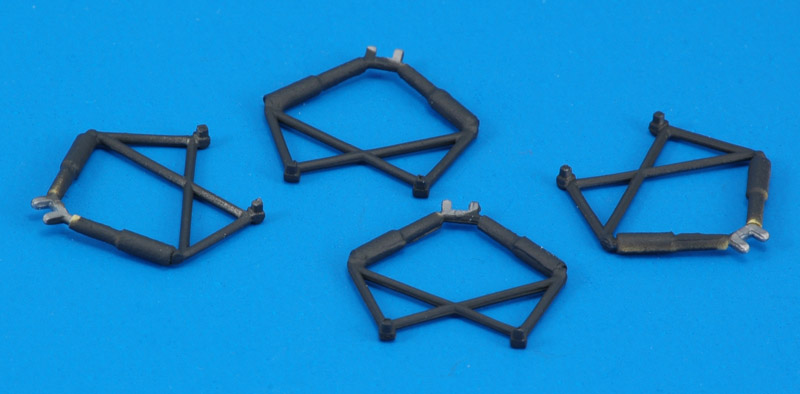
Assembly started by gluing the box together, consisting of top and bottom plates and the octagonal walls in between. Next I carefully fitted the V-shaped struts that attached to the bottom plate. Together with the V-shaped struts attached to the top plate, they created four sturdy pyramids. Also I dry-fitted a lower wishbone to one corner.
I used Apoxie filler for the 'long' sides to smooth the glue joints between the top and bottom plates and the sides. I skipped that step on the 'short' sides, saving work, since they would be foiled anyway. I also engraved three hatches, added a half-cylinder, and engraved the lines on the top side that would help with the foiling.

To create the cone shapes on the upper struts, I glued on 3 mm plastic card discs with a center hole, and used Apoxie to build up the cone shape. The whole assembly was painted with Revell 9 coal black.
At this point time was getting tight, and I stopped looking too much at photos of the real thing. The David Weeks drawings showed larger-diameter tubes on the lower wishbones, and I built those up with Tamiya tape to achieve 3.0 and 1.5 mm diameters. Not a really nice solution, but a quick one. You can still see the yellow tape on some parts. Later I painted the part of the tubes Humbrol 11 Silver.
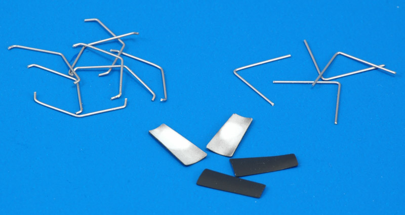
More stress when I noted that I still had to build the deflectors for the RCS thrusters. But I found out that only two wire shapes were required, so I could use series production methods. The eight 'flat Vs' and the four 'Vs' were bent from 0.5 mm brass wire, and painted with Mr Paint Silver.

The length of the blast deflector plates was taken from the position of the RCS thrusters on the Ascent Stage. They were cut from 0.3 mm plastic card, curved around a stick. The photo shows the back sides painted; the front sides are still to be painted.
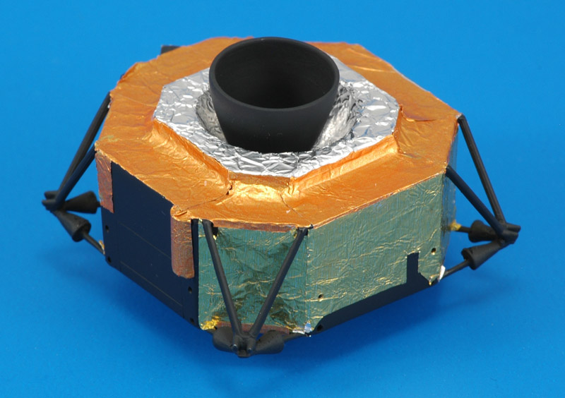
The day before the show I started with the foiling. I had kitchen aluminum foil and a nicely wrinkled gold-colored sheet. To make dark-gold foil, I lightly overcoated the gold-colored sheet with Mr Paint Signal Red. The foil was applied according to the David Weeks drawings. I painted the vacform nozzle with Revell 9 coal black, and lacked the time to paint it again according to the drawings.
The top side was also foiled according to the drawings. I used CA glue, and this was a hit and miss method. If you look closely you can see many unglued foil edges, and that problem kept popping up. And I kept gluing them down.
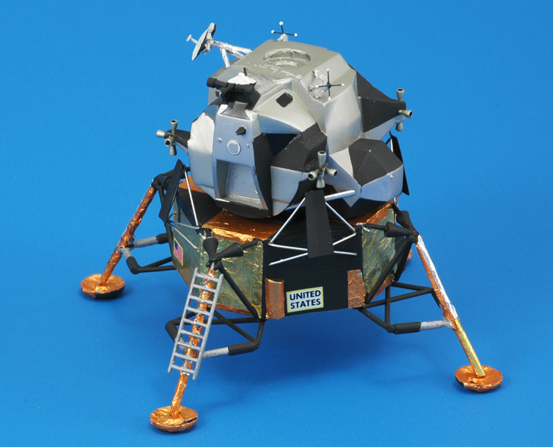
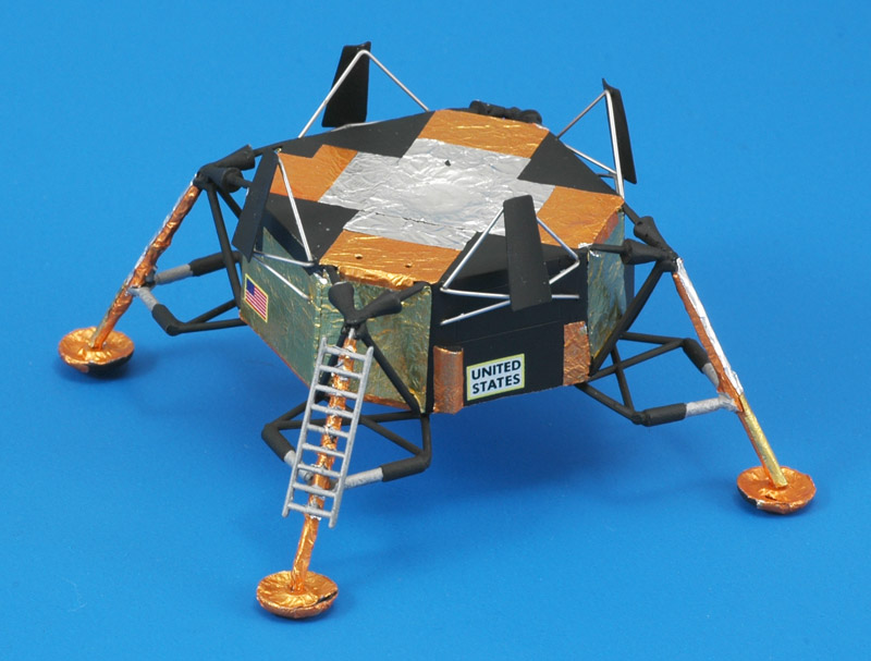
Fast forward to the end of the last day, with the legs and thrust deflectors added. I do not know how accurate these leg parts are, I just slapped the Revell parts together! The only real modification that I did was to improve the landing leg with the ladder. That one was moulded in a D-shape with the flat side towards the ladder, and I carefully carved away the excess. The two decals were of my own design, custom-printed by Spotmodel.

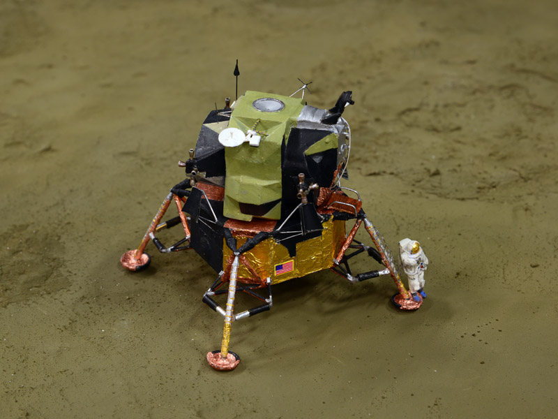
For a long time, I did not know whether the Lunar Module legs should be folded or extended for the flight phase that I'm depicting. I finally found the answer on the CollectSpace forum: on Apollo 11 the gear was deployed at 098:14:35; undocking followed at 100:12:00, almost 2 hours later. Therefore I could do both configurations. Out of necessity, due to severe time constraints, I opted to use the extended legs.
And here are the Ascent and Descent Stages combined. Still to be added are the probes under three of four feet. After that, time was up - it was 23:00 the day before the show, and nine hours before departure.

Later I noted I had forgotten the small platform in front of the moonwalking hatch, and the landing radar on the bottom on the Descent Module. To be added later.


CSM plus LM combination

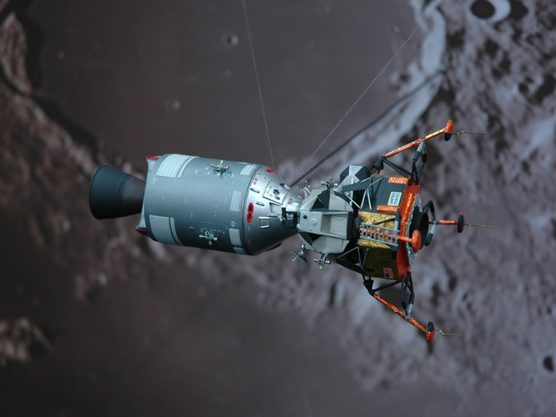
A preliminary view of the CSM mated to the LM, which is the flight phase that my contribution to the club build represents. They connect with a 60 +/-10 degrees rotation from their respective Z-axis - in other words the moonwalking hatch of the LM is 60 degrees rotated compared to the entry hatch of the CM. As shown above, the CSM and LM connect with magnets on my model.

More photos will follow.


Our Apollo 11 display at Euro Scale Modeling 2019

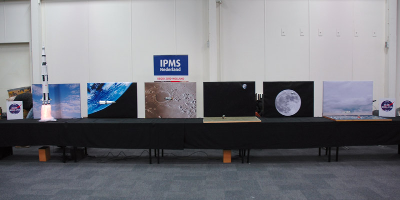
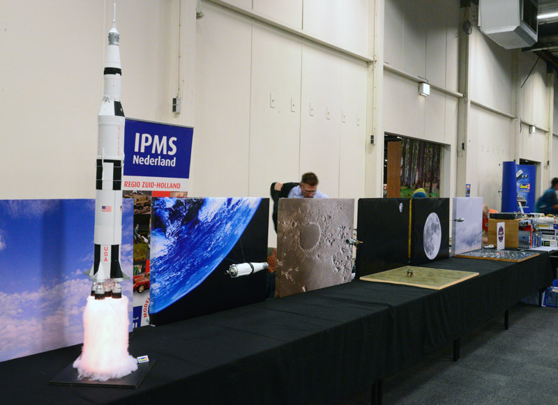
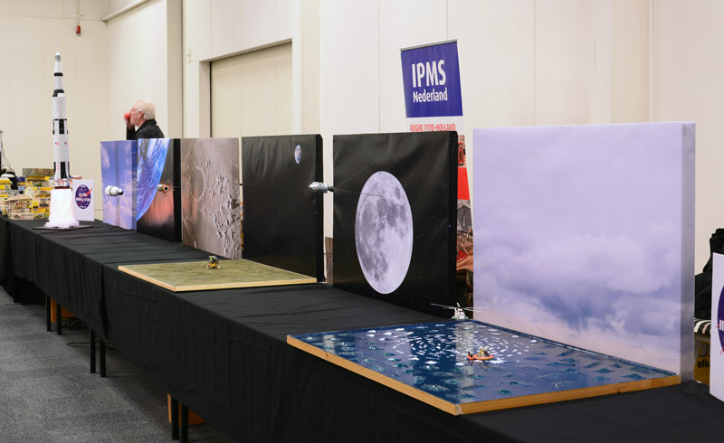
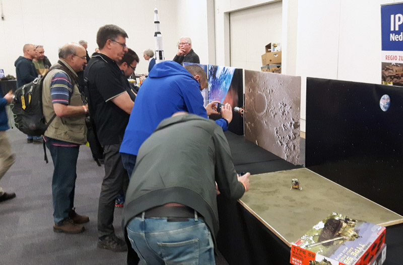
First an overview of the 'Regio Zuid-Holland' stand, before the Euro Scale Modeling 2019 show opened. It shows the six stages of the moon flight that we depicted with models. All models are in 1/96 scale, each with a background panel. It was a bit of a gamble whether we could fill a eight meter stand with just seven models, but I think it worked! Total costs were close to 300 euros, on the edge of what a club of our size can bear.
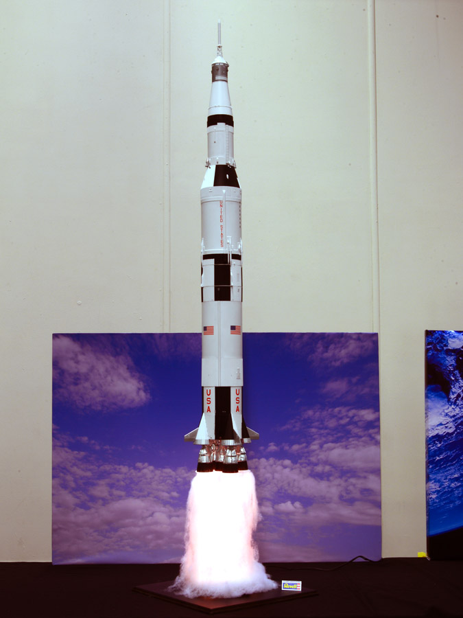
Left-side view of the stand, starting with the imposing Revell 1/96 Saturn V on a lighted column of smoke. (Photo by Jan de Wit)
Right-side view of the stand, which was the first view of most visitors, because of the traffic patterns in the halls. This was a bit unfortunate, since they walked against the timeline. I can only hope they realised what we tried to show. (Photo by Jan de Wit)
The Revell 1/96 Saturn V was built by Jan de Wit. Of course the it was way taller than the background panel, but that emphasized the massive size of the rocket. This model was kindly sponsored by the Revell importer of the Netherlands.
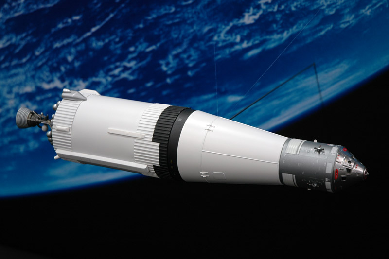
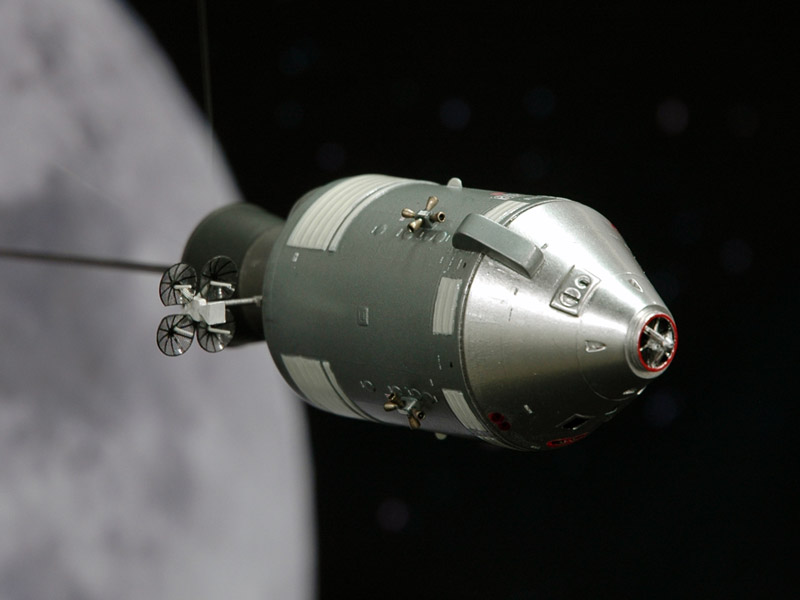
Nick van der Windt built the third stage with CSM, during translunar injection. The model is a combination of the Revell Saturn V's third stage plus a RealSpace CSM.
Here's my finished model orbiting the moon, just before undocking of the LM, that has already unfolded its landing gear. Like the model shown above, it photographed nicely against the background. Unfortunately my sweet parabolic antennas (see CSM build report) were hidden by this view.
Hans van Gelder built the model for the fourth stage, using Revell's trusty old 1/96 Lunar Module, with a lot of modifications. As you can see he recreated the moment Neil Armstrong stepped on the moon.
Reinhold Bogaard built another RealSpace CSM to depict the return flight from the moon. He used the other set of parabolic antennas shown in the CSM build report above.
Chris van Ravesteijn used a Tamiya 1/100 Sea King to depict the sea recovery of the Apollo 11 crew. I redrew the yellowed decals and had them printed by Spotmodel.
Our six-man team really enjoyed this sight that went on all day long: lots of visitors taking photos of the models. It made up for all the hard and sometimes frustrating work. And at the end of the long day we received the prize for 'Best group display'! (Photo by Reinhold Bogaard)


Links


Return to models page