Scratchbuilt 1/10 scale Locost chassis


Ever since doing a design exercise involving a truss-frame aircraft fuselage, I have a deep interest in frame structures. I'm especially fascinated with three-dimensional truss structures for car chassis design. Most car chassis are 'space frames' which are usually two flat truss sides connected with a collection of of transverse tubes. If they are designed badly, they will have a low torsional stiffness, which will make for less than desirable road holding. As an example, a Lotus Seven has a torsional stiffness of around 1,000-2,000 Nm per degree. For modern high-performance cars, 30,000 Nm per degree is the target. My own car reportedly achieves 22,000. To get a taste of classic tubular chassis design, I decided to build a Locost chassis in plastic, using the Ron Champion book.


Reference

Ron Champion published his book in 1996. I bought the 2004 edition, which is slightly revised. The book outlines how to build your own Lotus / Caterham / Westfield Seven clone from scratch, using a Ford Escort Mk2 as parts donor. It explains most but not all of the process, but nevertheless it's very inspiring. Getting a homebuilt car registered in the Netherlands is very difficult, so I never intended to build one full scale. Instead I decided to build the chassis in 1 to 10 scale. The scale was chosen for convenience: while working from the plans, I would just need to move the decimal one place. It didn't have to fit in any collection of a fixed scale, so that was another excuse for this non-standard scale.  


Construction

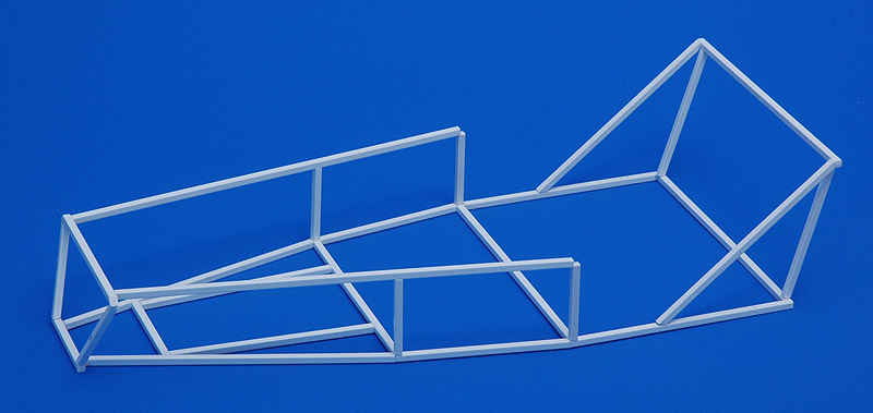
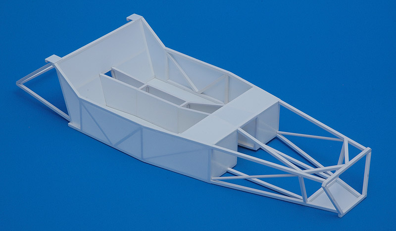
I bought four meters of 2.5 mm square plastic rod, one meter of 2.0 mm square plastic rod, and one meter of 2 mm plastic round rod. Using the drawings and instructions in Ron Champion's book, I went to work. I built the lower side of the frame on the drawing of page 47, scanned, scaled to 1 to 10, and then printed. Generally I managed to build the chassis within 0.1-0.2 mm, using calipers extensively. CA glue was used throughout, allowing for fast bonding. I used various improvised tools to jig the parts, like Lego blocks, steel blocks and plastic card. Shown here is the chassis about 30% done. After getting to the roughly 40% point, I took a break to judge the results so far. I used a JLC saw to cut some connections, and realign some tubes to square the chassis.  
I followed the book's building sequence to the letter, and at this point of construction I ran into problems. It seems the dimensions of the rear section are not correct. Turns out that that the drawings and photos do not agree, and leave you in the dark what is correct. Quite annoying!
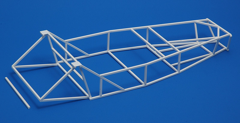
Ignoring the problems on the rear side, I continued with the transmission tunnel, built from 2.0 mm square rod, again following the book. The keen observer will spot that the tunnel is not symmetrical at the front and rear, since it was specifically designed to accomodate the Ford Escort Mark 2 drive train. Concluding the construction of the space frame were six diagonals in the sides. Build time so far was in the order of 12 hours.

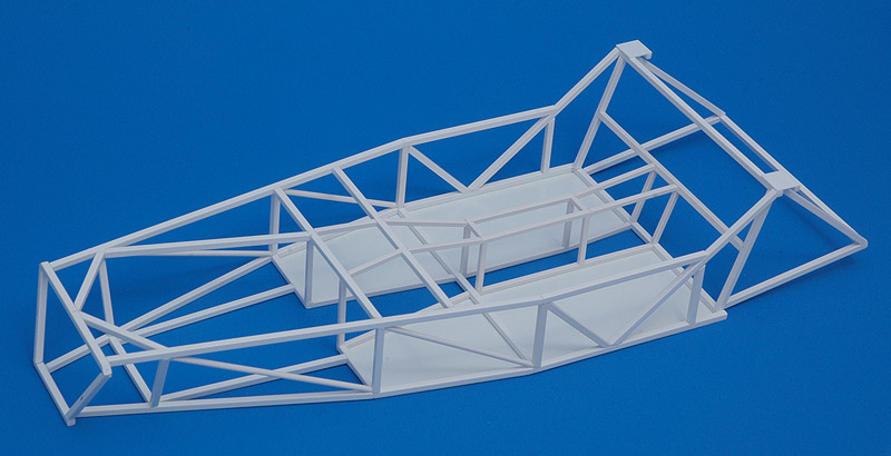
Next were the skins, and I started with those at the bottom of the passenger compartment. I used Tamiya's Ultra Thin glue to bond 0.1 mm plastic card to the tubes. I wanted to imitate some of the floppiness of the sheet metal, hence this thin gauge. It definitely has the right effect, but it's also very vulnerable, and I had to install repair patches in a few locations after breaking the skins.
 
Next the 'sheet metal' of the transmission tunnel, the rear uprights, the footwell front, the sides of the car, the top of the footwell, and the nose bottom panel were added, in that order. The last part of skinning that I added was the rear bulkhead, despite the rear end still being unfinished.
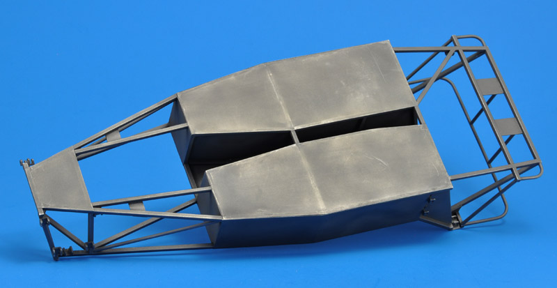
With help from fellow GPMA-member Allen James, I decided how to build the rear part of the car. For readers with Ron Champion's book: the largest change I made was making tube V 34" / 864 mm instead of 38" / 965 mm, subsequently rotating tubes RU1 and RU2 inwards, and attaching tubes W1 and W2 inboard of the spring/shock absorber mounting plates. An evening of work finished the chassis. I estimate that I spent some 20 hours on it. As you can see, I had started base-coating the model too, using Humbrol 127, in search of building defects.

After having some doubts, I decided to add the suspension attachment brackets. I used 5 x 5 mm square tube, with one wall cut away. Making 17 of them was a tedious job, no fun at all. And I found out that the instructions for the longitudinal position of the front suspension brackets is completely missing in the book, which must play havoc with the castor angles of the real thing - unbelievable! The Chris Gibbs book deals with this a lot better.


Painting

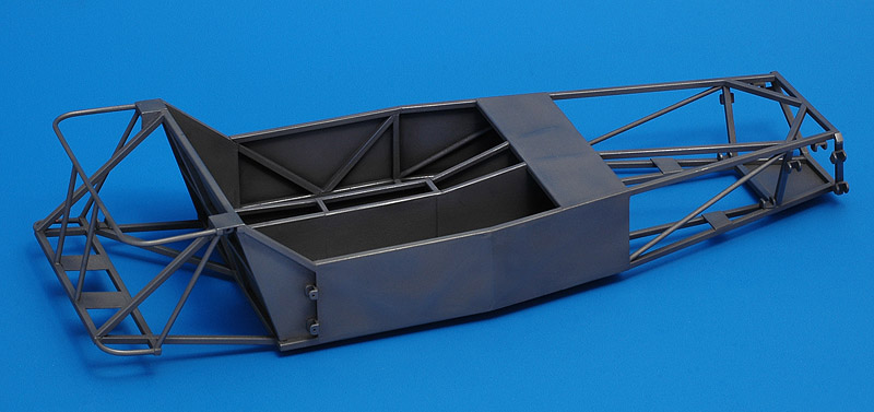
I liked the chassis in bare white plastic, but I thought it would look even better in Humbrol's Polished Steel. I used an old tin that had thickened and needed thinning, and a fresh tin that was really thin. And they behaved very different, the latter drying very, very fast at summer temperatures. Even cleaning the airbrush was almost too long a delay! Therefore the buffing did not go easy, and especially on the delicate 0.1 mm skins this was very inconvenient.

Also, I shouldn't have base-coated the model in grey paint, since its roughness showed, especially inside the passenger compartment, where the overspray settled down as dust particles. On the other hand, the buffed paint looked really nice, blotchy in appearance with shiny edges, just like steel before it rusts.


Photos

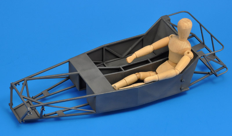
I bought a wooden pose puppet of 20 cm height, and cut one centimeter from the upper and lower legs to create a 1 to 10 scale 180 cm tall figure. He fits nicely in the chassis.  
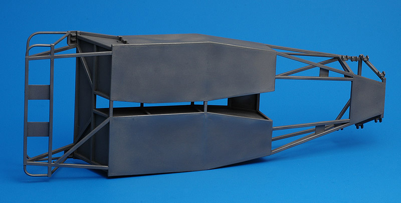
Another view of the lower side. The Polished Steel paint has weathered nicely from playing with the model.
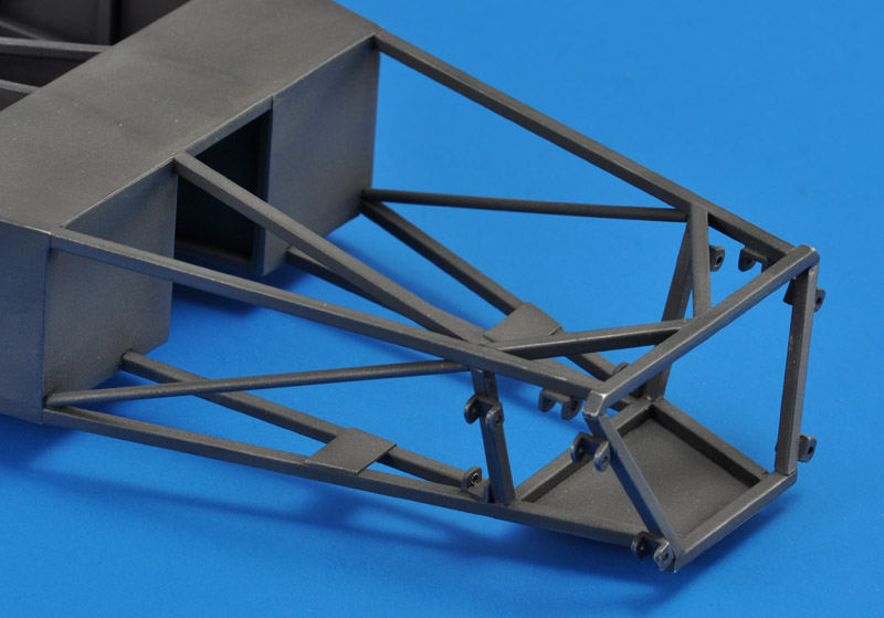
Close-up of the front side of the chassis, the engine bay. Nearly everyone comments that I forgot a tube on the left top side, but the original design lacks it too, in order to make room for the engine.  
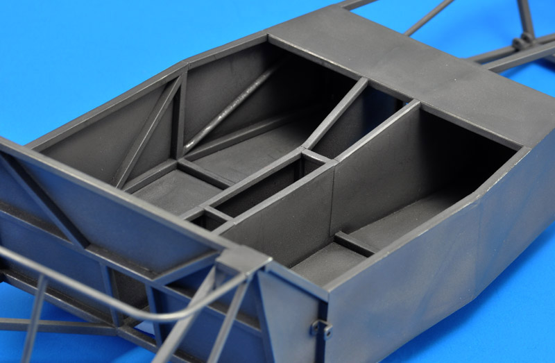
Close-up of the cabin area. The paint on the diagonal roughly left of the center of the photo has worn quite a bit from the puppet getting in and out. I will have to repaint the area.
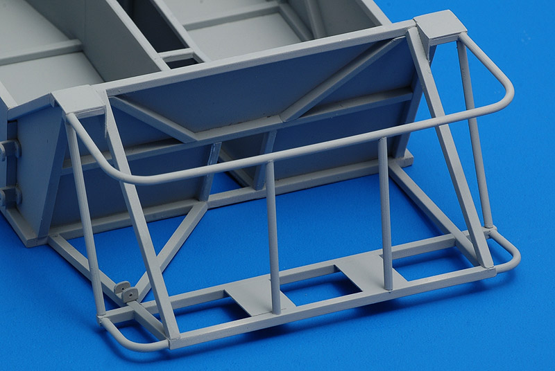
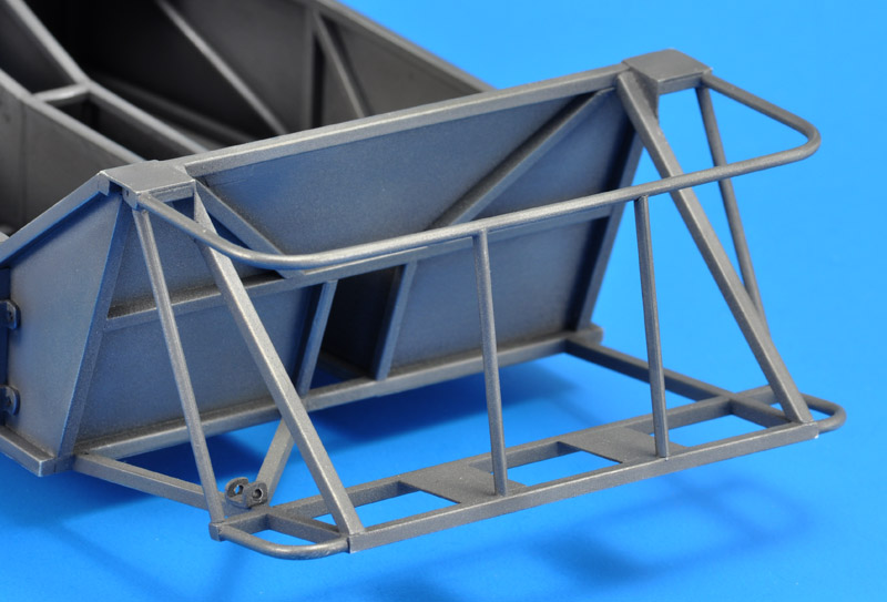
Close-up of the rear side of the chassis. I like the combination of square and round tubing. I am tempted to start building a drive train and suspension to fill this area.  
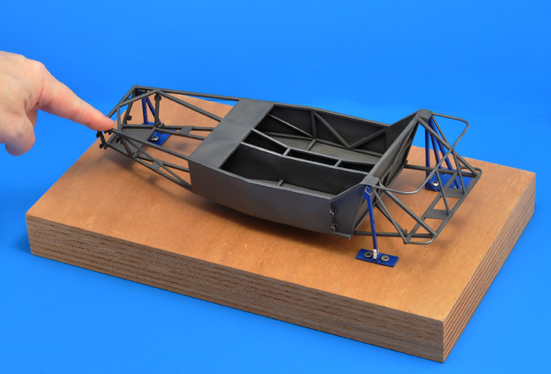
One of my reasons for building this model was my interest in the torsional stiffness of this type of chassis. I built a scale torsion test rig, using a very thick piece of plywood as a base.

The rear right suspension attachment is restrained in three directions (longitudinal, lateral and vertical), the front right suspension attachment is restrained in two directions (lateral and vertical), and the rear right suspension attachment is restrained in one direction (vertical). This set-up prevents that the test rig adds to the torsional stiffness of the chassis.

By pushing down on the left front suspension attachment point, you can study the deformation of the chassis. It's amazing to see how the rear left suspension attachment moves forward during such a test.
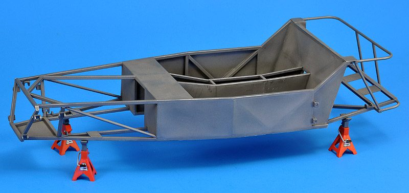
Here's the chassis posed on four axle stands. The master axle stand was 3D printed, but extremely fragile, and it was damaged in multiple places. With considerable effort I repaired it, but I got very frustrated with the parts. I'm also very worried about the long-term material properties of printed parts; I would expect them to get even more brittle. Therefore I made a silicone rubber mould to cast much more durable resin copies. I'm not a fan of aftermarket suppliers that sell parts straight from the printer; I would rather buy traditional cast resin parts.  


Errors

I found out later that I had made a substantial error during the painting phase. The book tells you to build the floor panel and the rearmost side panel from 1.6 mm steel sheet. The remainder is to be built from 1.2 mm aluminium sheet. Therefore I should not have painted the chassis steel colour overall. Considering the daunting masking job inside the cabin to correct this, I will most likely leave the model this way.

Another error involves the floor panel. I cut away the paneling below the prop shaft, whereas the book doesn't.

Not an error but more an improvement: I later enlarged the holes in all brackets, to make them look more realistic.


Links


Return to models page