3D printed Martian Tripod
| Way back in 1991, I started a scratch-build of a Martian Tripod Fighting Machine, but I did not get far, lacking the required skills. In 2025, I started the build of a 3D printed model. |
| Way back in 1991, I started a scratch-build of a Martian Tripod Fighting Machine, but I did not get far, lacking the required skills. In 2025, I started the build of a 3D printed model. |
| I started buying Fine Scale Modeler in 1989, and I also bought the November 1990 issue. I loved the article by Dan Thompson about scratch building a Martian Invader. | 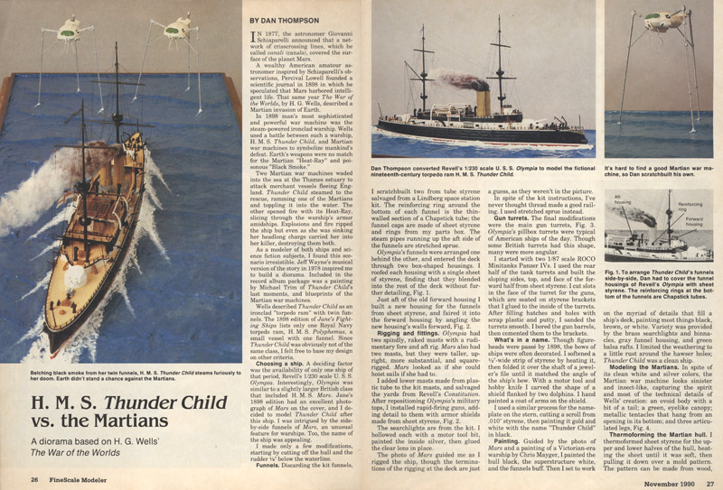
|
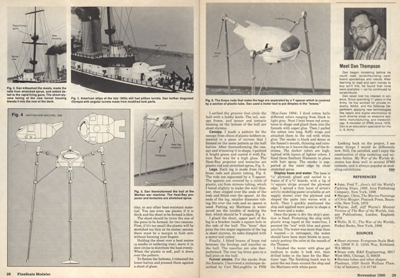
| The article included a drawing, that looked very suitable as a basis for my own model of a Tripod. |
| Following the FSM article, I made masters for the smash-forming process. I used balsa wood and a lot of car body filler, I seem to remember Valma. Lacking a better plan, I used the same scale as the article drawings. On the right is the master of the eyes, that I never finished properly. | 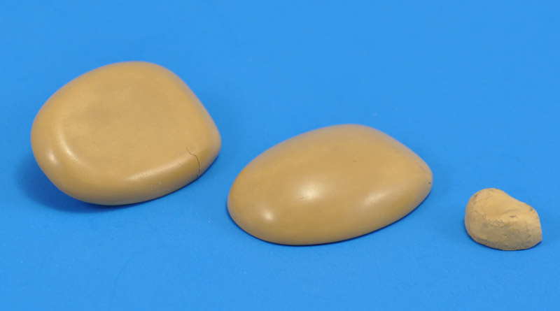
|
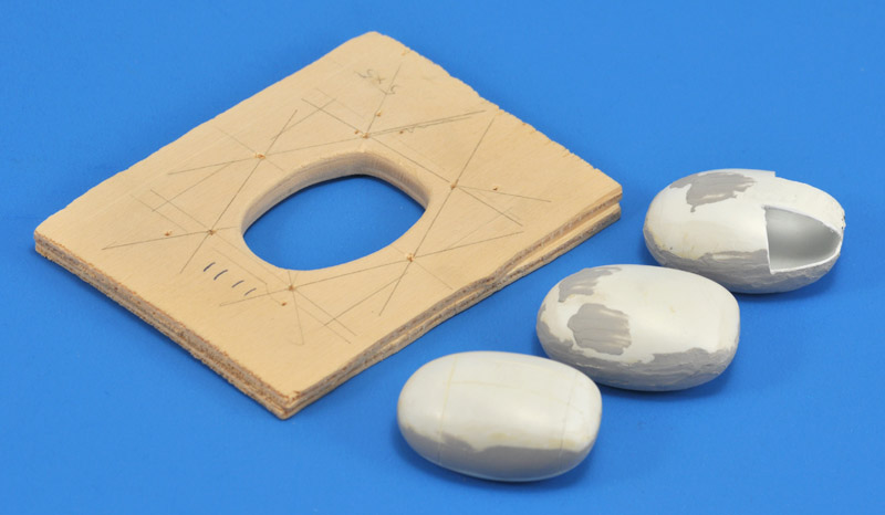
| The blankholder was cut from scrap pieces of plywood. I made several bodies, the two parts are glued together here. They are in different stages of finishing with filler. The one at the rear was partially cut-up, for another model where I needed a double-curved part. |
| I reused the blankholder to make a scribing jig for the assembled body. A few blocks of wood made a scribing guide. | 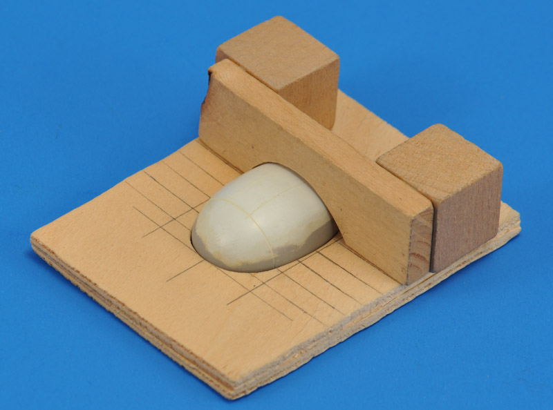
|
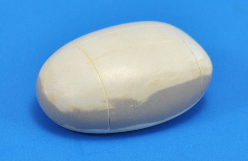
| I started engraving several panel lines, following the FSM drawing. But this is where the project stalled. |
| 3D modeler Christoph Caina shares his STL files for free on at least two 3D file sharing sites: Printables: Jeff Wayne - Musical Version of The War of The Worlds - Martian Tripod / Fighting Machine and Thingiverse: Jeff Wayne Martian Fighting Machine / Tripod (fixed). It looks excellent to my eye, although I later found some shortcomings in the legs. | 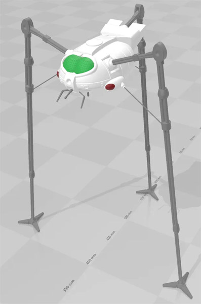
|
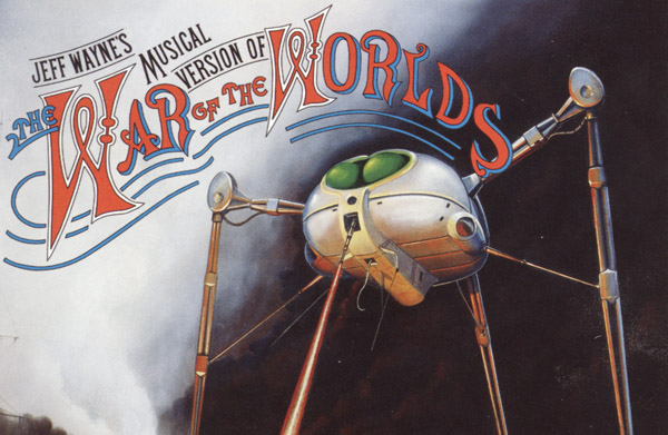
| I decided that the 1978 album cover (see top of page) would be the primary reference. Secondary references were the drawings in the booklet included in the double album, shown here. This still left some details open for interpretation. | 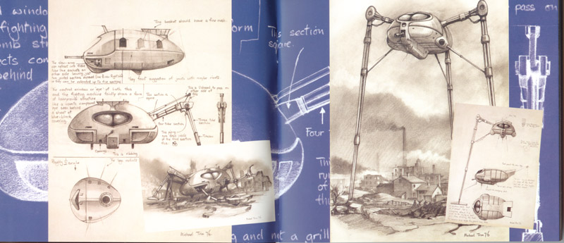
|
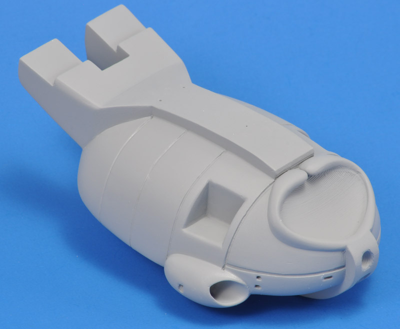
| Club member Wim printed several Tripod bodies on his filament printer. I got two of them: the dark grey one is in two halves and printed in PLA, the light grey is in one piece and printed in PET-G. The latter also has a modified tail, so I could mount the rear leg like the left and right legs. | 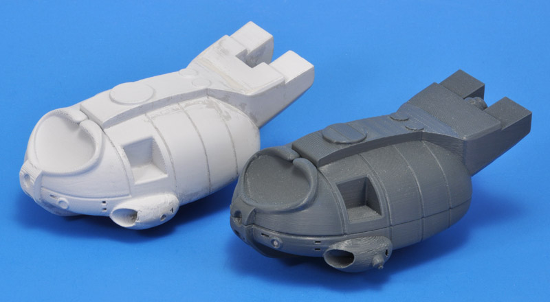
|
| The filament printed parts are rough. I decided to approach it as an experiment, so see whether such a part was usable, albeit with a lot of work. I decided to do the job step by step, with a lot of patience, knowing it would be a silly amount of work. Only the resolution to never ever do this again kept me going. I will never build a filament-printed model again - I will gladly pay for a more expensive resin print. |
| I started with AK spray can primer, but immediately saw that wouldn't work, the dried primer layers are way too thin. I switched to Mr Surfacer 500, applied in two layers, and that really filled the printing steps. A lot of sanding later, the rear half started to look decent. | 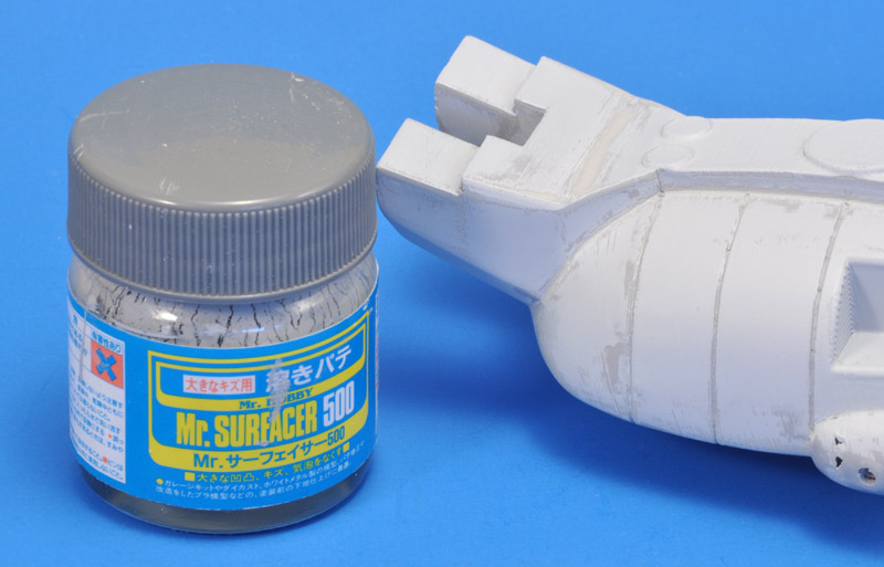
|
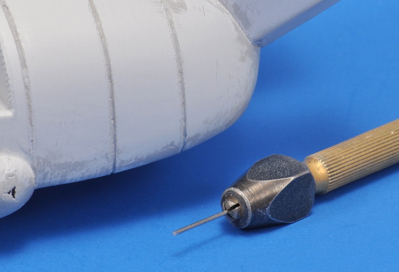
| I made a simple tool from 0.75 mm spring steel wire, sanding the end at a 45 degree angle. It worked really well as a chisel to clean up the panel lines around the body. But you cannot really see the results well, it needs another coat of primer or paint. |
| I switched to good old Humbrol 127 at this point, since spray can primer has so much solvent that a fresh layer made previous layers bubble in places, especially in corners. The first result was promising: the rear of the body was really taking shape. However, a thick coat of enamel paint takes several days, maybe a week, to cure properly. | 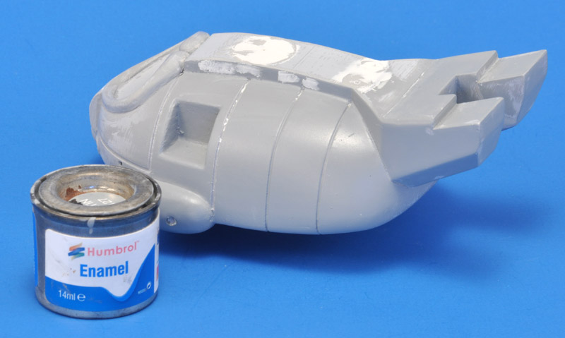
|
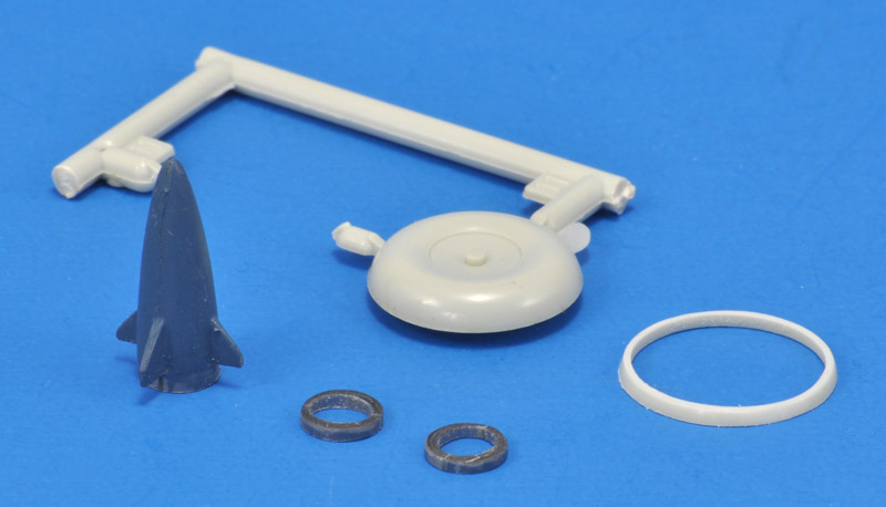
| The three circular hatches would be very difficult to make smooth. I decided to cut them off, as can be seen in the previous photo. My spares box yielded two large wheels and a missile, and I cut 1 mm slices from them. |
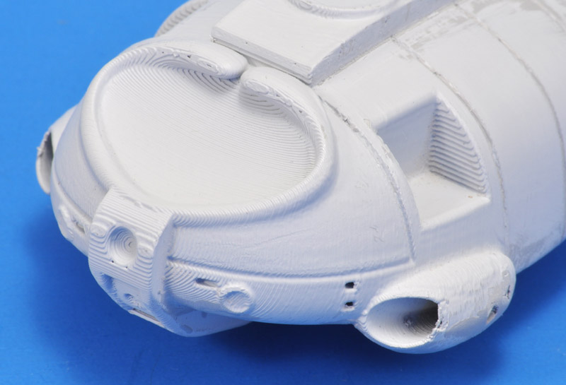
| While smoothening the rough 3D print, I noted several differences between the STL model and the album cover version. The former had 'headlights' on the nose, rounded edges on the ventral 'box' and two 'thingies' halfway the bottom side. I removed or changed all. I also added an extra panel line on the forward end of the bottom side, in line with the panel line on the upper side. | 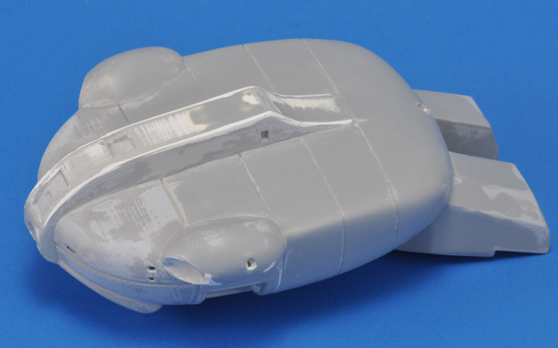
|
| The formerly rough print is slowly becoming nice and smooth. |
| I used Apoxie and my 0.75 mm steel wire to make the panel lines uniform and smooth. Here's the treatment of the lower side, with the excess that was pushed out still present. | 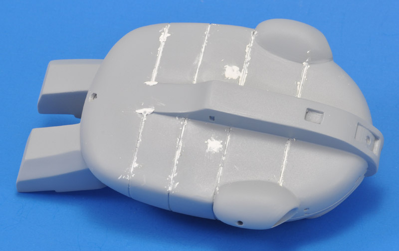
|
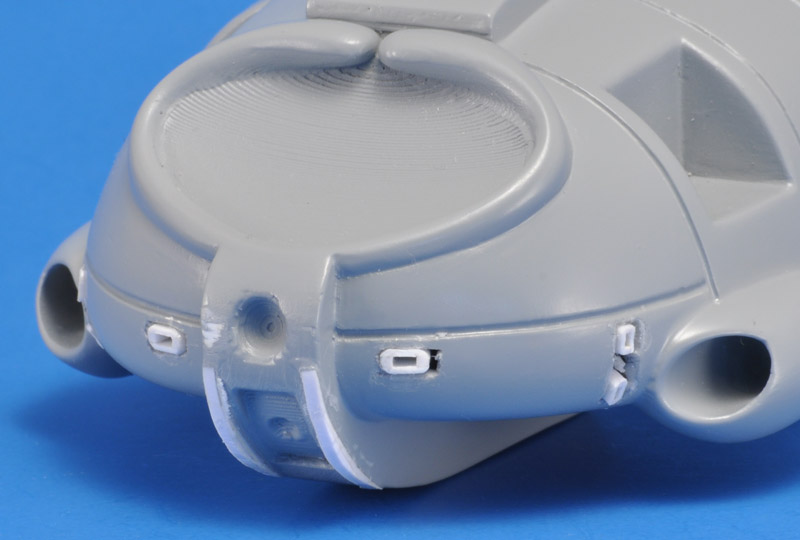
| The small openings on the nose were not well defined, and I did not look forward to doing fine cutting in the difficult PET-G material. I also wanted more agreement with the album cover, so the four smaller openings near the side pods had to be rotated 90 degrees.
I built small 'ducts' from strip and card, 2.0 x 1.0 mm (inside) for the two larger openings, and 1.3 x 0.5 mm (inside) for the four smaller openings. The holes were cut rough (thank you PET-G), but that allowed positioning the ducts in the right spots. Next will be Apoxie Scult filler, then sanding and repainting. I also glued two layers of 2.0 x 1.0 mm strip on the belly fairing, in order to re-shape the contour locally, more rounded in side view. |
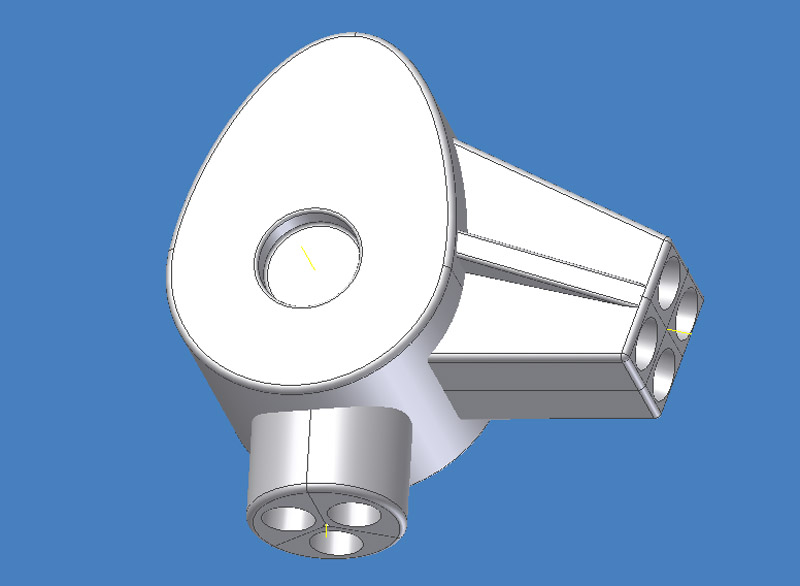
| The legs of Christoph Caina's model do not match the album cover drawing in several ways. They have have parallel tubes between some connectors, and single tubes instead of three tubes between other connectors. I think I understand why, after going through the trouble of redesigning them myself: those connectors were not easy to draw. I also noted the connectors are not faithful to the album cover design, and I decided to 3D CAD design them myself.
The basic shape is very easy to do, but part of the holes for the tubes need to be angled oh-so slightly. Assembly would be near impossible if this wasn't done right - you would get slightly S-shaped bent tubes. I tried three techniques before I found one that worked. On the right you see parallel tubes, on the left the tubes converge. | 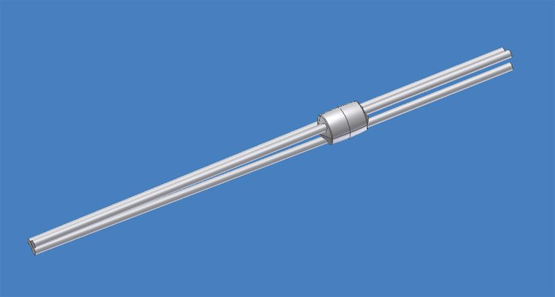
|
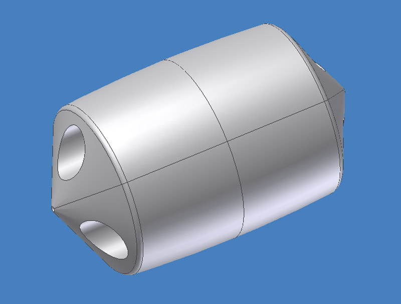
| Here's a close-up of the connector itself. |
| This is the complete set for the vertical part of the leg, of five connectors, bottom to top, shown left to right. With the middle three, we'll have to look carefully at the orientation during assembly with the tubes, since the two ends are different with regards to the tube angles.
For the keen observer: the middle connector still lacks an attachment point for the thin actuator push-pullrod. | 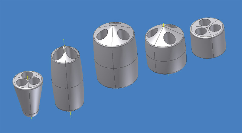
|
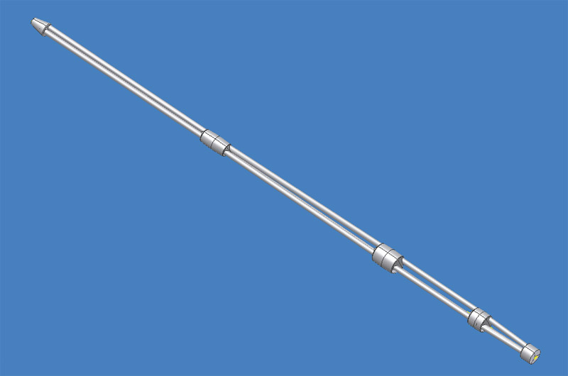
| This is what the leg should look like after assembly. I plan to use bicycle spokes for the tubes / rods. I'll most likely use SWG 13 spokes of ~2,3 mm diameter. |
| Next job was the horizontal part of the leg, with four instead of three tubes between the connectors. It looks massive compared to the vertical part. | 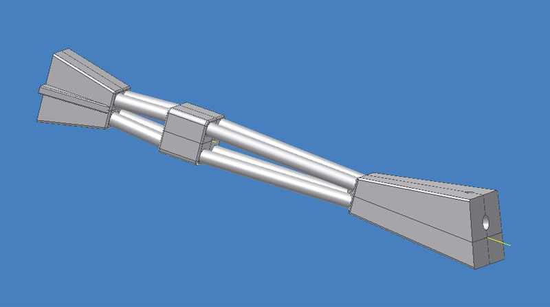
|
| The last part I designed was the 'knee', that combined with the top connector of the vertical part, and the outboard connector of the horizontal part. I couldn't fully match the album cover design of the knee, the album's knee width is too small I believe. |
| Club member Wim printed a few connectors as a test on his resin printer. Several connectors were difficult to print, since in every attitude except perfectly horizontal, they would retain liquid printing resin during the printing process. The connector front right is an example of that.
I had some bad experiences with the low strength and brittleness of printing resin. I plan to make silicone rubber molds of all parts, to cast them in epoxy resin. This will give me connectors that will be many times stronger than the printed parts. I think this will be important to prevent the metal tubing breaking the connectors in case of an accidental bump. | 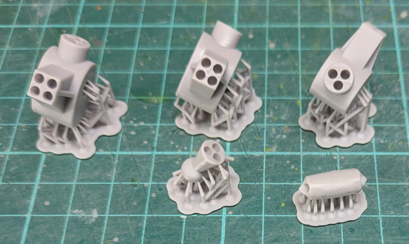
|