Revell 1/48 Me 163B Komet
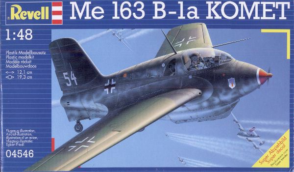
| Although the vast majority of my aircraft models are in 1/72 scale, I couldn't resist the Me 163B in 1/48 scale. I thought it would make a great desk model, flying on a column of rocket smoke. And so another project was started! It would be my first model with displaced control surfaces too.
|
Model quality and accuracy
See the short reports on the Trimaster, Dragon and Revell issues on my Komet website. I planned to correct the nose cone fit problem, the gun bay hatch edges, and the thick trailing edge of the wing roots.
Construction
The wings of model Komets are often difficult to build correctly: the problem is their strong twist, of some seven degrees between root and tip. The twist makes it difficult to judge the dihedral of the wing: when viewed from the front the wing appears to have a little dihedral, but when viewed from the rear it appears to have a strong dihedral. The actual wing has zero degrees dihedral measured at the main spar.
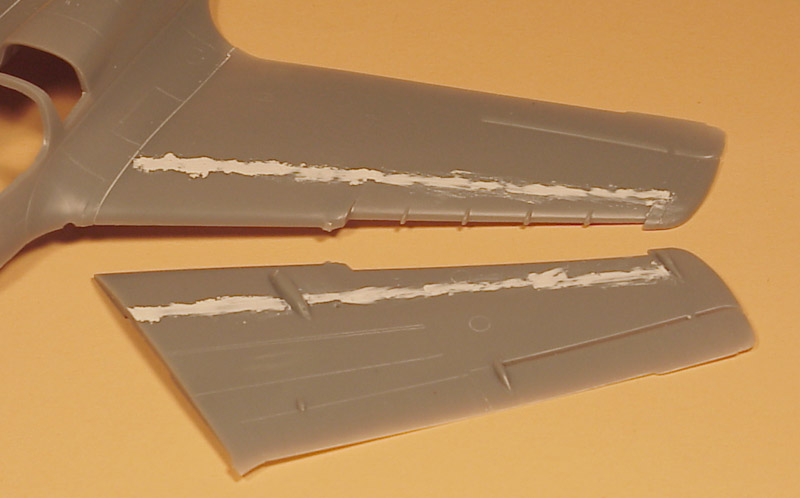
I started by gluing the upper wing halves to the upper fuselage. Next was some Milliput to fill the 'spar' panel line, that does not exist on the real aircraft.
| 
|
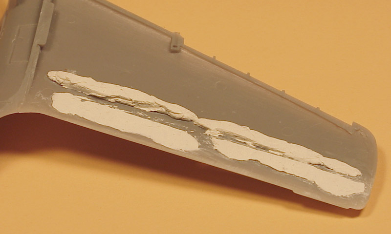
| Because I wanted to maintain a rigid wing after removal of the control surfaces, I created a 'rear spar' before closing the wings. This was done by laying down a 'sausage' of Milliput near the trailing edge and squashing that with the lower wing surfaces, wetted to avoid sticking. It looks pretty ugly, but it worked well. After hardening of the Milliput the the lower wings were attached, with epoxy glue for the Milliput areas.
|
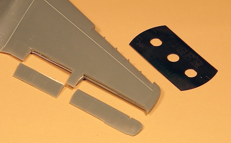
I wanted to try displaced control surfaces on this model. The elevons were easy to removed, since there is a gap between them and the wing. Only the inboard edge required sawing with a JLC razor saw. The trim flaps had to be cut out all the way with the JLC razor saw. Since I wanted to depict an early Komet with short-span trim flaps, I made the inboard cut some 8 mm further outboard. The remaining panel lines and fabric effect were filled.
By the way: what a brilliant invention that razor saw is! I think it's my number one modeling tool.
| 
|

| All gaps in the wing's trailing edge were filled with Milliput and sanded flush. In the photo the left trim flap has been reattached, using a small strip of plastic to create a small leading edge radius. The trim flap is turned down as was common in high-speed flight. The Komet's wing had a small *positive* pitching moment, nose-up, whereas 99.9% of all wings have a negative pitching moment, nose down.
|
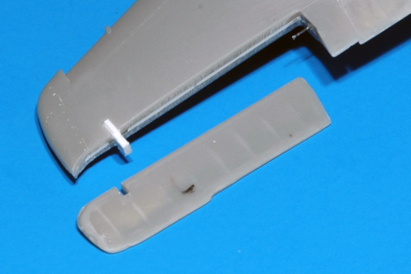
| The elevons were made movable. First I drilled a hole on the inboard attachment point, and a piece of wire was inserted and fixed with superglue. A corresponding hole was drilled in the elevon itself, assuring that an 0.4 mm gap would remain between the wing's trailing edge and the elevons (this measurement was taken from a Messerschmitt drawing). Next I cut out the hinge slot in the elevon, and also cut a corresponding slot in the wing. A laminated piece of plastic card strip was glued in the slot, and cut to size. It was easier than expected.
| 
|
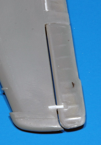
| This photo shows the 0.4 mm slot between the wing's trailing edge and the elevons. During construction I checked it with a suitable piece of plastic card.
|
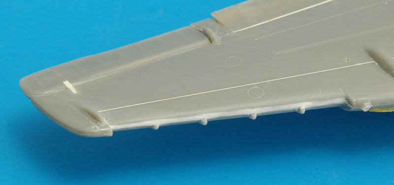
| The leading edge under the leading edge slot required a bit of filler. Maybe my alignment of the wing halves was not perfect.
| 
|
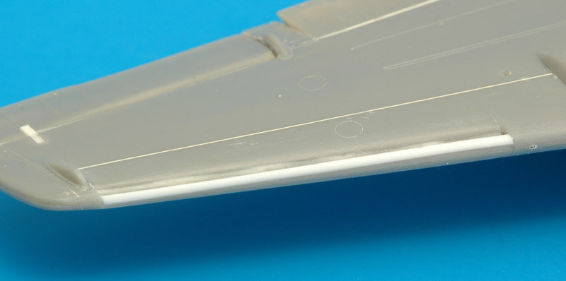
| I found the slats (B5 and B6) very tricky to install, and spent a lot of time aligning them correctly and evenly. After installing the slats, I did not like the appearance of the leading edge: the slat's lower edge sat too high. Therefore I took a piece of 1 mm rod, flattened it on one side, and glued it to the lower side of the slat's leading edge. A lot of sanding later it looked nice.
|
| In front view the modification is clearly visible. I think it matches photos of real Komets a lot better now. Unfortunately I had to sacrifice the pitot tube mounting point, but I prefered having a well-installed slat.
| 
|
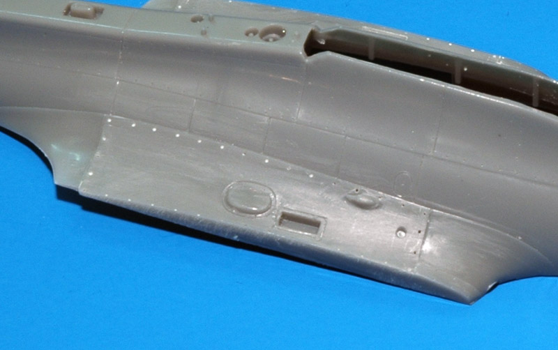
| Trimaster added a strange raised strip around most of the lower gun bay panel. The real thing doesn't have it, so it had to go. To avoid losing the fastener detail, I first drilled out all fasteners with an 0.3 mm drill. The raised strip was then removed by scraping with a small scalpel, followed by a light sanding. The panel is still slightly raised, as museum photos show.
I also removed the wing mounting tabs from the lower fuselage, since they no longer served a purpose, and would make inserting the lower fuselage difficult.
|
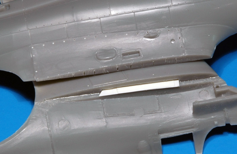
| My odd building sequence had an unexpected advantage when I first tried to fit the lower fuselage. I turned out the fuselage's wing root was thinner than the wing itself. To make the fuselage wing root thicker, I made numerous sawcuts in the edge of the lower fuselage part, so it could be curved a bit more. Next I glued thin plastic card strips on the upper fuselage, until the wing root was thick enough to match the wing. The fuselage now required some force to be closed, but nothing that the glue can't handle.
| 
|
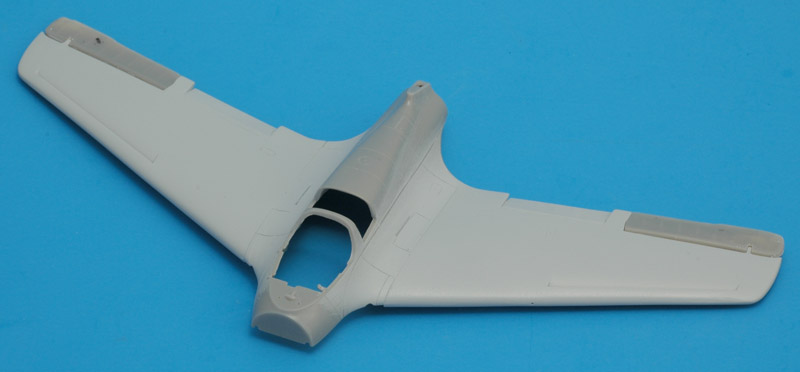
| A round of painting and sanding followed, to eliminate small build defects. The next layer of paint showed a wing that was getting close to being smooth. The modified slots looked good too.
|
A problem that most built Trimaster / Dragon / Revell models show is that there's a shape problem in the nose section. The nosecone does fit properly on the fuselage, as in: they have the same diameter. But when viewed from the top, there's a kink at the joint. There's no kink in the side view. The only solution that I saw was to make the nose slightly unround, by thickening the sides, to remove the kink.
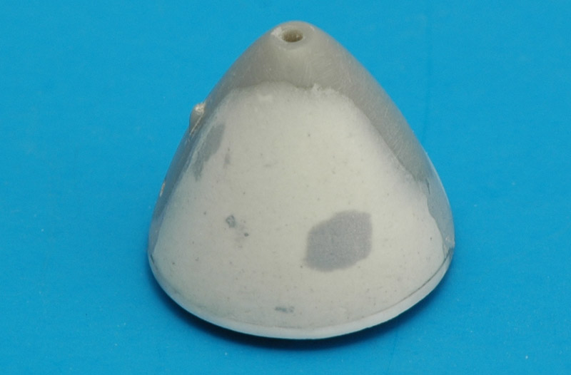
I started by gluing 0.5 mm plastic strip to rear edge of the nose cone. That 0.5 mm thickening was enough to allow a continuous curve of the sides of the nose. Next I sanding the strips to a fine taper near the top and bottom, so the nose would have the original diameter there. I applied Apoxie to build up the nose cone. I then switched to Tamiya putty and then paint to fine-tune the shape modification.
| 
|

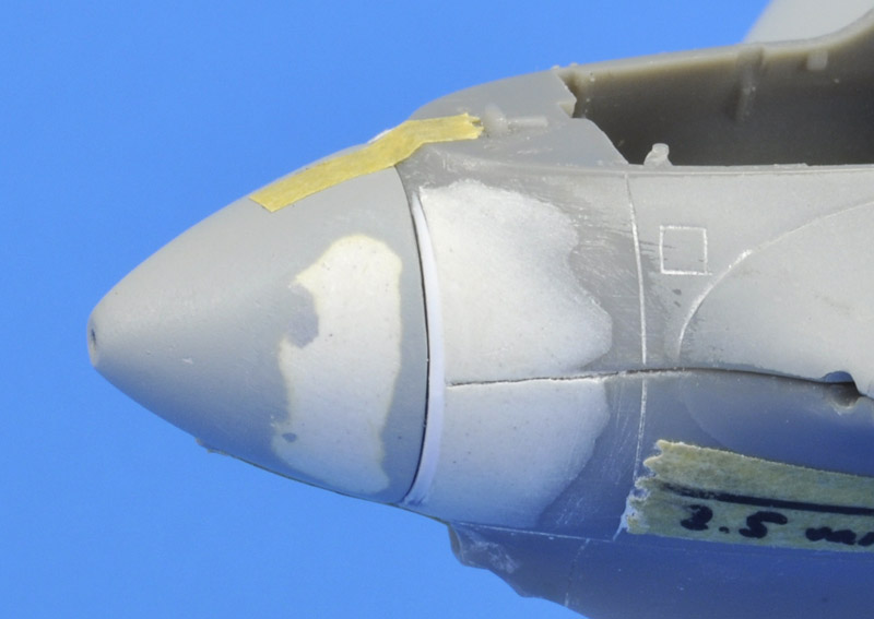
| This view shows the modified nosecone fitted on the unmodified fuselage that is taped together.
|
| The fuselage side of the joint was modified with a similar 0.5 mm plastic strip (tapering to zero top and bottom) and Apoxie, followed by sanding.
| 
|
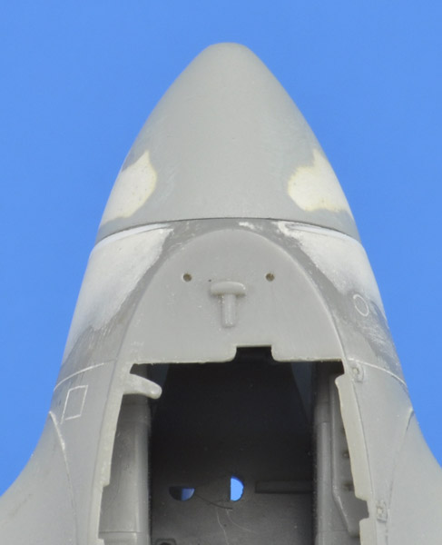
| In this view it can be seen that the rear edge of the nose cone needs a little bit more filler added. But the kink has been eliminated.
|
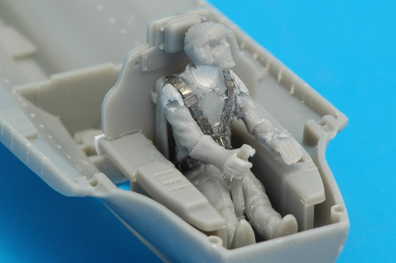
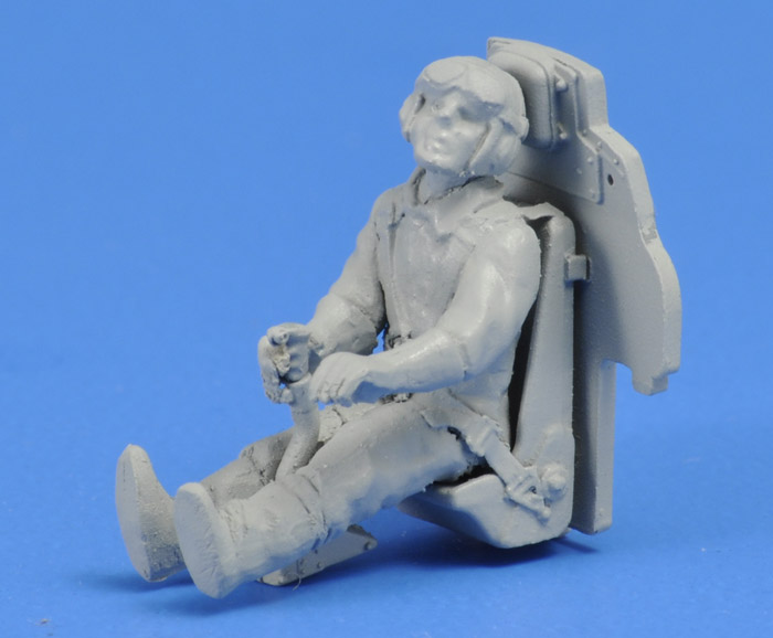
| The model comes with a pilot climbing the boarding ladder, but I want a pilot in the cockpit. I could not find an alternative resin figure that had a leather cap and goggles, so I decided to convert the standing figure to a sitting one. Since I wanted to pose the model in a left turning climb, I had the figure look that direction. Shown here is the first results after one night of work. Still lots to do.
| 
|
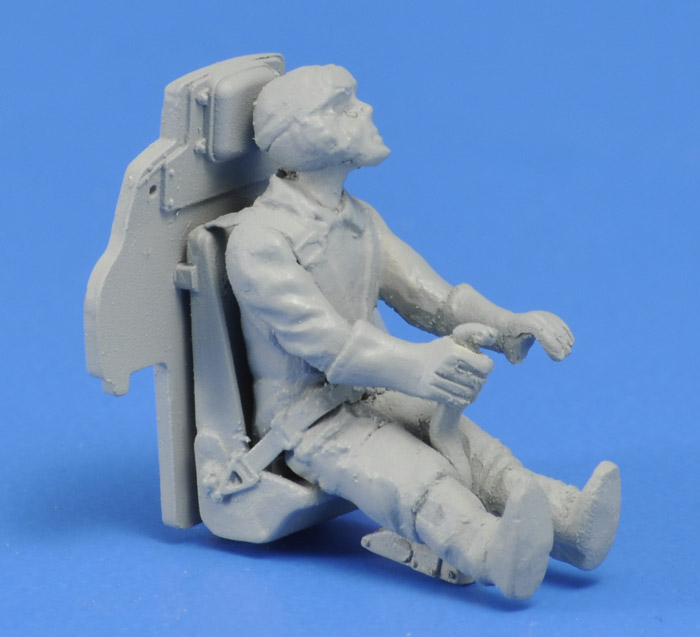
| Humbrol 127 primer paint hides most of the crimes now, but adds a bit of graininess. I see now how oversize the gloves are, maybe I'll work a bit more on them. The pilot's neck is a tad long, but I decided against cutting out a thin slice.
Only at this stage, while watching a Komet video of Rudy Opitz strapping in, I questioned whether the pilot wore a separate parachute harness. He's definitely not wearing one before boarding. I'm not aware that combined harnesses / belts were used in the Komet. According to the Me 163B 'Bedienungsvorschrift', the seat is such that the pilot sits on the parachute, which was probably standard in that era. Considering the unknows, I'll leave my figure as it is.
Later I re-read Mano Ziegler's 'Raketenjäger Me-163', and on page 41 he described that the pilot would adjust the parachute under his bottom after sitting down, to sit comfortably. That would means the parachute harness goes over the protective suit. On page 71 he describes unlocking his parachute harnass and seat belts before exiting the cockpit. And on page 74 he describes that a fellow pilot threw the 'parachute sack' over his shoulder after a flight. On page 117-118 he describes how a fellow pilot grabbed his parachute from the cockpit after a flight.
The photo page next to page 129 shows a pilot dressing in his protective suit and then boarding his aircraft. There is no parachute harnass or parachute to be seen.
|
| Left side view. I still need to put an oxygen mask on, and somehow move those goggles over the pilot's eyes.
| 
|
Colors
Although I love the mottle camouflage of the Komet, I want to paint this one as a 'Versuchs' Komet, as flown early 1944. And of course I picked my favorite Komet, V45, that was first flown as PK+QP and later as 'C1+05'. However, the exact color of these early Komets is not documented. It's a choice between RLM 02, 65 and 76. Or maybe even RLM 63, as proposed by Richard Franks in The Me 163 Komet – A Detailed Guide to the Luftwaffe’s Rocket-Powered Interceptor. I decided to use RLM 76. RLM 02 looks much warmer and darker in black & white photos.
The 'IPMS Color-Cross-Reference Guide' lists FS 36473 as the best match for RLM76. References are #157 (The Official Monogram Painting Guide to German Aircraft 1935-1945 by Kenneth Merrick and Thomas Hitchcock), #110 (FS-595a Equivalent Aircraft Colors of WWII - An Opinion by Michel Franklin) and #212 (Color information on WWII German Luftwaffe usage provided by Guenther Lindow, Andreas Ode and Torsten Ebel, IPMS Germany). In the comments section it is stated 'Add a tiny bit of blue. #3 ('Export Gustavs' no auther listed) call color Weissblau and states it was between 35414 and 35622. Modell-Fan calls is Weissblau'.
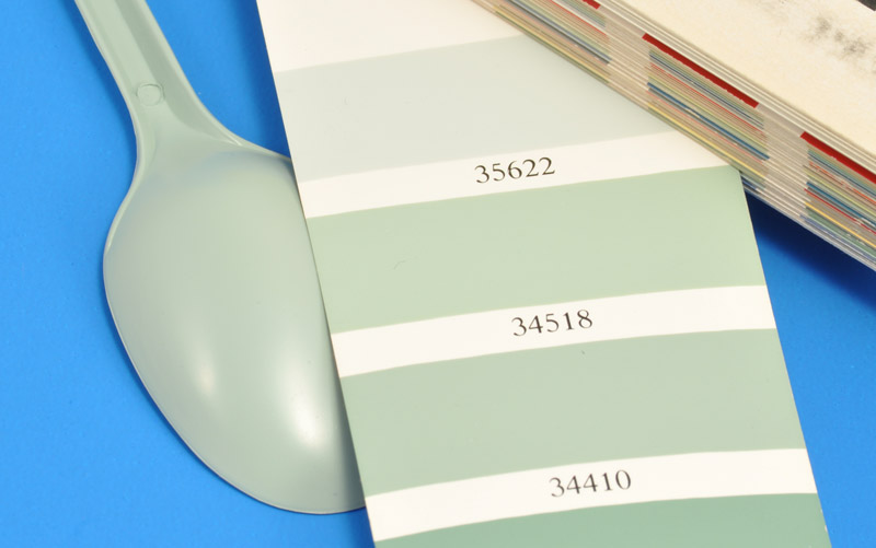
| My favorite paint is MRP (Mr Paint). I shot a 'spoon' sample of MRP-066 RLM76 and was kind of surprised how green it looked. In my FS595B fandeck, halfway between 34518 and 35622 looked like the best match, and they were both on a page with greens.
| 
|
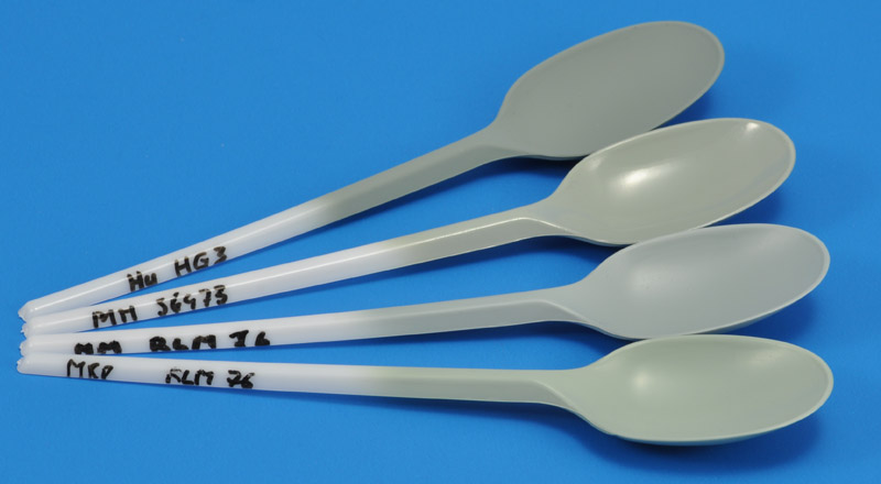
| That in turn made me spray spoon samples of Model Master RLM76, Model Master FS 36473 and Humbrol Authentics HG3 RLM76. That showed that MRP RLM76 is just slightly greener than the Model Master colors, so it's not far off. But I still want to modify it to be a bit more blue, like the Model Master sample.
|
Markings
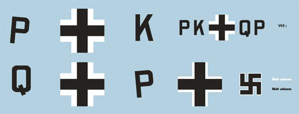
The fuselage markings are clearly visible in the various photos of PK+QP. From photo measurements I concluded that the fuselage crosses are 350 mm. The 'Überführungskennzeichen' or 'Eintragungsbezeichen' PK+QP are 60% of the cross height, as prescribed (see Ullmann 'Oberflächenschutzverfahren' page 127). However the letter style does not agree with the example shown on Ullmann page 128. I drew them by hand following the photos. The swastika is 300 mm, and has a white outline only. Since that type of swastika was not available, I drew it myself. I used the drawing on Ullmann page 130 for that, but it is not correct. I tried again using the text above the drawing, and that worked.
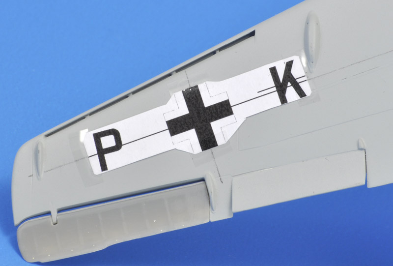
The underwing markings on the right side are visible in an online video. After a long and laborious photo analysis I concluded that the iron cross was 600 mm tall. The position does not agree with the official instruction that says it should be at half span (Ullmann page 130), but it is positioned at 50% chordwise, excluding the control surfaces, as prescribed. The letters are the usual 60% height of the cross, making them 360 mm. They are set a distance from the iron cross, and not as close as on the 'Monotone Me's' decal sheet. Aeromaster, for sister aircraft PK+QL, made the cross 900 mm (black only) and the letters 450 mm, and also had the letters close to the cross - hmmmm... More detail analysis of the underwing markings: I think the 'K' was placed a little more forward to clear the flap. The 'P' appears to be rotated some 5 degrees with respect to the straight line through the letters and the iron cross. This is peculiar, but I decided to copy it in my artwork.
This leaves the upperwing iron crosses, that are very briefly visible in the video. It looks like the lower wing crosses: black with white outline, no black outline. The width can be roughly compared to the trim flap, and I measure 40% of the trim flap length. That would make the cross ~480 mm, but that number does not account for perspective. That makes me guesstimate that they are 600 mm, like the underwing crosses. Ullmann page 132 says that the upper wing crosses have a narrow white stripe (1/20 of the width, instead of 1/8 of the width), so I drew that. The official instruction is that the upper wing cross is positioned 2 meters from the wing tip. That position is quite close to that of the underwing cross, and I decided to copy that position.
| The result was the following simple set of markings. Later I added the armband that the pilots wore over their chemical protection suits, so they could recognised as Germans in case they would have to bail out.
| 
|
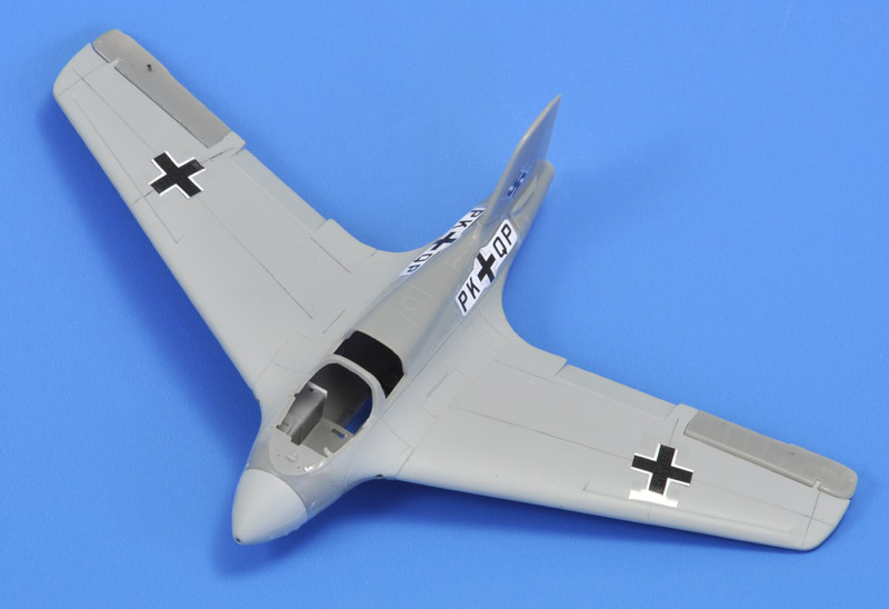
| To test-fit the wing crosses, I drew a 50% chord line (excluding the control surfaces), plus a perpendicular line passing through the filler piece between the trim flap and the elevon. The paper versions of the decals were then positioned accordingly.
|
| I drew a similar 50% chord line on the lower wing sides. The 'K' is positioned 0.9 mm above that line, but I can see now that it's still partially on the flap.
| 
|
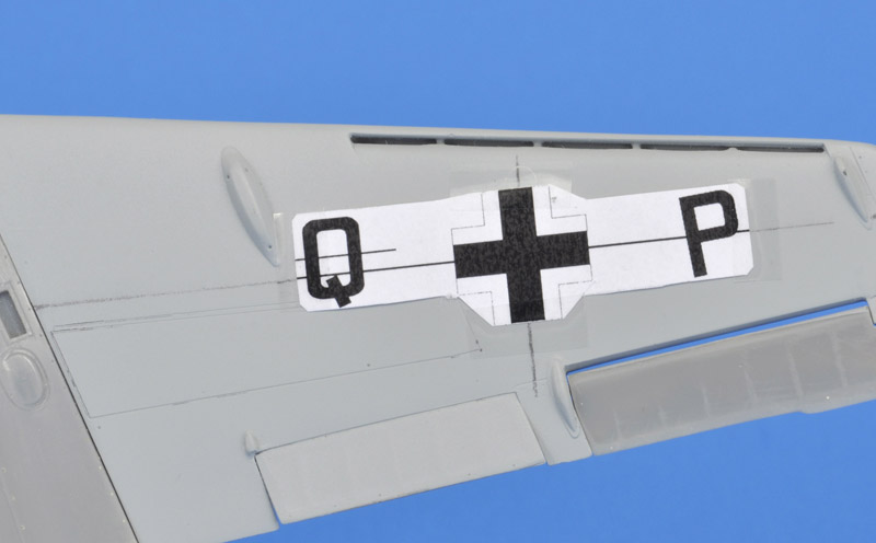
| The 'Q' is positioned 1.7 mm higher, and that makes it clear the flap. I will change the 'K' accodingly. The rotated 'P' is peculiar, but it's what I see in the film footage.
|
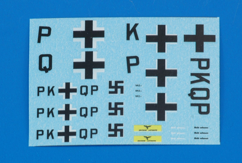
| Here's the print made by SpotModel, with a spare for each marking. The black and white parts have shifted a little, making the swastikas on the edge of unusable.
| 
|
Modeling links
Some related Komet models:
Return to models page


