Photo from 'British piston aero-engines and their aircraft' by Alec Lumsden.
It will be some time before I really have to worry about the engines of my model, but I've tried to find more information on the Bristol Mercury VIII's of the G.I. Hugo Hooftman's book does not have detail pictures of the engine, but fortunately I found a couple of very nice sources:
First was a very complex cutaway drawing of the Bristol Pegasus engine and some photos of both Mercury and Pegasus engines in an old Jane's All The World's Aircraft. The Pegasus is very similar to the Mercury, basically being a Mercury with increased stroke (the longer cylinders show this). Many details are similar, so it's a very useful source for details.
Second was a copy of 'British piston aero-engines and their aircraft' by Alec Lumsden. Although it incorrectly reports that the G.I had the Mercury VIIA fitted, it does have two close-up photographs of the Mercury VIII fitted in the Blenheim bomber. Engine details and fittings are very similar to the G.I installation. And once you know the details, they are visible in G.I pictures too. An example are the white/light grey baffles (airflow director shields) between the cylinders. Once seen in the Blenheim, they can be distinguished in many frontal G.I photographs, and also in the picture of a burnt-out G.I. One major difference between the Blenheim and G.I engines are the vertical pipes alongside the reduction gear; the G.I does not have them.
I received some 1940's/1950's Dutch engine books from Professor Beukers, and to my surprise they contained many drawings and pictures of Mercury and Pegasus. Their titles are 'Motoren voor de voortstuwing van vliegtuigen' by H.A. Jansen and C.W. Schönfeld and 'Vliegtuigmotoren - leerboek voor vliegtuigwerktuigkundigen' by B. Kampschuur.
The TU Delft's library yielded more books with pictures and information, such as 'Aircraft engines Part 2' by A.W. Judge. This book mentioned that all Mercury and Pegasus engines were fitted with Claudel Hobson carburetors. The baffles are also mentioned, being of aluminium construction, with leather seals against the engine cowl.
I divided the photos in three groups: photos of Mercury engines, photos of Pegasus engines, and photos where I cannot see whether it is a Mercury or a Pegasus.
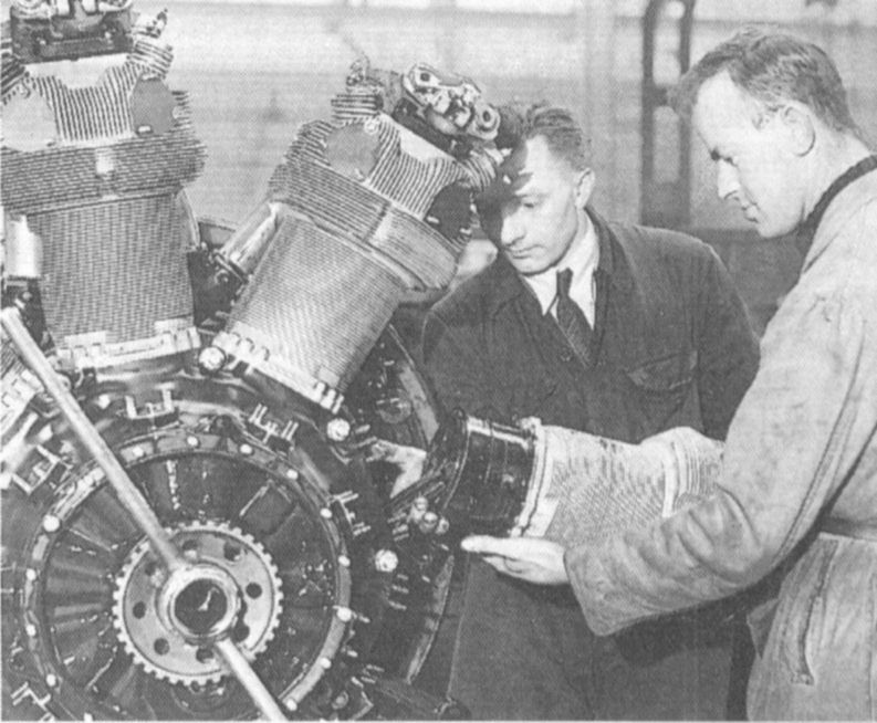
| A Mercury being assembled at the Bristol factory. It shows the very fine cooling fins of Bristol engines.
Photo from 'British piston aero-engines and their aircraft' by Alec Lumsden. | 
|
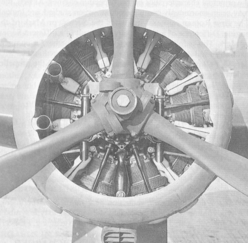
| A Mercury VIII engine installed in a Bristol Blenheim I; this is the same engine as installed in the G.I. Note the white or light grey baffles between the cilinders. The inlet tubes for the oil cooler can be seen on the left; they are in the 11 and 1 o'clock positions on the G.I. Both inlet and exhaust pushrods run together in one oval-section tube, slightly thicker at the root. The vertical tubes alongside the reduction gear are absent on the G.I. The exhaust tubes run forward into a circular collecter pipe that forms the front of the cowling; the installation on the G.I is very similar. A difference is the way the heavy circular exhaust collecter pipe is supported; on the Blenheim short light grey tubes can be seen besides the top propeller blade and below the other two blades. On the G.I. this struts are longer and thinner, and generally more prominent. The propeller and hub look very similar to that of the Fokker G.I.
Photo from 'British piston aero-engines and their aircraft' by Alec Lumsden. |
| The same Mercury VIII engine in a Blenheim I as shown in the previous picture, again showing great detail. The baffles can be clearly seen; they also completely hide the ignition wires in a front view. The neatly engineered cover over the valve gear is also visible. The exhaust tubes can be seen to run forward into a circular collector pipe.
Photo from 'British piston aero-engines and their aircraft' by Alec Lumsden. | 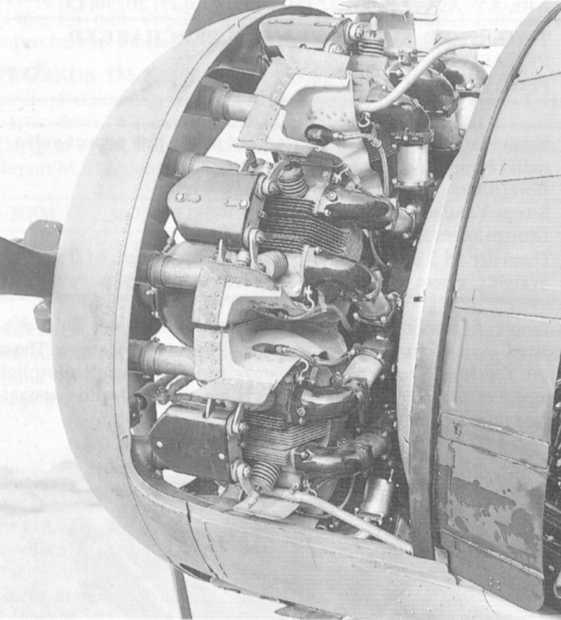
|
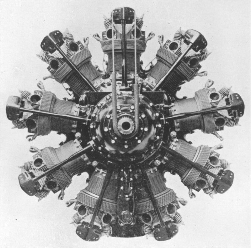
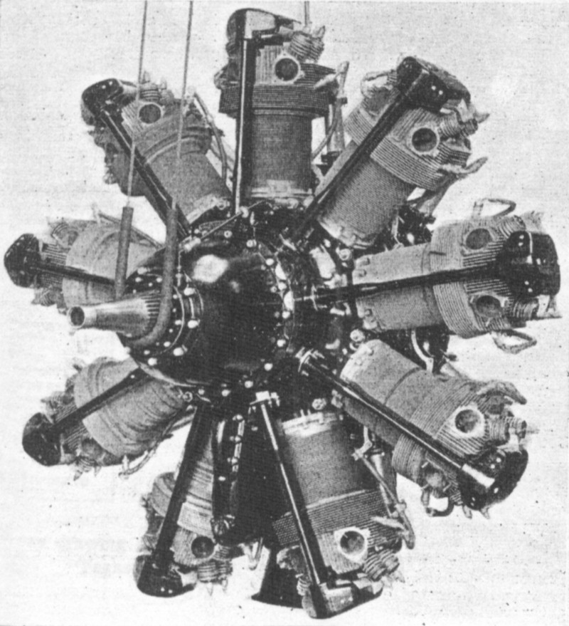
| Front view of the same unspecified model Mercury engine. It nicely shows cilinder, pushrod, crankcase and reduction gear case detail.
Photograph from 'Aircraft engines Part 2' by A.W. Judge |
| Side view of an unspecified model Mercury engine. The caption says it's a 890 hp Mercury, and a table shows Mercury XI and XII achieving this power rating for 'all-out level flight for 5 minutes'. Thus probably being a XII, its detail could be slightly different than tat of a VIII. The reduction gear casing looks a lot like that of the Fokker G.I, and very different from the Blenheim's as seen in the other pictures. The accessories on the back of the engine looks pretty complex to me. Compare it with the cutaway drawing of the Pegasus.
Scan from a copy of 'Jane's All The World's Aircraft', 1939 issue (if I'm correct) | 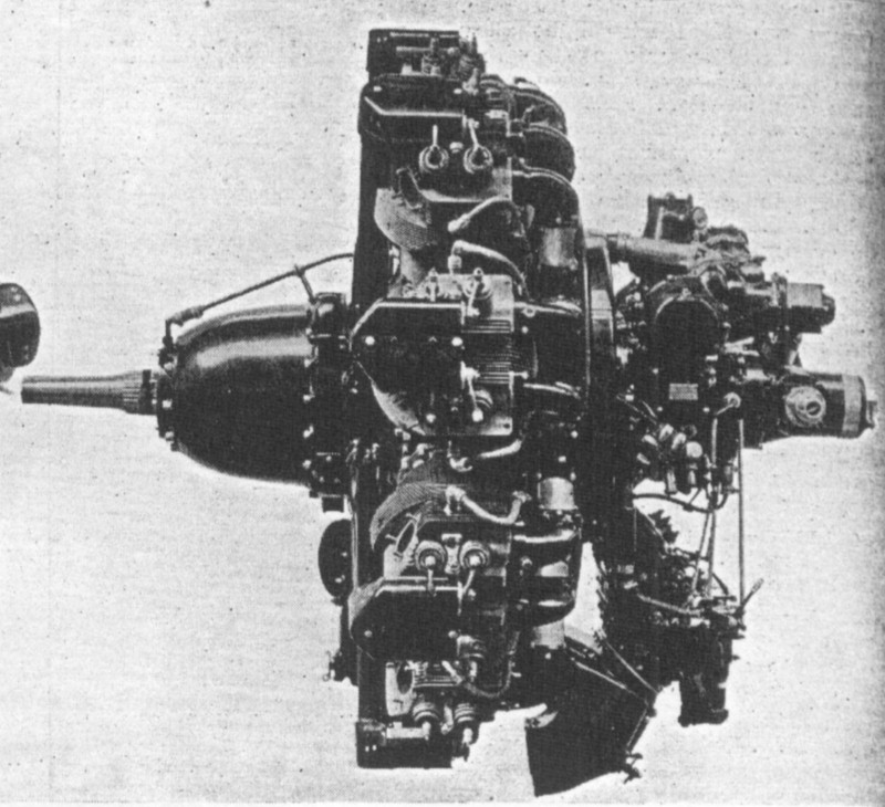
|
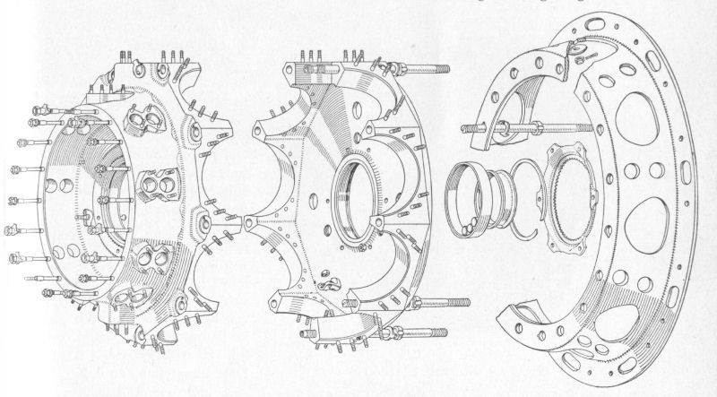
| Mercury crankcase assembly. Note the openings for the pushrods in the front half. The large mounting ring at the rear has openings for the inlet ducts.
Drawing from 'Motoren voor de voortstuwing van vliegtuigen' by H.A. Jansen and C.W. Schönfeld |
| Baffle plate and its means of connection to the cilinder. Note the large opening for the ignition wiring. The short cilinder makes this very likely a Mercury.
Drawing from 'Motoren voor de voortstuwing van vliegtuigen' by H.A. Jansen and C.W. Schönfeld | 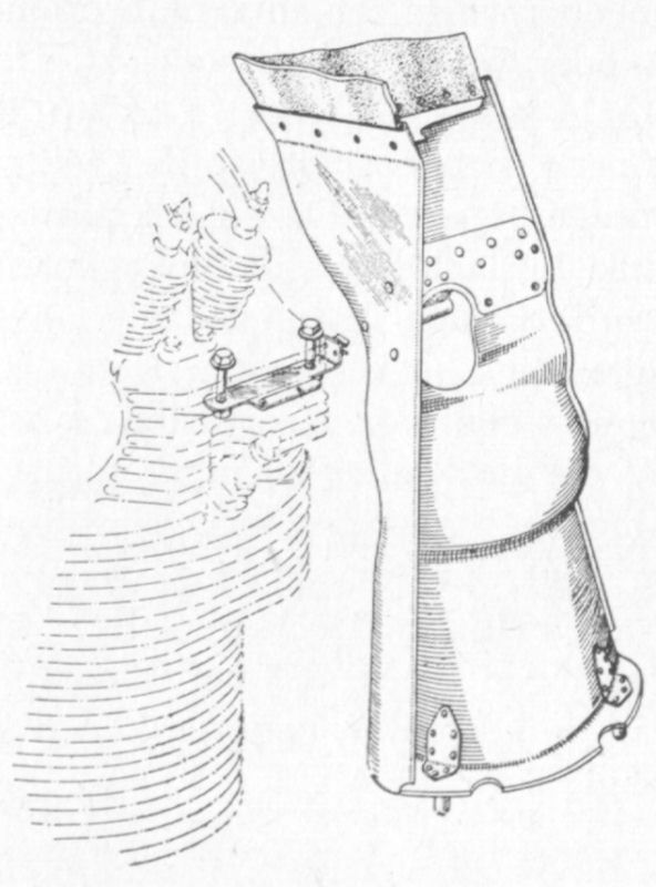
|
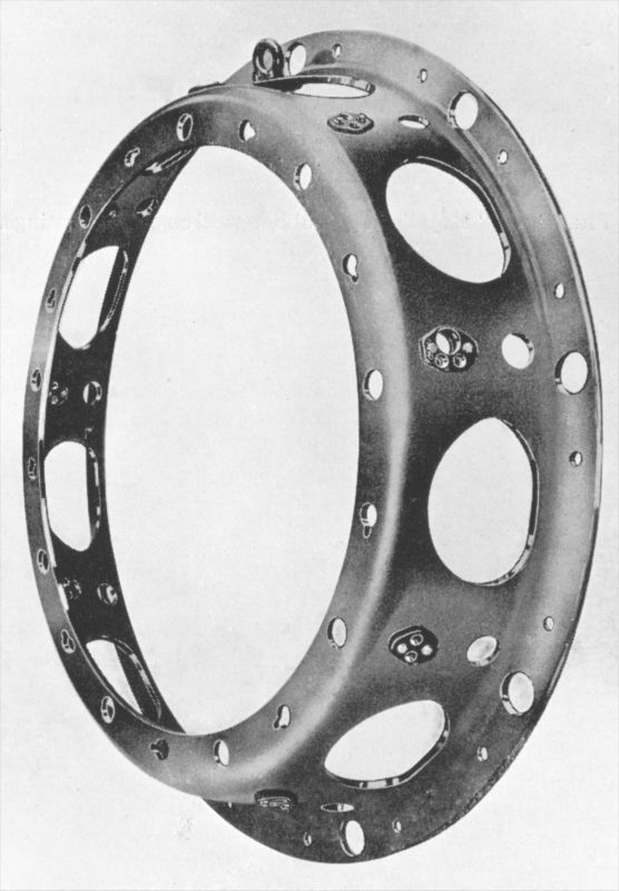
| Seperate view of the mounting ring as seen in the previous illustration.
Photograph from 'Aircraft engines Part 2' by A.W. Judge |
| Overview of the components that make up a single cilinder of a Mercury.
Photograph from 'Aircraft engines Part 2' by A.W. Judge | 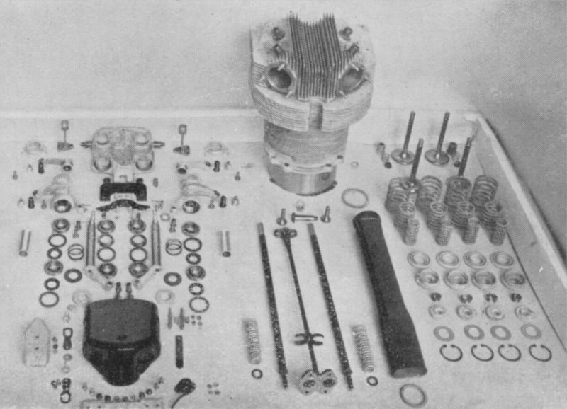
|
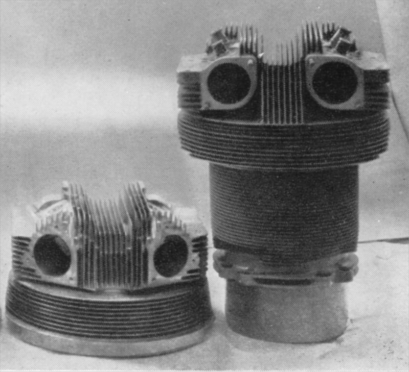
| Mercury cilinder head on the right (front side showing) and Mercury cilinder on the left (rear side showing)
Photograph from 'Aircraft engines Part 2' by A.W. Judge |
| A sectioned Pegasus engine showing interesting details such as the twin pushrods running in an oval-section tube, the valve operating mechanism, the reduction gears, and the exhaust pipes at the front side. The function of the small-diameter pipes running from the base of each cilinder to the cilinder head is unknown to me.
Photo from 'British piston aero-engines and their aircraft' by Alec Lumsden. | 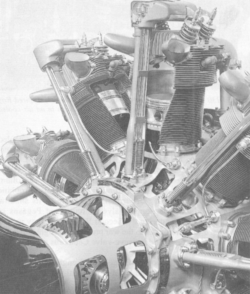
|
| Front/left view of a Pegasus engine (model not specified; only designated as '1000 hp Pegasus'). The longer cilinders compared to the Mercury are clearly visible.
Scan from a copy of 'Jane's All The World's Aircraft', 1939 issue (if I'm correct) |
| Nice rear view showing much of the complex systems normally hiding behind the crankcase and cilinders. It is interesting (and confusing) to compare with the Pegasus cutaway drawing. How much of the systems of the Pegasus is identical to those of the Mercury is not known.
Scan from a copy of 'Jane's All The World's Aircraft', 1939 issue (if I'm correct) | 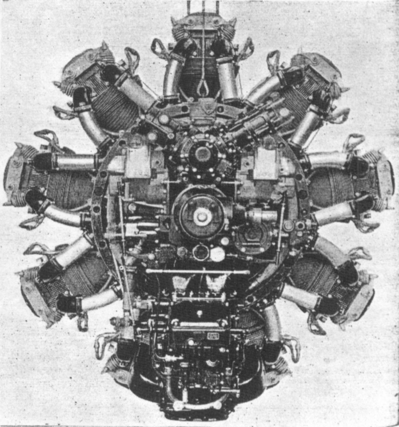
|
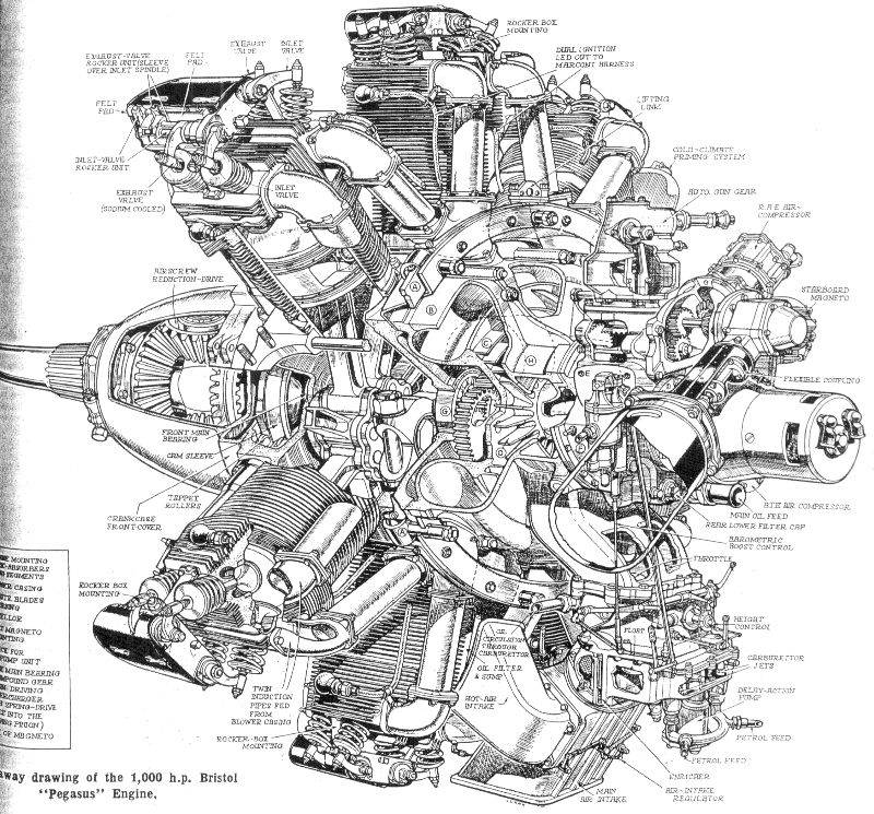
| Very detailed cutaway drawing of a Pegasus engine.
Scan from a copy of 'Jane's All The World's Aircraft', 1939 issue (if I'm correct) |
| Propeller reduction gear assembly of a Pegasus engine.
Drawing from 'Motoren voor de voortstuwing van vliegtuigen' by H.A. Jansen and C.W. Schönfeld | 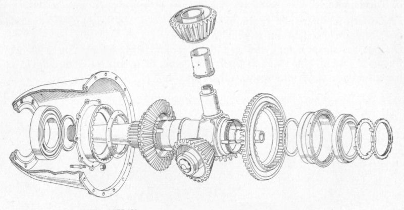
|
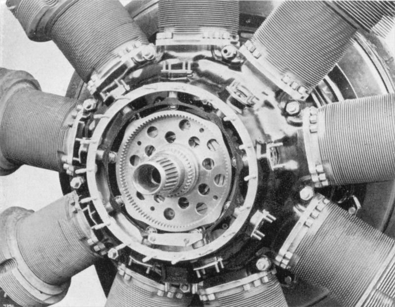
| Pegasus engine showing the camshaft.
Photograph from 'Aircraft engines Part 2' by A.W. Judge |
| Cut-away drawing of the Pegasus engine.
Drawing from 'De vliegtuigmotor en zijn controle-instrumenten' by P.J. Korver | 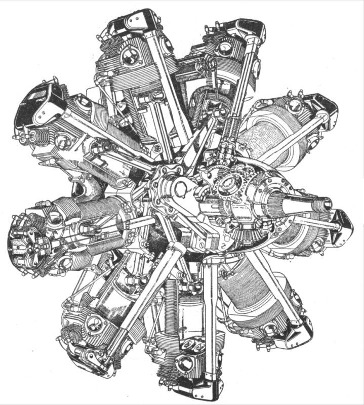
|
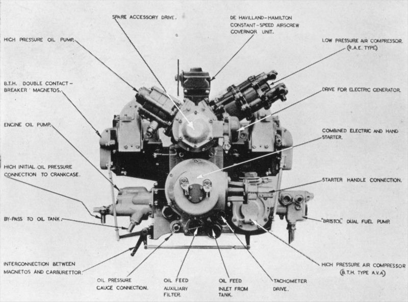
| Photo showing the arrangement of the accessories on the rear side of the engine.
Photograph from 'Aircraft engines Part 2' by A.W. Judge |
| Wiring harness. Although not explicitely attributed to a Bristol Mercury or Pegasus, it looks an awful lot like one of these two. There is a small chance the drawing is shown inverted.
Drawing from 'Motoren voor de voortstuwing van vliegtuigen' by H.A. Jansen and C.W. Schönfeld | 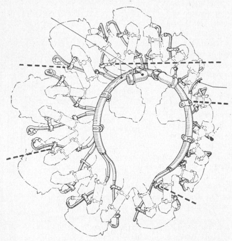
|
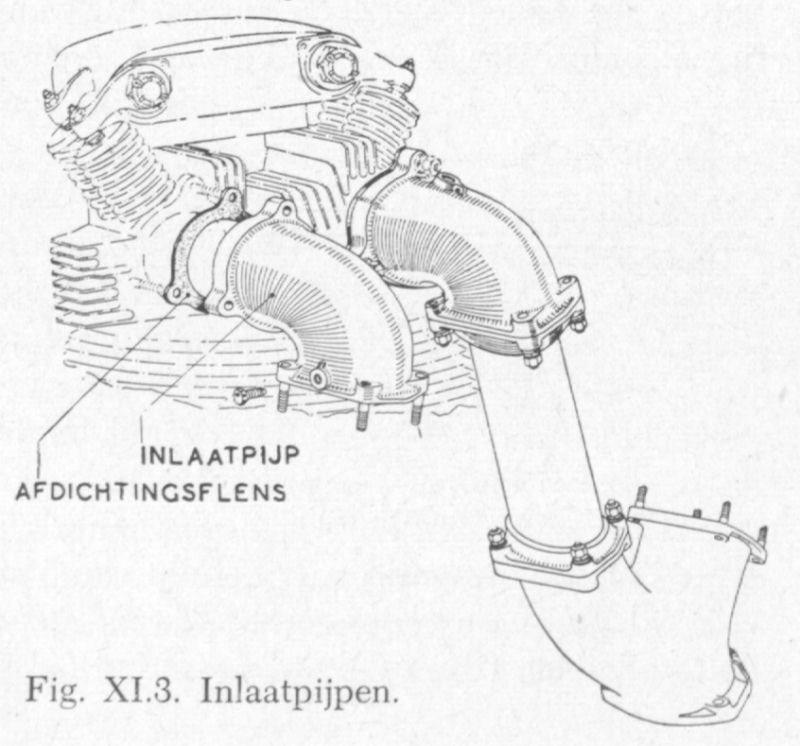
| Inlet duct and cilinder head. Again this drawing is not explicitely identified as a Bristol Mercury or Pegasus, but it looks an awful lot like one of these two.
Drawing from 'Motoren voor de voortstuwing van vliegtuigen' by H.A. Jansen and C.W. Schönfeld |
| Cilinder head assembley. Judging by the long cilinder this appears to be a Pegasus.
Drawing from 'Motoren voor de voortstuwing van vliegtuigen' by H.A. Jansen and C.W. Schönfeld | 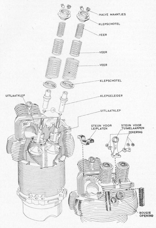
|
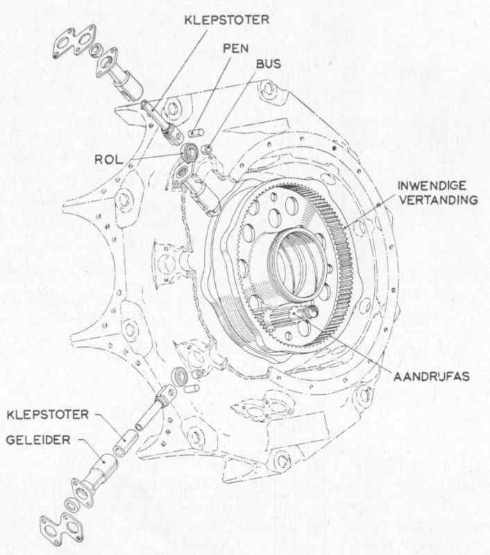
| Camshaft amd pushrod assembly.
Drawing from 'Motoren voor de voortstuwing van vliegtuigen' by H.A. Jansen and C.W. Schönfeld |
| Claudel-Hobson carburetor mounted on a Mercury or Pegasus engine (I think it is a Pegasus).
Photograph from 'Aircraft engines Part 2' by A.W. Judge | 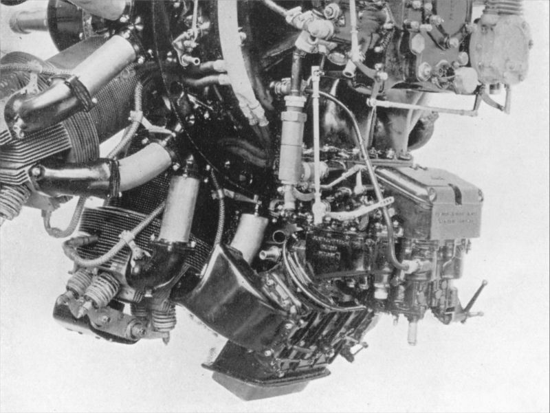
|
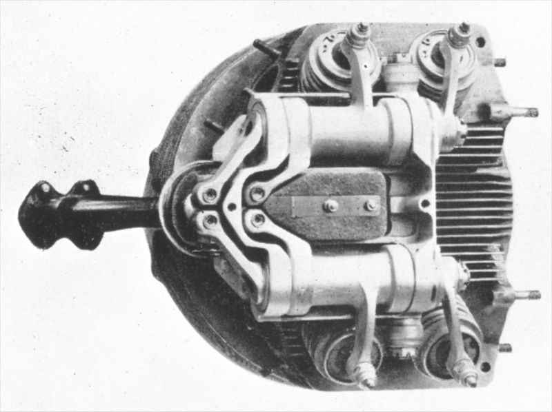
| Valve operating system of a Mercury/Pegasus cilinder
Photograph from 'Aircraft engines Part 2' by A.W. Judge |
| Two views of the exhaust collector ring, including the three three-arm mountings. The mountings are not universal, they differed per aircraft type as far as I can tell.
Photograph from 'Aircraft engines Part 2' by A.W. Judge | 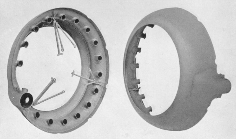
|
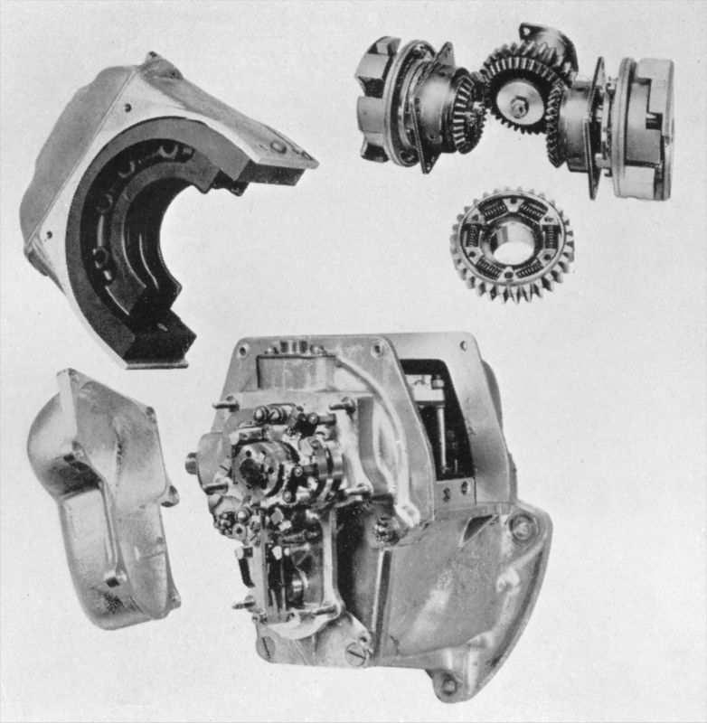
| Various views of the magnetos and their engine drive.
Photograph from 'Aircraft engines Part 2' by A.W. Judge |
| Assembled and disassambled views of the oil pump.
Photograph from 'Aircraft engines Part 2' by A.W. Judge | 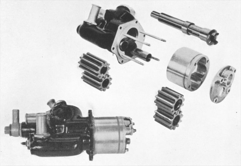
|
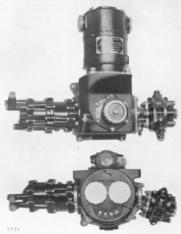
| Assembled and disassambled views of the auxiliary gearbox.
Photograph from 'Aircraft engines Part 2' by A.W. Judge |
Bristol Blenheim Mercury engine cowl bracing close-ups plus baffles discussion, on Britmodeller