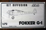
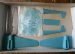
MPM 1/72 Fokker G.I Mercury
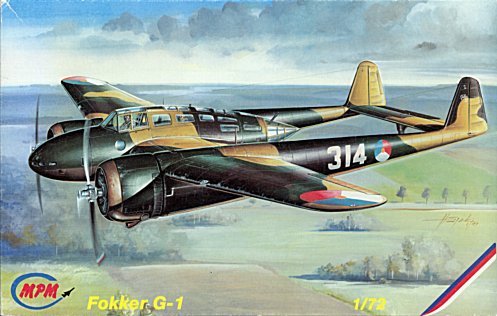
I'm not much into WW II aircraft, except for the Me 163B and two Dutch aircraft: the Fokker G.I and the Curtiss-Wright CW 21B. When MPM released its 1/72 injection moulded kit of the Fokker G.I around 1997 (catalog number 72-034), I bought it. I like the way they executed the kit: the completely clear fuselage halves was an excellent idea. The rest of the kit is typically MPM: a bit rough, no perfect fit, and some photo etch. Around 1999 MPM issued a second version of the kit, packaged in a black and white box, that has additional resin detail parts. This page started out as a build report, but it slowly turned into more of a review when I started finding errors in the model.
Late 2020, Mikro-Mir released a new model of the Fokker G.I Mercury, but I haven't bought it yet.
|
Model description and quality
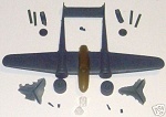
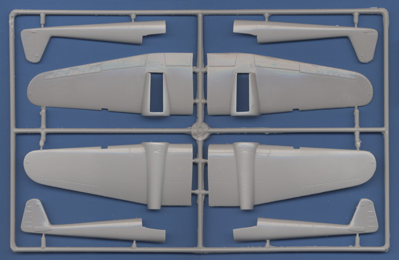
| The MPM G.I is typical for limited-run kits: medium-quality injected parts (some mold damage being visible) with relatively soft detail, no perfect fit, some photo-etch for the cockpit, and nice decals. Here's the sprue with the main airframe parts.
| 
|
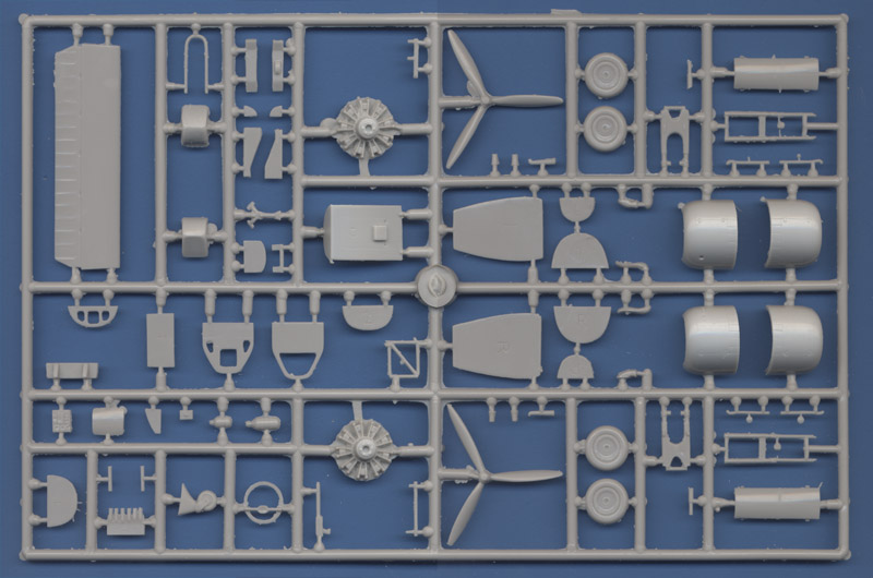
| The other sprue contains the remainder of the parts. The engines are rather bad representations of the Mercury, since they have two pushrods in front of each cylinder, yet the Mercury had them running together through one central tube. The props are rather bad too, firstly because of the crude detailing of the hub and inaccurate blade shape, secondly because they are handed, which the real ones weren't.
|
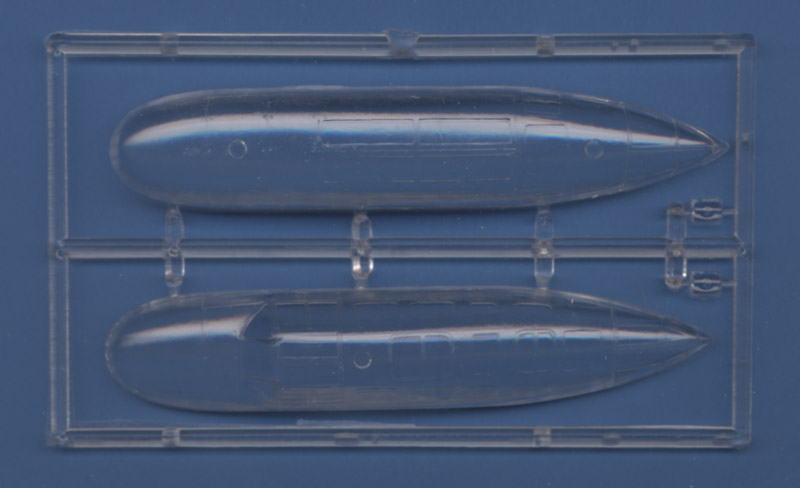
| MPM solved the problem of the multitude of windows in the fuselage pod in a neat way: transparant fuselage halves.
| 
|
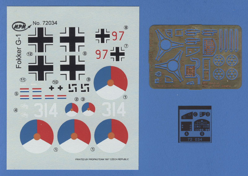
| The decal set is rather small, as usual with MPM, and contains decals for only one Dutch aircraft (314, with pre-war round roundels instead of orange triangles) and peculiarly a German captured G.I (coded '97').
|
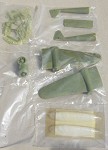
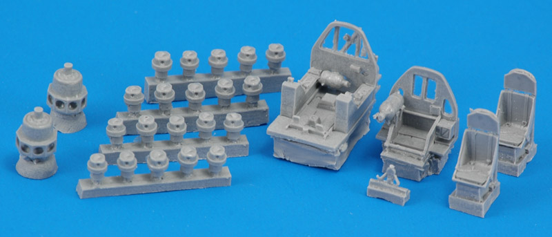
| A later 'Upgraded' issue included a resin set, with both front and rear cockpits, two seats, control column, and two Mercury engines with individual cylinders, and identical decals. Shown here is a copy of the original set. The steering column came out incomplete. The resin engines apparently are exactly to scale, and subsequently do not fit their cowlings, made of non-scale thickness plastic. Very considerable sanding of both the cowling interiors and the cilinder heads is necessary.
| 
|
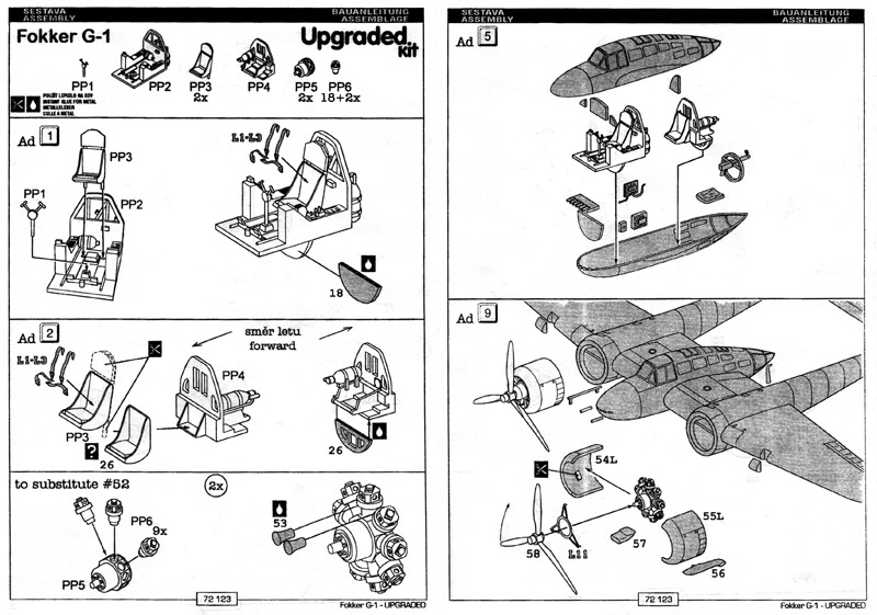
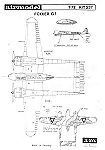
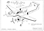
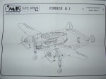
| Here are the instructions for the additional resin parts, courtesy of Eric Verschuur.
|
References
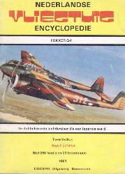
The next step after buying the kit is gathering references. The best G.I source used to Hugo Hooftman's 'Nederlandse vliegtuig encyclopedie: Fokker G.I' that contains some 250 photographs (second and extended issue shown, first issue had a black and white cover photo, and 160 photos). Unfortunately this book is pretty rare these days. I had the luck that a friend had a copy that he donated to me; thanks again, Koen!
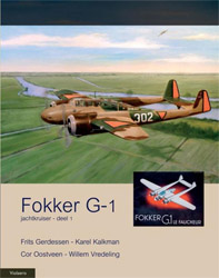
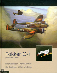
The Stichting Fokker G.I (Fokker G.I Society) has uncovered lots of information on the G.I. Their newsletters often contained very interesting sketches and drawings. Compilations of these newsletters are sold by the Stichting at Dutch airshows, and most likely can be ordered via the website too. They eventually published the ultimate Fokker G.I reference: a set of two books. The planned publication in 2007 was delayed to 2011. The authors are Frits Gerdessen, Karel Kalkman, Cor Oostveen and Willem Vredeling.
Other references worth mentioning are:
the Nederlandse Vereniging van Modelbouwers (NVM)) used to sell a set of nice drawings, but is seems they are no longer available
Profile number 134 by Bart van der Klaauw (1966)
three articles in Air International: October, November and December 1974, Volume 7 numbers 4, 5 and 6. The second issue includes a cutaway drawing. Curiously no writer is mentioned
the MIP magazine of IPMS-NL) had articles on the Fokker G.1 in its 1978-3, 1978-4 and 1979-1 issues. PDFs are available for members
the 5 January 1990 issue of Aviation News. The 'Warpaint' section contains a large number of drawings, detail drawings and paint schemes, all in 1/72 scale, made by Frenchman Hubert Cance (see his website).
'The Last Of The Fightings Fokkers' by Karl Toll, covering both Fokker D-XXI and the G-1 was published in the January 1982 issue of either Wings or Airpower magazine. It contains some detail drawings of the landing gear and bomb bay.
engineer Pim Pouw, member of the Stichting Fokker G.I, makes 3D drawings in Catia of the reverse engineered Fokker G.I. He shows a large number of his drawings of the digital mockup on his site. A fantastic reference!
Model accuracy
Years ago, I wrote about the accuracy that this is a confusing part, since no definitive drawings exist. I was slowly (very slowly) discovering more and more about the model's accuracy. With the two Fokker G1 books from 2011 out, I think nearly all information that could be found is now published. But I haven't updated this accuracy review with all that information though!
I thought the fuselage pod's diameter was too large compared to the engine nacelles. The fuselage pod and the engines almost line up at the lower side, whereas pictures of the real one show that a G.I can make a belly landing without any damage to the fuselage pod. The pod thus became the focus point of my research. Below is a comparison of the fuselage dimensions of the Stichting G.I drawings (scaled back to 1/72 scale), the 2011 G1 books, and the MPM, CMK and Rareplanes models (CMK data courtesy of Sidney de Koning).
Item
| Stichting G.I
drawings 1998
| Fokker G.I
book 2011
| MPM
| CMK
| Rareplanes
|
| Fuselage width @ cockpit rear bulkhead
| ~17.7
|
| 17.1
| 16.3
| ~15.0
|
| Fuselage height @ cockpit rear bulkhead
| 24.4
| 23.1 (p128)
| 24.7
| 24.7
| ~19
|
| Fuselage length
| 90.2
| 92.4 (p121)
| 92.2
| 89.1
| 89
|
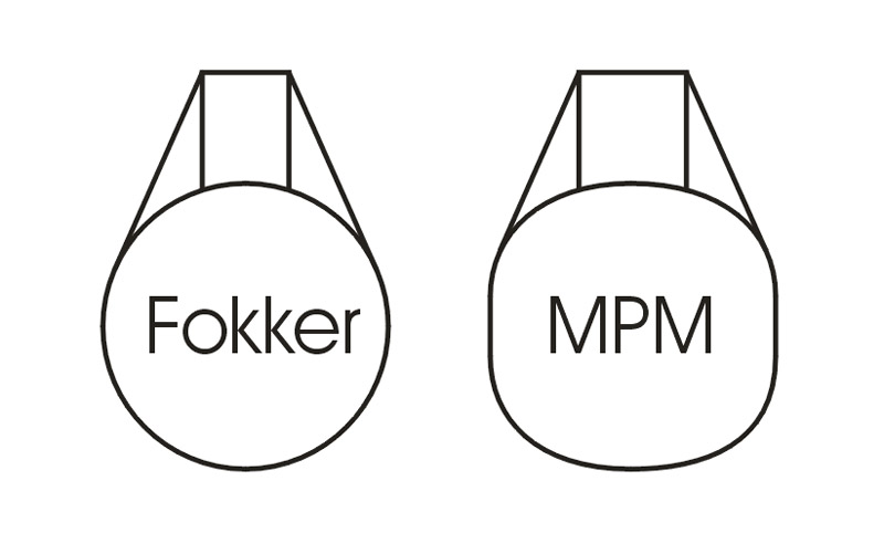
The overall dimensions of the fuselage pod (width, height, length) are within 1 millimeter of the dimensions shown by the 1998 'Stichting Fokker G.I' drawings. Compared the 2011 book data the pod is 1.6 mm too high though. The bad news is that the fuselage should be round, and not squarish like the MPM kit. Fellow G.I builder Sander van Kreijl remarked that the MPM lower fuselage contour in side view is too massive, the fuselage should taper more, giving a more elegant nose. The 'fat' look of the fuselage is probably caused by the fact that the fuselage isn't circular at the sides, but more of a square. Since the cockpit sides are tangential to the fuselage, this causes the whole cockpit area to be too wide. The sketch shows what I mean, but it is not a scale sketch.
The source of this error was also identified: it strongly appears the MPM model is based on a Czech (or Slowak) drawing shown on page 3 of Hooftman's book, drawn by Zdenek Kaláb (Kb signature). The drawing has four fuselage cross sections, and they clearly have flat sides, just like the MPM model. Another clue that this drawing was used for the MPM model is the elevator. The drawing shows 5 cut-outs on the leading edge, just like the model has, but the real aircraft doesn't have them. Other drawings don't have these cut-outs either. It will be interesting to compare this drawing and the 1998 'Stichting Fokker G.I' drawings. It could give us a good analysis of the MPM model.
The table data further suggests that the Rareplanes fuselage is considerably undersize. I have been told that in IPMS-The Netherlands circles of the early eighties it was said that the kit was more suited to be built as a (smaller) G1 Wasp version. The overall dimensions of the MPM and CMK fuselages are close to the best data available. However, the CMK fuselage has a more correct fuselage cross-section it seems (see photos below in the 'Other models' section).
The diameter of the MPM nacelles was found to be correct. They aren't round, but that can be solved easily by shimming the glue joint. But I believe the vertical position of the nacelles is not correct: they are placed too high on the wing. This explains the limited 'ground clearance' of the fuselage pod.
Wing-fuselage assembly
Note: I did the work below before I found the problems with the fuselage.
Due to its configuration and lack of mountings tabs or locating pins, this model isn't easy to assemble accurately. I decided for an approach that deviates from the instructions, and is probably more work, but I think the end result will be better. If you sandwich the finished fuselage pod between the finished wings, there's are considerable risk that the the pod is rotated or at the wrong incidence (pitch angle), or the wings are not mounted at the same level. I wanted to start by gluing together either the upper or lower wing halves and fuselage, and work from there. This allowed good alignment of the wing's dihedral and sweep, the installation of spars (although not really necessary for strength I think) and a good alignment of the fuselage pod with respect to the tail booms. Lastly, the spars would offer me a good starting point for the cockpit interior that I was planning to scratch build. MPM in the mean time has reissued the kit with resin cockpit and engine parts. Possibly I will use some of these parts, but I still intend to largely do the cockpit myself.
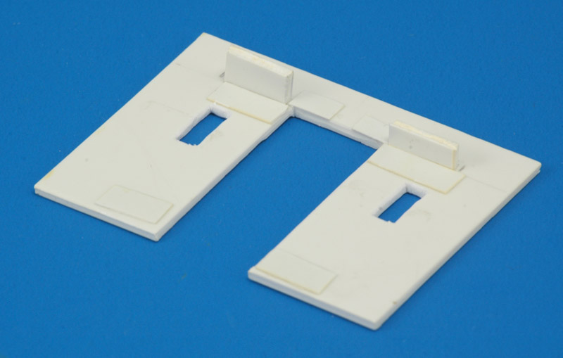
| After some considerations I decided to use the lower half as the starting point. First problem was the alignment of the fuselage and wings. MPM has scribed a wing contour on the transparent fuselage halves, which would align the horizontal break in both the fuselage and the wings. I had my doubts about that: it looked like the gunner's turret would be too low with respect to the tail booms. After a lot of measurements I'm still not 100% sure, but I decided to bring the tail cone up 2.3 millimeters. It looked like the position of the leading edge is OK. Gluing wing halves and fuselage together then became much more difficult. I decided to build a simple jig from plastic card, shown below. I used 2 mm card, built up with 0.3 mm in places that mattered.
| 
|
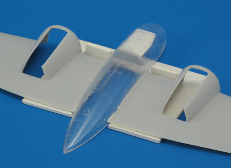
| Before putting the lower wings halves in the jig, I thinned their trailing edges. The jig allowed the lower fuselage to be canted slightly (it rotates around the wing leading edge), while the wing halves were kept horizontally. The 'wing sweep' (none on the center section) was controlled by the stops at the leading edges. It turned out that a small spacer was needed between the rear fuselage and the trailing edge to keep the wing sweep at zero. The Milliput filling around the spacer can be seen in the picture. I hope this will have no consequences for the fit of the horizontal tail between the tail booms!
|
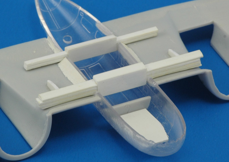
| I used some Milliput to reinforce the joint between the wing halves and the fuselage. Then it was time to put in the spars. Since I was building the kit 'optically', I found the position of the front spar by looking at the rear panel line of the canopy; the panel lines on the wing do not agree with that. The position of the rear spar was determined by looking at the rear windows. I cut out small notches in the clear lower fuselages accordingly. The spars were built up from 1 mm plastic card, made to fit in inside the wing halves. Inside the cockpit they were thickened to the real thickness of the wing. Pieces of 0.25 mm card covered the laminated spars. I also put in a small partial bulkhead just in front of the front spar. It is the forward bulkhead of the bomb bay (yes, it's usually called bomb bay!). To have a starting point for my scratch built interior, I glued a piece of card in the forward fuselage. It sits too deep to serve as the cockpit floor, but it is a start.
| 
|
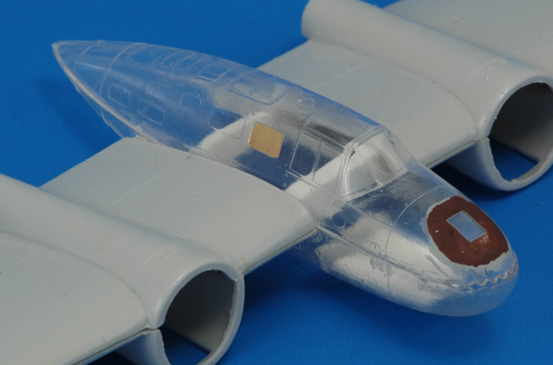
| This is what it looks like with the upper fuselage and wing halves added. The upper fuselage halve also needed small notches to make room for the spars. Don't let the painted window on the nose fool you; it is an experiment to find out the best technique for painting the interior without its light grey color showing on the outside.
Here the assembly stalled, since I thought the fuselage pod was too fat in relation to the engine nacelles.
|
Tail assembly
Now that the situation with the fuselage was clear (but not solved), I continued construction of the model. My biggest worry was the tail assembly. Typical of a limited run kit, the fit of the parts is pretty vague, and a careless modeler can easily end up with a severely mis-aligned model. I decided to take no risks here, and over-engineer things a little.
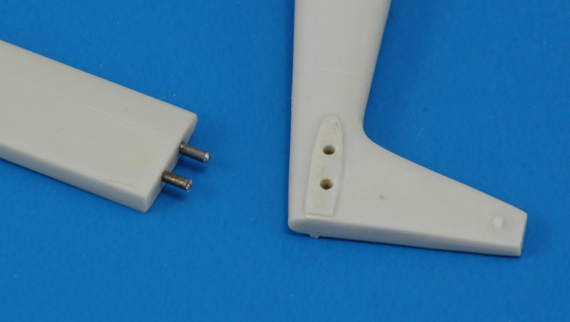
First I wanted to achieve a perfectly square connection between the tail booms and the horizontal tail. I drilled holes through the tail booms and into the horizontal tail, using squares to ensure alignment. I then glued pins in the horizontal tail plane, as shown in the photo. These pins were plastic initially, but due to the tight fit they didn't last long. They were replaced with steel wire later.
Note that the pins' primary function is to ensure proper alignment, allowing assembly and disassembly during construction. I don't think they are necessary from a strength point of view.
| 
|
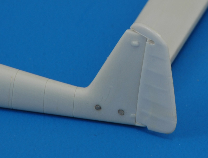
| I removed the rudders. I had never done this before, but it wasn't too complicated. I started with the left rudder, which was easily cut off using a razor blade saw. The hinges were created from pieces of plastic card, and the job was done. I also rescribed the left tail boom. The real tail boom is built up from 7 sections, with a total of 15 frames (visible because of the rivets). MPM correctly engraved 7 panel lines, but the panel lines on the inboard and outboard halves did not line up. Since they were also wrongly positioned, I decided to do them all over.
|
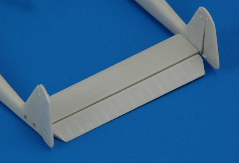
The elevator was a completely different story however. From the five notches moulded in the leading edge of the elevator, I concluded it had five hinges, and that it the leading edge would remain (partly) covered by the trailing edge of the horizontal tail. I cut off the elevator, give the tail plane a 'lip' from my smallest-size plastic strip, and built up a partial leading edge on the elevator.
Only then I started looking for photos of the real thing. Note that this is definitely the wrong order :-) And what did I see: no notches at all, and the leading edge of the elevator projecting above and below the tail plane when it was deflected! This discovery helped to convince me that MPM used the Zdenek Kaláb drawing, as explained above.
After this discovery, I removed the strip from the tail plane and the built-up leading edge on the elevator. Measurements in the Fokker G.I Stichting drawings showed that I should sand the original leading edge round, without any extension. About a year later I found out the truth about the elevator hinges, courtesy of the Stichting Fokker G.I people manning a stand at the Volkel 2004 airshow. The elevator did have five hinges, but due to specially shaped hinge brackets and an unusual elevator structure, they don't show on the top side. Although the drawings did not show it, there must have been slots in the lower side of the elevator, and this is how I will finish my elevator.
| 
|
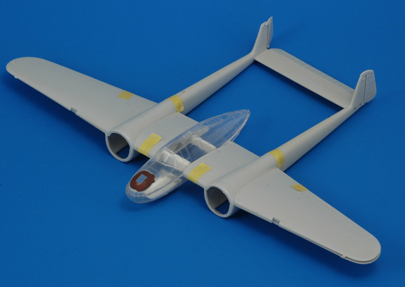
|
With these measures, the whole tail assembly was nicely square, without play between the parts. Time to test-fit them, a moment which I feared because of my slight change of the wing sweep, as explained above. The result was surprisingly good: the tail booms connected nicely with their 'roots' on the wing. And for the first time I saw the complete model, which is always an inspiring moment!
|
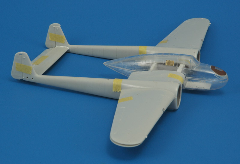
With the model assembled with tape, I could finally study whether my 'titled' fuselage was correct. I selected two almost random real photos, and tried to photograph roughly the same way. In this view the model's tip of the fuselage pod agrees with the photo. But I keep seeing that the model's fuselage pod is slightly too long.
Some more observations. The tailboom ends of the model are too fat compared to the real thing. The vertical tail chord might be too long. The model's horizontal tail's chord looks too large too.
| 
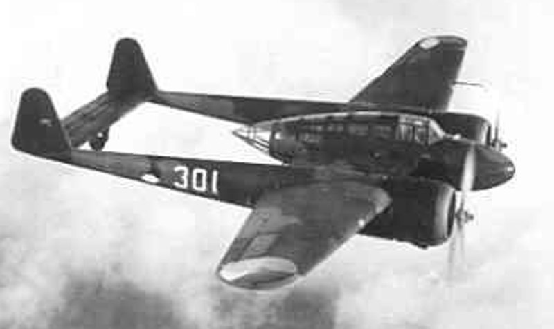
|
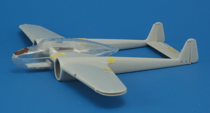
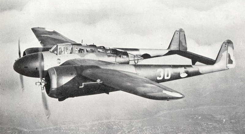
| In this photo set the model's tip of the fuselage pod also agrees with the real photo pretty well.
Other observations are that the incidence angle of the wing against the tailboom appears to be too small - the trailing edge should be lower. The whole tailboom is positioned too high compared to the wing. The dihedral of the model is too small, but that could be the result of the model being just taped together.
|
Fuselage experiments
|
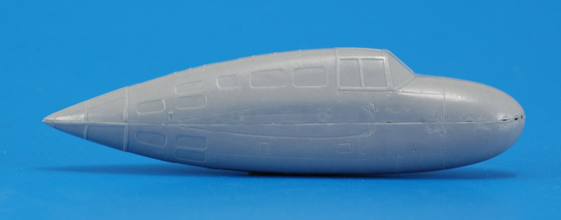
Many, many years later I cast copies in opaque resin to 'see' the shape better. It also meant that I had an 'endless' supply of fuselages to experiment with, before cutting up my one and only MPM fuselage pod.
| 
|
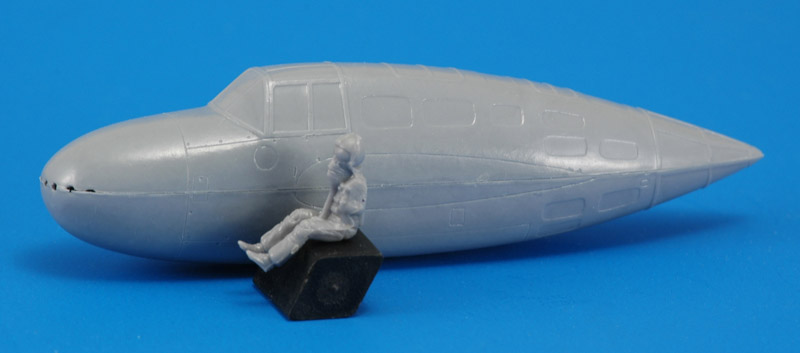
| Here's the fuselage pod with a (modern) pilot posed alongside, for size. It looks quite large to me, not what you would expect from an aircraft design where everything has to be small, light and aerodynamic.
|
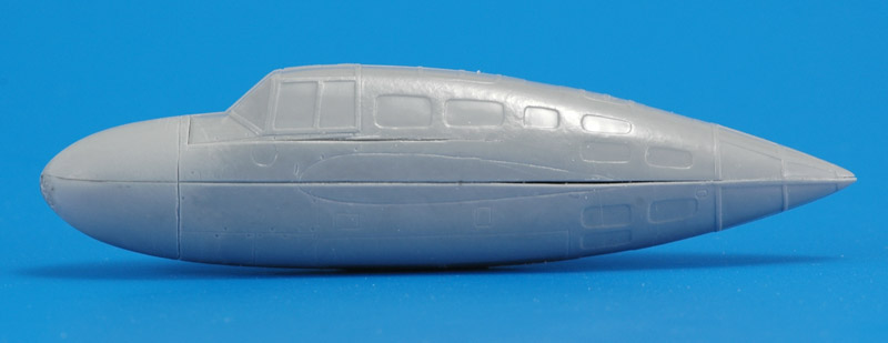
| The first thing I tried to correct the MPM kit is the pod's height, modifying it to the 23.1 mm figure, by taking out 1.6 mm. I tried that on the resin fuselage copy, by removing 0.8 mm from both halves, from the nose down to the end of the wing root. Looking back, I should have removed the full 0.8 mm only to halfway the wing root. The rest needs to be tapered down to the conical rear window section, that cannot be modified without creating new problems. Also, I sanded the lower part of the nose, and added a little material to the nose to make it pointier. I think these modifications look good, but I could not make it as in the photos, because the fuselage at the first panel line is already getting 'square' instead of a pure circle.
| 
|
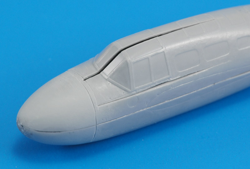
| To solve the problem of the cockpit windows being too wide requires quite an involved operation. First I made a 1 mm wide sawcut at the centerline of the fuselage. It went through the center cabin entry hatch too, where it tapered to nothing. Next I made sawcuts under the side windows, back to roughly the same point. The last sawcut was at the front, just behind the first panel line.
|
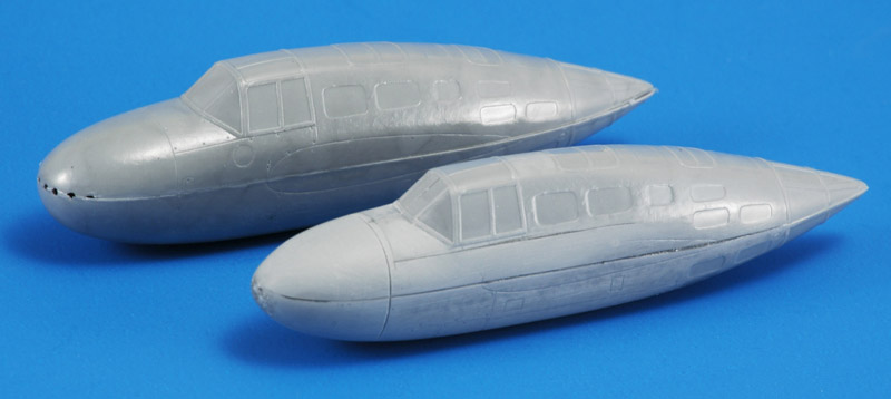
| Next I glued the two parts together on the centerline, and then down on the remainder of the fuselage. This was followed by aggressive scraping of the fuselage sides under the sawcut, to make it circular, and tangential to the windows. I think that the combination of decreased height and narrowed cockpit is very visible in the photo. I believe that the new shape is a lot closer to the original.
| 
|
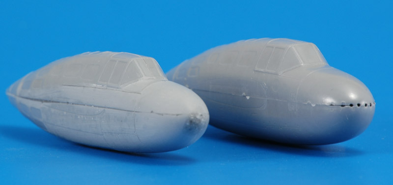
| One more view, showing how much more circular the fuselage has become, plus the narrow windshield. The pod also looks a lot less massive to my eye. The lower side is still a bit squarish, maybe a bit of scraping could be done there.
Now of course one can't do the same modification to the clear fuselage halves of the MPM kit, cutting down the middle of the windshield and other transparancies. That's the next problem to solve!
|
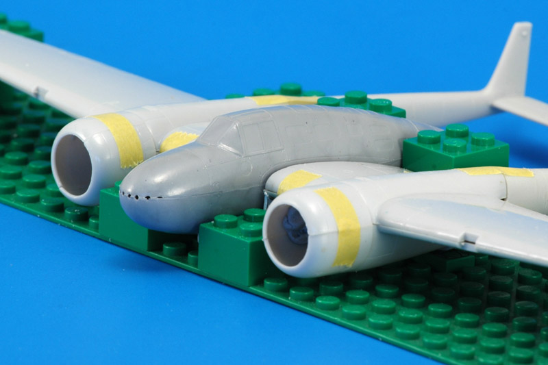
| To judge the effect of the smaller fuselage on my half-built model, I built a Lego jig, and photographed both fuselages set inside the rest of the model. I would say the effect is well visible.
| 
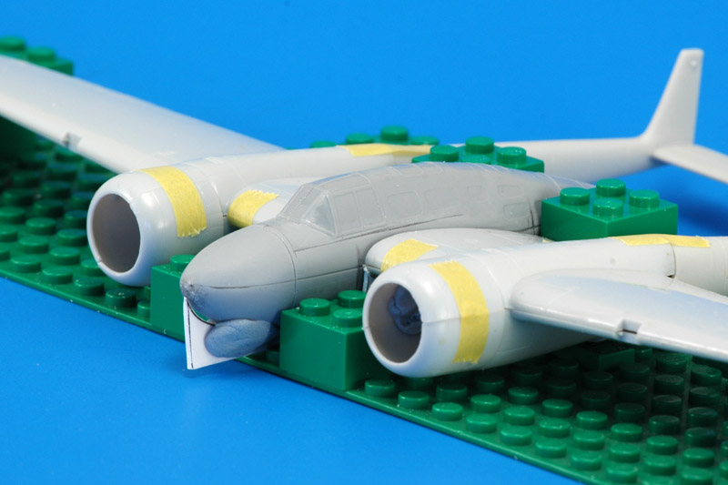
|
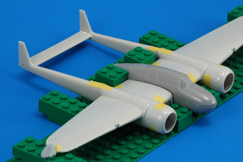
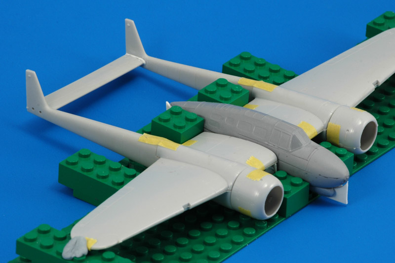
| Here's another view of the model with both fuselage pods in the jig.
|
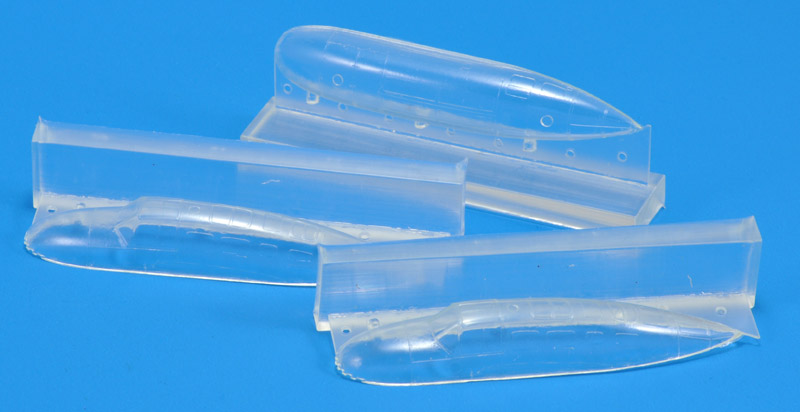
I wanted to experiment a bit with clear resin, and ordered Epoxy Crystal Clear Pro from Silicones And More (a Dutch supplier). The castings were very nice indeed. Maybe I'll cut up a set like I did with the gray polyurethane castings shown above, to correct the fuselage shape.
At room temperature (actually: summer temperatures, 25+ °C), this resin needs around 100 hours to cure to a hard state, judged by pushing a fingernail into the casting block. That's much longer than any epoxy I've worked with before. I did not dare to release it from the mold at that point, fearing that the material still hadn't developed its full material qualities, and would break during the forceful release from the mold (it has severe undercuts). Therefore I did a postcure. The data sheet recommends 40°C for 8 hours. I went a bit further, with approximately 50°C.
| 
|
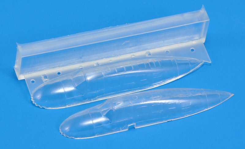
| This is how the kit part compares to the epoxy casting. I would say they are equal in quality.
|
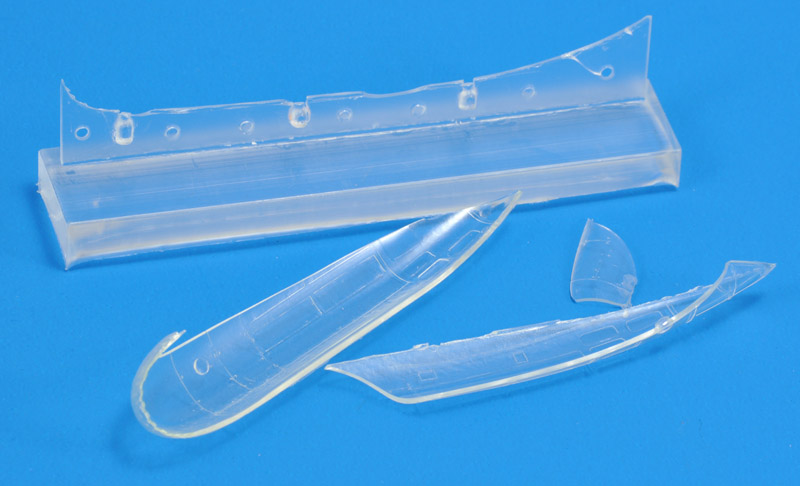
| I'm still learning how this resin works. The 10-hour pot life is extremely long compared to the 7 minutes of my polyurethane resin, and not useful. Probably the resin needs a longer cure to develop its full properties. I probably released this part too early, and it shattered in a brittle fashion, just like clear polystyrene.
| 
|
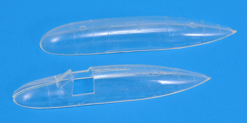
| I had to try the conversion with these parts too. Here's the top fuselage with the canopy side windows removed, a 1 mm section sawed out of the center of the front 60% of the fuselage, and 0.8 mm height removed. The bottom fuselage was only modified with an 0.8 mm height reduction.
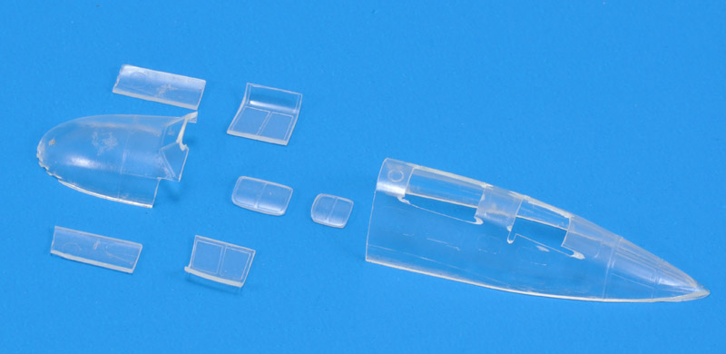
You can't see it in the photo, but the windscreen was cut on its right side, along the frame. Next I removed 1 mm from the center pane, to narrow it the same as the rest of the front fuselage.
|
| The second top half was sacrified to obtain the canopy side windows and the top doors. The material was easy to use, roughly like clear styrene.
| 
|
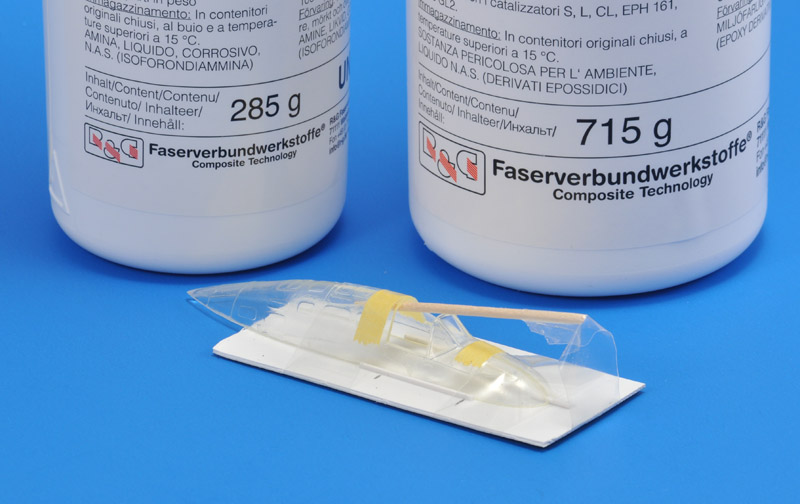
| The first step in gluing back together the top fuselage was the windscreen. I hoped that using a thin epoxy laminating resin would give me a 'seamless' look for the saw cut in the windshield. I used R&G Faserverbundwerkstoffe L-resin with L-hardener. The fuselage was clamped in a makeshift but complex jig, designed to make only the windscreen fit nicely - the rest was for the second step. I used thin paper to apply the resin in the small gap between the frame and the pane.
|
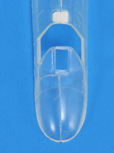
| The second step was gluing the rest with CA glue. I started reinforcing the joint with plastic card behind the cockpit.
| 
|
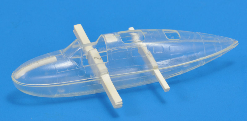
| I made slots for the spars that I had made many years ago, and made a dry assembly. You can see how much narrower the upper fuselage is compared to the lower fuselage. That area would be filled with Apoxie and sanded until the fuselage is circular.
|
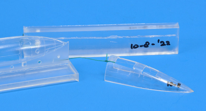
| Generally speaking, epoxy is not UV-resistant. As an extreme test, I put the right-hand pieces outside, facing east, in the sun, for a month. This photo shows the two test pieces, together with a casting stored in a box for the same time (left). I don't see any discoloration, which is excellent news. This photo was made on 7 September 2022, making the exposure 28 days.
| 
|
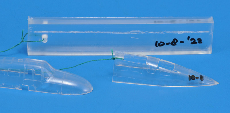
| This photo was made on 24 September 2022, after 45 days of outdoors exposure. The part on the left is the original kit part. I don't see any discoloration.
The exposure was ended on 29 October 2022, since summer had long ended. Total outdoors exposure was 80 days, and I did not see any discoloration in that time. I think the material is safe to use for an indoors display.
|
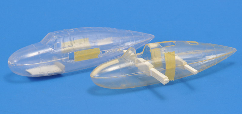
| I put the cast parts in the MPM box, and looked at them again after 20 months. The epoxy parts (front) had discolored a bit. Not enough to be a serious problem, but if the yellowing continues, it could become a problem.
| 
|
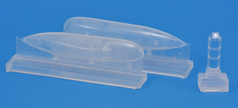
| Another lesson learned was that the sixth epoxy castings came out 'clouded', most likely due to mould deterioration. I've added another clear casting, cast from the same batch of clear epoxy, to show that the epoxy itself was OK.
I'm not really surprised: I had seen before that epoxy resin damages the moulds much more than polyurethane resin. I link it to the duration during which the resin is chemically active: 10 hours with this epoxy, 10 minutes with my polyurethane. With the latter I get 20 good castings, and now I know that with this clear epoxy I get 5 good castings.
|
While testfitting the modified fuselage between the wings, I had to sort out the wing dihedral. If a wing half is supported on the inboard section, the wingtip is about 5 mm high. This is not the usual way of measuring dihedral though! The drawing in part 1 of the Stichting Fokker G.I books, the dihedral is double, 10 mm. Judging from a head-on photo of a real G1, the drawing seems correct.
Other models
Five or six other Fokker G1 models in 1/72 scale have been identified. The resin models were issued under a number of brand names.
Model 1: Czech polyester model
In the IPMS-The Netherlands PIM-magazine 1979-3, member Ad Hendriks gives an account of organizing a 'Czech polyester model' (presumably 1/72) that he started two years earlier. He got in contact with the Czech individual, organized a good drawing together with Henk Kammerman, and after two months a first model was delivered. This was followed by more models: roughly a batch of ten arrived monthly. But unfortunately the deliveries stopped, apparently well before the 150 interested modelers were all served.
My modeling friend Eric Verschuur remembered the model from IPMS-NL meetings, where it was distributed. In his memory, the model had the wings, tailbooms, tailplanes and a partial fuselage cast as one part. The smaller parts were separate. The material was transparent or semi-transparent, an indication that indeed polyester casting resin was used for the production. Clear polyester resin was used at that time to embed objects in a clear blocks of plastic, so it was generally available. I don't remember polyurethane casting resin to be available back then.
Model 2: Rareplanes vac
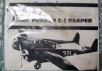
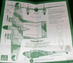
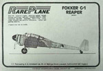
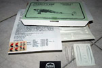
Rareplanes issued a vacform model in March 1978, as a bagged kit, possibly with catalog number 4011 (possibly it had no catalog number originally). The model has a much smaller fuselage pod than the MPM kit. I briefly studied it, and compared to the 1998 'Stichting Fokker G.I' drawings, the fuselage pod is 15% too narrow and 22% too low, but the length is more or less correct. Overall, the fuselage pod looks very small compared to the MPM pod. The same model was also issued in a flat cardboard box, with 'Produced by H.G. Hannant' text and catalog number RP4011. It had injection-moulded fuselage parts, of the same size as the original vacform parts. The vacform sheet with the fuselage parts is included too, but made of white plastic. It was possibly included for the seat parts on that sheet.
Model 3: Airmodel vac
Airmodel from Germany issued a vacform Fokker G.I, kit number 337. Peter Ibes reports that he built the model somewhere between 1990-1995, and he kindly supplied the following scans and information. The kit allowed construction of both the G.I Mercury (G.IA) and G.I Wasp (G.IB). The Mercury version could built using the integral wing+fuselage upper and lower halves, for the Wasp a separate fuselage pod was provided. White and pale green plastic card have been seen.
This model was reissued late 2009 with improved clear transparent parts, but still no decals or resin parts. Wheels, engines and props from a Frog/Novo or Airfix 1/72 scale Blenheim are recommended.
The Airmodel website has a photo showing the parts.
Model 4: planned model by Cap Croix du Sud
The IPMS-The Netherlands PIM-magazine 1979-5 contains a short article about the then-new company 'Cap Croix du Sud' that had just issued their first kit, a MiG-3. In a letter, the company explained that they were planning to produce 1939-1945 models that had not been issued so far. They were working on an IAR 80, Curtiss XP-55 Ascender, Fairey Fulmar, Fairey Albacore, Focke-Wulf Ta 154 and FW 187 and Arado 240. Regarding Dutch types, a Fokker G1 and a Fokker T VIII were planned, expected for October 1980.
Model 5: brandless Czech resin
A brandless resin G1 was produced by Czechoslovak modellers in the communist days and they were probably only used as trade material with pen-pals. Resin models of a Fokker D23 and a Fokker T8W were made by the same modelers. Fellow IPMS-NL member Jos Gouman owns two versions of the model, identified as on their plastic bages as 'Fokker G-1' and 'Fokker G-1 a/b' respectively. Jos describes them as cast as almost one-piece models with separate engine cowlings, props and landing gear parts, mostly of mediocre quality, and in case of the landing gear of insufficient strength. Cockpit and rear gunner position are vacuum formed parts, but the center fuselage windows are just represented as depressions to be filled with paint, or alternatively cut open and filled with Kristal Klear. The 'Fokker G-1 a/b' version has complete vacform fuselage halves (split horizontally) included as an extra, for which the resin fuselage must be removed. The engine cowlings also show differences: in some kits the engines are integral, in other the cilinders are separate. The meaning of the number '444' on the bag is not known. By the way, if you are interested in obtaining this model, please contact Jos Gouman, he has a few left over. Shown here are two of Jos' models.
Interestingly, the model has commonalities with the MPM model. The overall dimensions and shapes are identical, the horizontally split fuselage of the 'Fokker G-1 a/b' version is repeated in the MPM model, and the resin model's forward fuselage has the same shape problem as the MPM model. The Fokker T8W mentioned above also appeared as an MPM model, and it too has a lot of similarities. It is likely that the resin models served as masters for the MPM injection moulded models.
Likely the same model was offered on Ebay. The auction description mentioned "Rare CzechMASTER epoxy resin casting with detailed interior. Manufactured by my friend in Prague in the 1980s." Mysteriously, the single-piece casting now has two colors.
Model 6: Czech Masters Kits & IPMS Master Models & Aeromodell & Mareksa & Eurokit resin
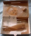
Czech Masters Kits issued a resin model in the mid-eighties (catalog number 74, with '72' hand-written below it). It is likely based on the brandless resin model, but it is broken down in parts. The same model was also sold from 1991 to 1994 by the 'IPMS-NL Shop' under their own label, IPMS Master Models, possibly without the instruction sheet. The model has a vacform fuselage pod that appears more accurate than the MPM fuselage, at least the windscreen of the cockpit is narrow as it should be. The left three model photos were made by Rene Erhart, the CMK instruction sheet and the right photo were provided by Sidney de Koning. The latter shows the better cockpit cross section and windscreen shape of the CMK model. Apart from the version shown here with parts in green resin, there is also a version with grey resin parts.
The same model was also sold by German mail order company WK Models under its Aeromodell brand with catalog number WK09, with both white, yellow and orange box labels. John Burns' PAK-20 book mentions "Many of the 1/72 resin-cast kits in the line probably came from Czechmaster molds". The G1 is clearly among these. Note the different resin color. Another model had green resin parts, and the cover sheet of the box was in yellow. Lastly, I've also seen a version which was 'packaged' in a printed yellow A4 sheet, folded double and stapled. Its parts were dark green.
Eurokit/Eurovac (earlier operating under the name Replica) sold resin models under the former name, and vacforms under the latter name. John Burns' PAK-20 book does not list the Fokker G1, but I found this one on Ebay. The small parts layout in the sheet of resin shows that this is again the same model. The parts are cast in yet another resin color.
John Burns' PAK-20 book also reports that the Polish manufacturer Mareska (in business between 1996 and 1998) issued a resin Fokker G1, and reports "Many (if not all) of these kits are also listed under Czechmaster and probably served as master molds for a variety of other European kit companies".
Aftermarket items
To replace the incorrect props, possibly Airfix Blenheim props or Aeroclub white-metal props will do the trick. I found two Aeroclub Blenheim props: P021, description '2x De Haviland (Hamilton-Standard) 3 blade 2 position bracket 11'6" [3.51 m] diameter R/H' for 'Bristol Engines - Blenheim/Beaufort' and P098, description '2x De Havilland two position BKT (bracket?) three blade 10' [3.05 m] diameter R/H' for the Bristol 142 which was a civil transport from which the Blenheim bomber was developed. The MPM props are 11'1" / 3.38 m. The Stichting drawings don't give a figure for them, but I measured 10'9" / 3.28 m in the drawings. Plenty of figures, take your pick!
Fellow modeler Jan Verwoerdt came up with the definitive answer to this question in June 2004: according to Fokker's G.I handbook (that was never issued to the LVA by the way), the Mercury VIII engined G.I had props with a diameter of 3.28 m, which translates into 10'9". Ten points for the Stichting drawings! But neither of the two Aeroclub props will be completely accurate. Later I found some NLL test reports, and they state a prop diameter of 3.30 m. For the 'G1 Wasp / G1B' a similar report quotes 2.715 m props, and the Hispano-Suiza engined prototype had 2.40 m props. In another NLL report that contains a table of available propellers, three-bladed De Havilland are listed with diameters of 2.90, 3.28, 3.96, 4.43 and 4.88 meters are listed.
Propeller news in 2014: SBS Model from Hungary issued resin propellers for the Airfix Bristol Blenheim (SBS catalog number 72022). They are possibly usable for the G.I.
The vast catalog of Aeroclub also contained several Bristol Mercury engines. Aeroclub is currently dormant, but a full list of engines can be found on Joe's Model site. It contains three Mercuries:
E071 1/72 Bristol Mercury engine and exhaust ring
E078 1/72 Bristol Mercury engine with Townend ring (resin)
E083 1/72 Bristol Mercury engine and cowling
Engine news in 2005: Vector
from Russia (Podolsk) issued a highly detailed and perfectly cast resin Bristol Mercury in both 1/72 and 1/48 scale. Linden Hill (USA) has a page with information, and the 1/48 engine was reviewed on Hyperscale. The 1/72 version is rather simpler than the 1/48: it just consists of a crank case plus gearbox and ten cilinders, and the cilinder lack the characteristic single pushrod tube. As with the MPM resin engines, the characteristic baffles are absent. Also, the 1/72 engines are labeled as 'Bristol Mercury/Pegasus', but the cilinders are those of the Mercury version, the Pegasus cilinders being much longer. The kit lacks instructions on assembly, painting and detailing.
Engine news in 2012: Radial Engines & Wheels 72 from the Czech Republic issued a resin 1/72 Bristol Mercury (72016). The engine is cast in one piece, in contrast to the separate cilinders and crankcase of the Vector engine. From a first photo the gearbox in front of the crank case looks better, and the cilinders have a pushrod tube and clear exhaust ports, which helps in getting the tubes to the exhaust collecter ring right. There's a brief review on the IPMS Germany site.
Engine news in 2014: SBS Model from Hungary issued a resin 1/72 Bristol Mercury in two different sets: 72015 for the Airfix Gloster Gladiator, and 72017 for the Airfix Bristol Blenheim (two engines). Each engine is cast in 22 separate resin parts. There's a review on Aircraft Resource Center.
Colors and markings
Probably the best source on the colors of the G.I is 'De geschiedenis van Camouflage en Kentekens op de vliegtuigen van de Nederlandse Strijdkrachten' by John Greuter, Max Schep, Luc Boerman and Joke Bossong, Bonneville, 1997. This book reports that no paint chips survive, only some models that were painted at the Fokker factory with the original paints. These give a reasonable idea of the colors. The G.I was painted brown overall with sand and green patches on the top surfaces. There was one scheme, but in two variations, with the green and sand switched (used on 300-317 and 318-335 respectively). The following matches are reported:
Camouflagebeige (beige): FS -6360 (Xtra X16, Humbrol 168)
Camouflagegroen (green): FS -4077 (Xtra X223, Humbrol 172)
Camouflagebruin (brown): FS -0059 (no matches given, but Humbrol 10 looks like a reasonable match to me, but 10% too dark)
Another interesting source of G.I colors was published in 'Periodiek Informatie Bulletin (PIM)' by IPMS-NL, issue 1983-5. In a letter by P. van de Dijk from Utrecht, he recalls the colors he saw on LSK aircraft before the war at Soesterberg. Working from memory, but having tested his memories on Fokker D21 and G.I models, this modeler reports:
Sand: FS 20118 - 20277 (Humbrol HB-12 Mid Stone) - FS 20118 is much darker than 26360, FS 20277 is reasonably close but browner
Groen: FS 24102 (Humbrol HI-1 Mottle Green) - lighter than FS 24077
Bruin: FS 20045 (Humbrol HF-6 Chocolat) - this agrees well with FS 20059
The MPM instructions suggest the following colors:
Tan: FS 30257 (Humbrol 63)
Dark Green: FS 34138 (Humbrol 131)
Dark Brown: FS 20100 (Humbrol 133 + Humbrol 62, 70:30 mix)
A different set of matches was found on rec.models.scale, posted by Jim Maas in 1997. It's colors are somewhat closer to the first set of matches, compared to the MPM colors:
Tan: FS 33448/30318 neighborhood
Dark Green: FS 34128 (has a blue tinge)
Dark Brown: FS 20100 (but flat)
I am a long way from the painting stage, and I haven't studied the FS matches in detail yet. On first inspection, the first set of colors is rather different from the other two sets. The green is very dark, the sand is not a tan color (it has little yellow in it, and a bit of green), and the brown has much less red in it. The model's appearance will be quite different from the MPM and Jim Maas colors, and very different from the MPM box art or the book cover shown above. The cockpit color is not confirmed yet, but nearly everything points to light grey. Other Fokkers from that era also used that color, and cockpit pictures show a light color. I will use light grey with very few doubts.
In March 2005, White Ensign Models announced that it will produce the G.I (and D21) colors for MW Models in the Netherlands, now Naval Models but the site doesn't list the paint. The colors are coded as follows: ACD 01, LVA Camouflage Groen (green gray), ACD 02, LVA Camouflage Bruin (dark brown), and ACD 03, LVA Camouflage Beige (light sand). Luchtvaart Hobby Shop started selling them in 2005. Here's a message from White Ensign Models about the paint.
A couple of days after I bought the White Ensign Models paints, *possibly* a spanner was thrown in the works. According to a member of the Stichting Fokker G.I, the colors found on recovered G.I parts was different from those reported in the 'Camouflage en Kentekens' book. He wasn't completely sure though, but I found it worth mentioning here.
Decals
I haven't looked good at the MPM decals, so I can't say whether they are correct. For aftermarket decals, there are/were two choices:
IPMS-NL 'Decalset 3: Letters/cijfers van de Luchtvaartafdeling & Marineluchtvaartdienst 1920-1940', issued in 1988. The set consists of four A5 sheets, with 'curly' and 'square' white numbers for various LVA aircraft, 'square' black numbers for MLD aircraft, an orange area to cut triangles from, black stripes for the borders, nose art in the shape of 'drie witte muizen / three white mice' and 'puntschoen / pointy shoe' for the D.XXI and 'eend met knoop in de nek / duck with knot in neck' for the G.I, and lastly white stencils for the G.I tailboom (unreadable). Design was by Luc Boerman (Mr Dutch Decal) with text by Hans Berfelo
Dutch Decal sheet 72030, with decals for the Fokker D-XXI, Fokker G-1, Kingfisher and Buffalo, issued around 1995/1996 I think. It is out of production, but the Stichting Fokker G.I is reported to have quite a few sets for sale.
In 2015,
Kora Models issued three 1/72 Fokker G1 sheets: Fokker G1A "Faucheur" Dutch service (DEC72319), Fokker G1A "Faucheur" (Luftwaffe Service) Part 1 (DEC72320) and Fokker G1A "Faucheur" (Luftwaffe Service) Part 2 (DEC72321)
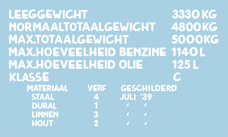
| I designed some decals myself using CorelDraw, for Alps printing. Apart from the serial numbers I want, I made a decal for the data block seen on the tail boom of most G.I's. This decal is not included on the MPM sheet, and only partially and unreadable on the Dutch Decal sheet. It took lots of modifications on an existing font to make something that looked like a hand painted 1939 font, but I think it looks really sweet now. Only problem is that I hadn't realised how small the printing would be. It is to be seen whether my sweet data block is readable in 1/72 scale.. Some of the figures in the data block are guestimates! Also, my interpretation of the wording differs in detail from that of Jan Broos in the NVM drawings. I used 'Benzine' instead of 'Brandstof' and 'Geschilderd' instead of 'Datum'.
| 
|

| Shown here are the actual decals. Their quality may look mediocre, but remember how small the lettering is: only 0.25 mm (1/100th of an inch) high, and still readable! I had to scan the decals at no less than 1200 dpi to show it, and then crank up the contrast and reduce the brightness to make them better visible. This explains the spotty background color. Alps decals are fantastic!
|
Bristol Mercury engines
To reduce the loading time of the current page, I moved the reference photos and drawings of the Mercury engine to a separate page: Bristol Mercury engine of the Fokker G.I.
Fellow G1 builder Sander van Kreijl provided this photo of the built-up resin engine as supplied with the 'upgraded' version of the MPM kit. It consists of a crankcase with individual cilinders. Not included are the prominent valve pushrods (running in black oval cross section housings) and the white baffles between the cilinders.
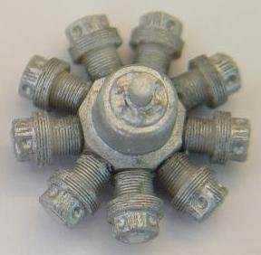
One could also take a ToRo Models (Poland) 1/48 resin Mercury (catalog number 48001) for inspiration.
Fokker G1 Hispano-Suiza / Wasp / Mercury dimensions
Spurred by the discovery of the W.A. Wylam Fokker G1 Wasp drawings in the American magazine '(Universal) Model Airplane News', August 1943 issue, I started to get interested in the Wasp version of the Fokker G1. I decided to make an overview of the dimensions of all three versions. This opened quite a can of worms, even for the Mercury version. Two dimensions have conflicting data: the length of both the Hispano-Suiza and Mercury versions, and they are highlighted. Also of interest to the model builder is the fuselage length difference between the Waps and Mercury versions (highlighted).
| Dimension
| prototype with Hispano-Suiza
| production Wasp
| production Mercury VIII
| Notes
|
|
|
|
|
|
|
|
|
|
| Span (m)
| 16.50
| GKOV p28 (Fokker drawing)
| 16.52
| Hoo p190
| 17.16
| GKOV p108
|
|
|
| 16.50
| GKOV p64
| 16.50
| Hoo p195 (ML manual)
| 17.16
| GKOV p219 (Fokker report)
|
|
|
| 16.50
| GKOV p108
| 16.52
| Heg p195
| 17.16
| GKOV p242 (ML report)
|
|
|
| 16.50
| GKOV p111 (Fokker report)
|
|
| 17.16
| Hoo p194 (ML manual)
|
|
|
| 16.52
| Heg p194
|
|
| 17.16
| Heg p195
|
|
|
|
|
|
|
|
|
|
|
| Length (m)
| 10.38
| GKOV p28 (Fokker drawing)
| 10.38
| GKOV p108
| 10.87
| GKOV p108
| GKOV p43 says 300 mm extra length in the tailbooms added for the Wasp version. I have some doubts, since the November 1936 Fokker brochure says 10.38 meters, and Wylam measured the same on a Wasp G1 in the UK
|
|
| 10.08
| GKOV p108
| 10.38
| Hoo p195 (ML manual)
| 11.50
| GKOV p111
|
|
|
| 10.30
| GKOV p111
| 10.33
| Heg p195
| 10.84
| GKOV p120
|
|
|
| 10.33
| Heg p194
|
|
| 11.50
| GKOV p219 (Fokker report)
|
|
|
|
|
|
|
| 11.50
| GKOV p242 (ML report)
|
|
|
|
|
|
|
| 10.87
| Hoo p194 (ML manual)
|
|
|
|
|
|
|
| 11.55
| Heg p195
|
|
|
|
|
|
|
|
|
|
|
| Engine distance (m)
| 4.00
| GKOV p108
| 4.00
| GKOV p108
| 4.63
| GKOV p108
|
|
|
|
|
| 4.00
| Hoo p195 (ML manual)
| 4.63
| GKOV p242 (ML report)
|
|
|
|
|
|
|
|
|
|
|
| Prop diameter (m)
| 2.40
| GKOV p60
| 3.10
| GKOV p108
| 3.28
| GKOV p108
| GKOV p43: prop to fuselage distance minimal on Wasp version
|
|
| 3.10
| GKOV p108
|
|
| 3.28
| Hoo p194 (ML manual)
|
|
|
|
|
|
|
|
|
|
|
| Wing area (m2)
| 35.7
| GKOV p60
| 35.7
| GKOV p111
| 38.3
| GKOV p111
|
|
|
|
|
| 35.7
| Hoo p195 (ML manual)
| 38.3
| Hoo p194 (ML manual)
|
|
|
|
|
|
|
|
|
|
|
| Center section chord (m)
|
|
| 2.74
| Wylam
| 2.75
| GKOV p242
|
|
|
|
|
|
|
|
|
|
|
| Tip chord (m)
|
|
| 1.33 ?
| Wylam
| 1.50
| GKOV p242
| definitions probably differ
|
|
|
|
|
|
|
|
|
|
| Fuselage length (m)
|
|
| 6.30
| Wylam, if I read 20'8" correctly
| 6.65
| GKOV p121
| GKOV p109 says Hispano-Suiza and Wasp version have a shorter nose
|
|
|
|
|
|
|
|
|
|
| Fuselage height (m)
|
|
|
|
| 1.665
| GKOV p128
|
|
|
|
|
|
|
|
|
|
|
Hispano-Suiza and Wasp G1s had parallel wing spars, like all older Fokker designs. Mercury G1 had a straight front spar, and a swept-forward rear spar.
Tire sizes in GKOV p242
|
References:
GKOV: Fokker G-1 Deel 1, Frits Gerdessen, Karel Kalkman, Cor Oostveen and Willem Vredeling, 2011
Hoo: Fokker G-1 / Het verhaal van onze mooiste jachtkruiser / Nederlandse Vliegtuigen Encyclopedie, Hugo Hooftman, 1977
Heg: Fokker: The man and the aircraft, Henri Hegener, 1961
Wylam: Fokker G1 Wasp drawings in the American magazine '(Universal) Model Airplane News', August 1943 issue. Drawings also sold separately by Model Airplane News. These drawings were most likely drawn by W.A. Wylam while stationed in the UK, where he had the opportunity to study G1 Wasp '362' that had fled from the Netherlands. I've got a not-so-good scan or copy of the drawings, making the dimensions hard to read.
|
Modeling links
Links
Return to models page


