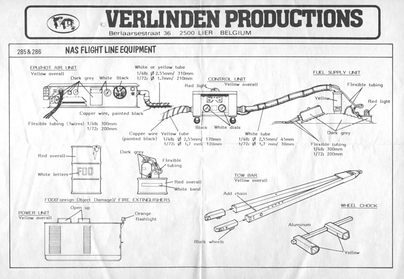
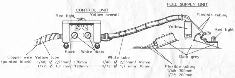
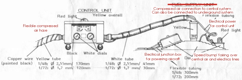
Verlinden 1/72 NAS flight line equipment


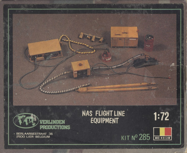
I had looked for this out-of-production Verlinden set before, but the usual asking price of 25+ euros for just a few parts put me off. But then I found it for 2 euros at the 2024 KMK Mol show in Geel, together with three other Verlinden US Navy sets. I first thought they were selling empty boxes for that price.

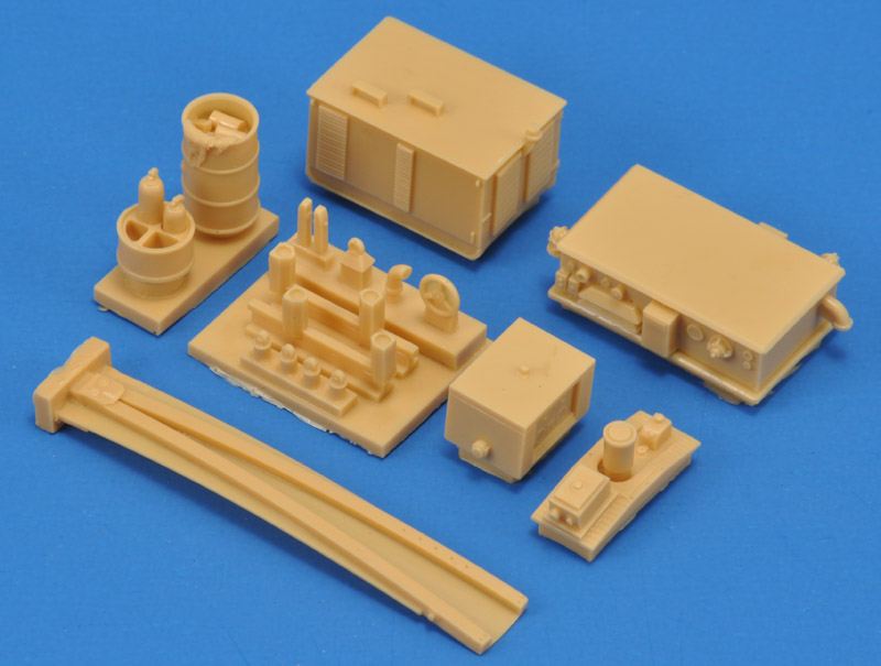
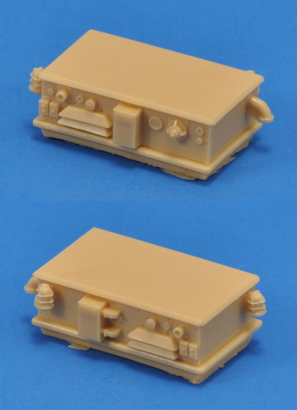
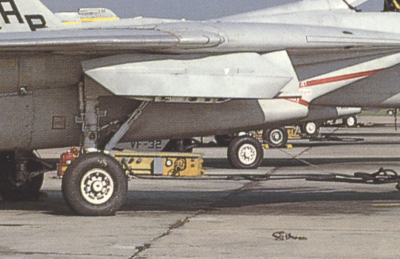
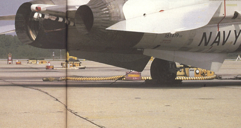
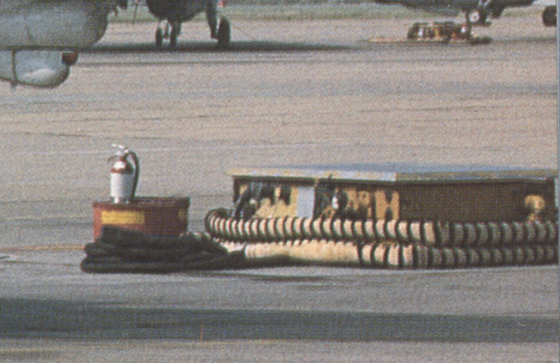
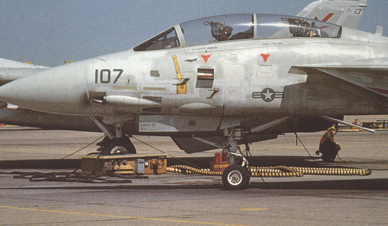
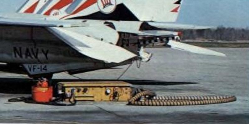
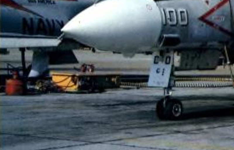
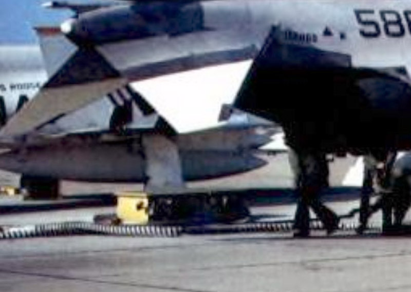
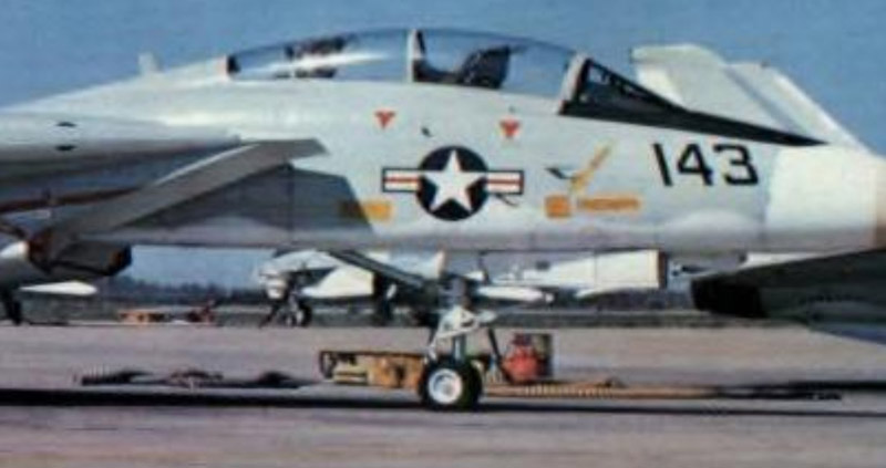
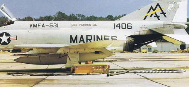
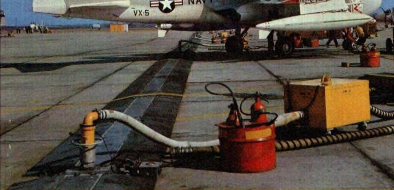
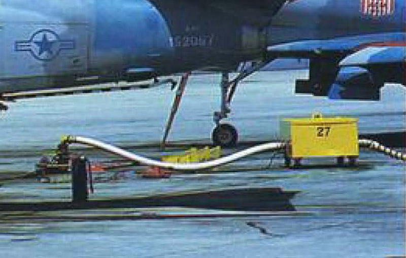
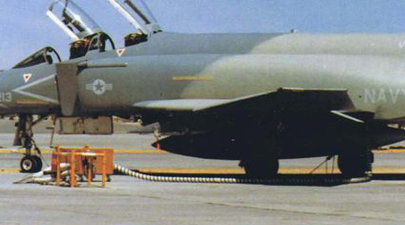
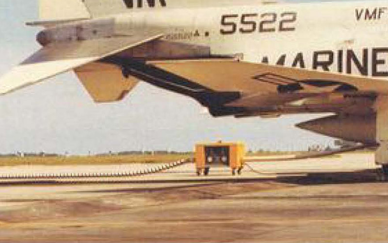
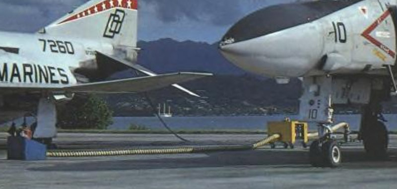
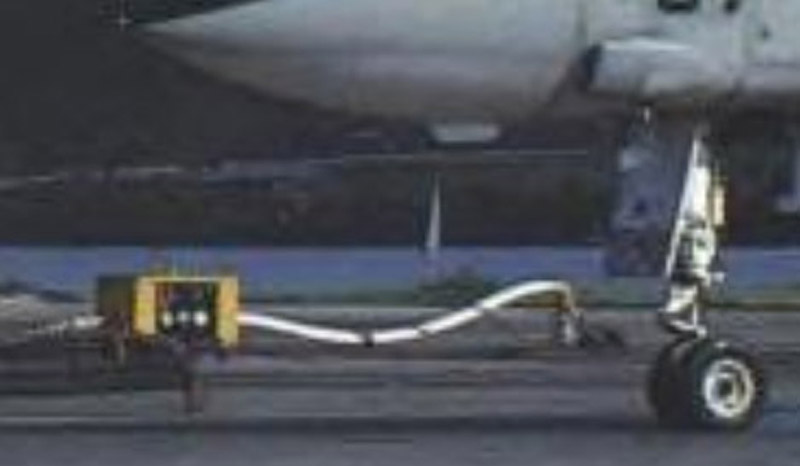
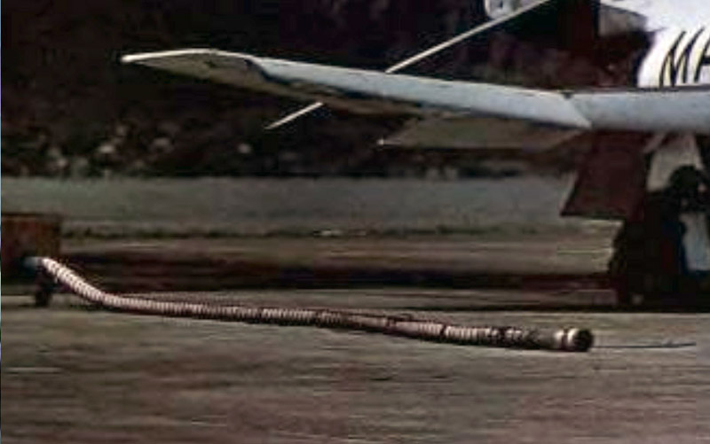
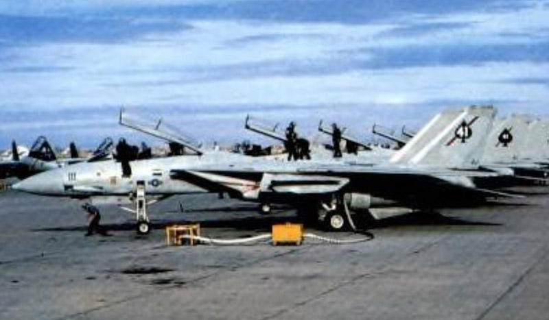
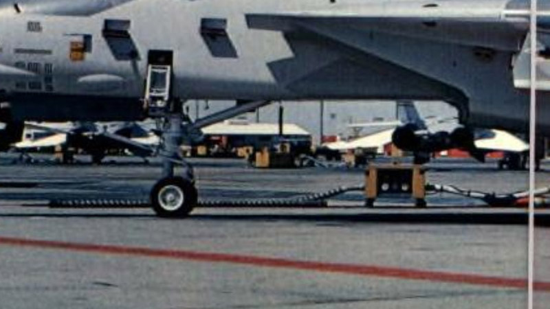
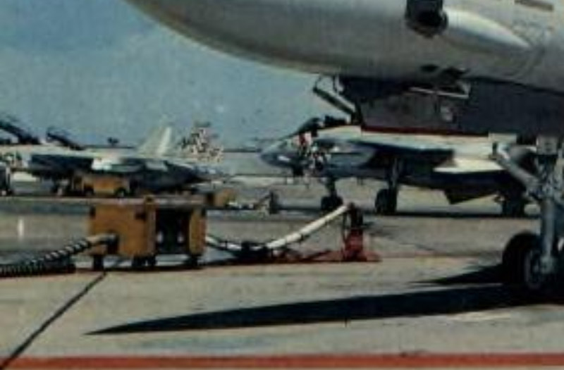
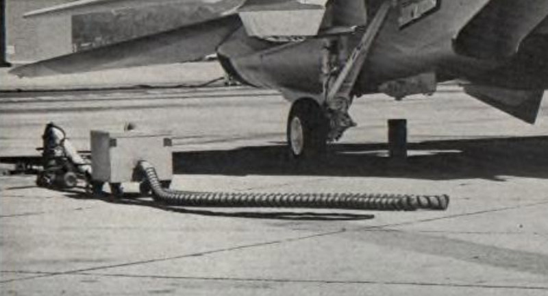
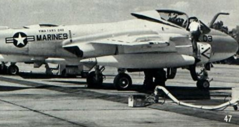
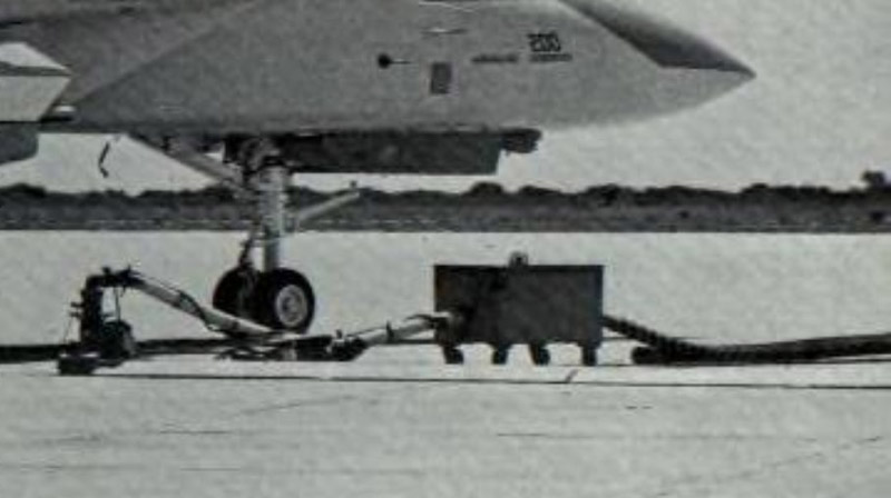
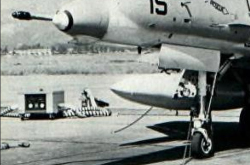
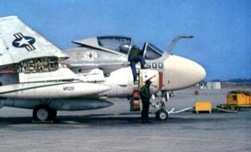
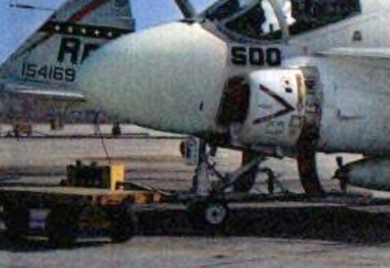
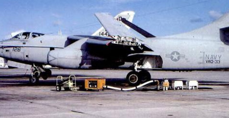
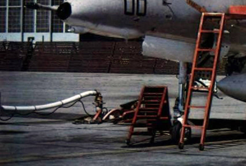
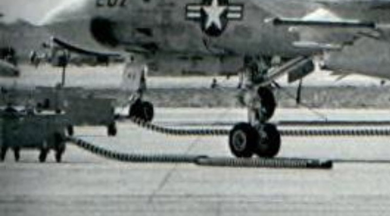
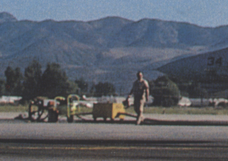
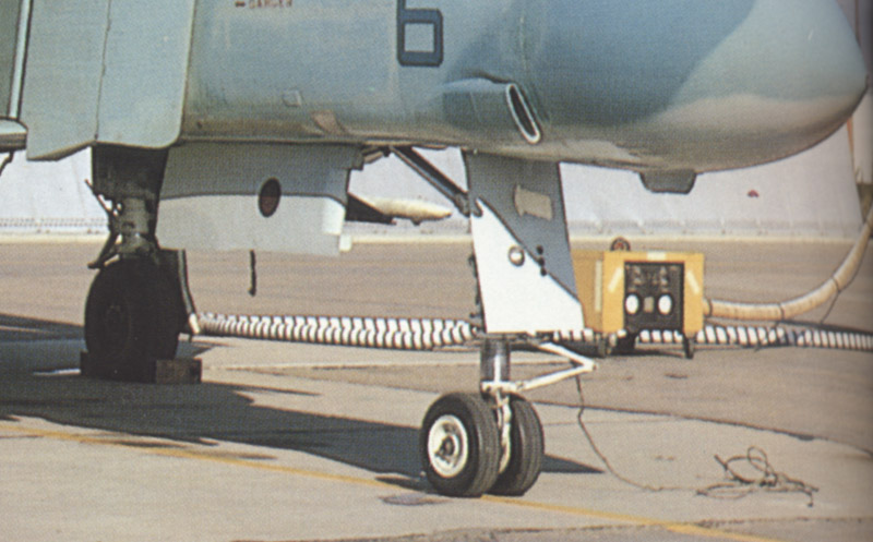
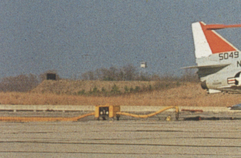
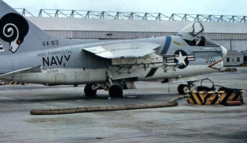
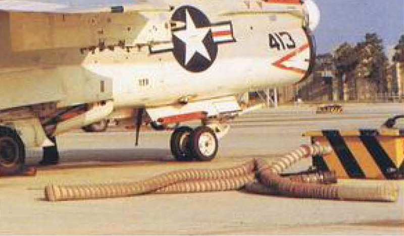
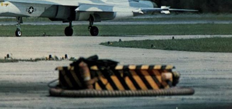
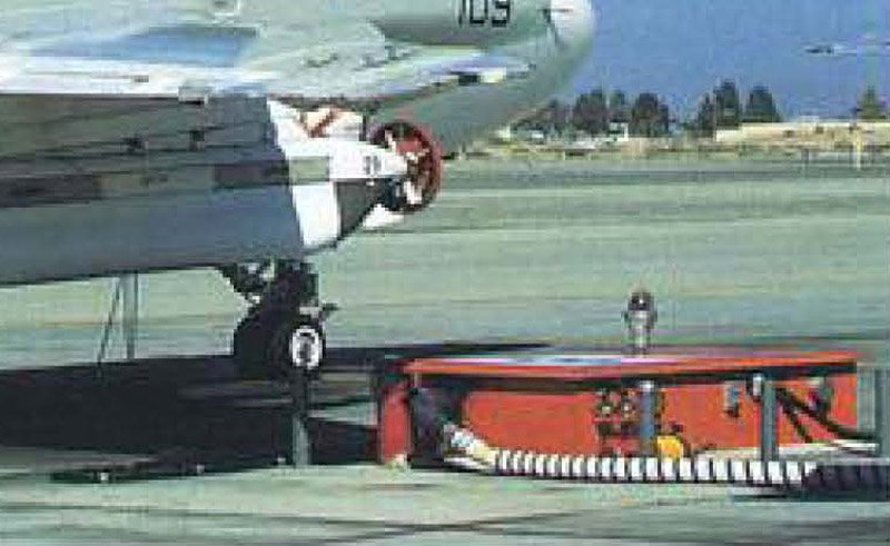
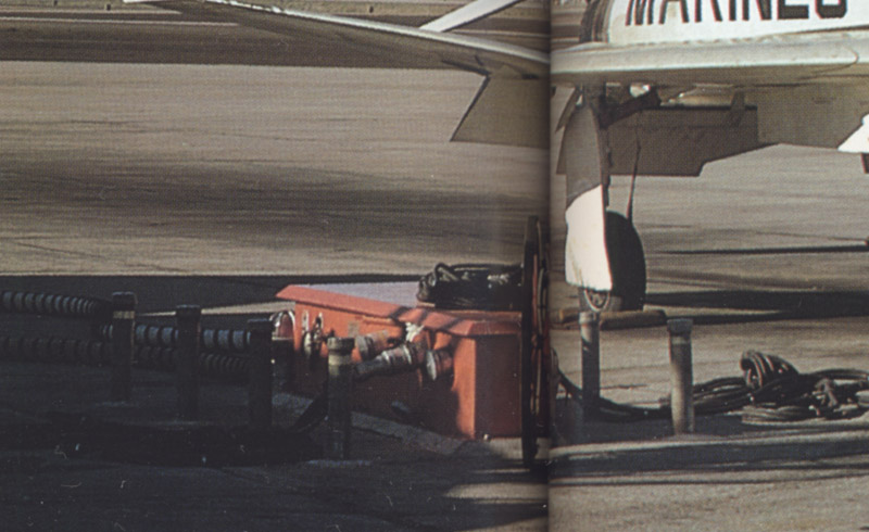
Knowing the creative freedom that Verlinden sometimes allowed themselves, I then went looking for photos of the real thing. And I was pleasantly surprised that the parts are quite accurate. I think they are great diorama accessories.


The kit

The kit has catalog number 285. There's a 1/48 version too, with catalog number 286. The parts are perfectly cast, as usual with Verlinden, except for the towbar that was quite deformed.

I found a grand total of one online report of a diorama that used the 1/48 set (see links section). It looks like it wasn't very popular.
Plastic and rubber hoses are also included.
A scan of the instruction sheet. As usual with Verlinden, it leaves open lots of questions, like how to paint the other sides.
Here's an identification of all resin parts:

A: unknown (called 'Power unit' in instructions)
B: Stationary air starter & electric power unit
C: FOD bin / garbage can (former oil drum)
D: cut down oil drum for two fire extuingishers
E: end pieces for town bar M
F: possible tow bar ring for tow bar M
G: 90° elbow for mounting on top of the 'speed bump' connector
H: wheel for services box B
I: two wheel chocks
J: four wheels for box K
K: movable air starter box
L: 'speed bump' connector, used with box K
M: tow bar (bent)

I found several photos of units B and K, but none of A.


Stationary air starter & electric power unit (part B)

The resin part has details on all four sides. Those shown at the top photo correspond to the photos shown below, and the instruction sheet shows how the detail and paint that side. The details shown at the bottom photo however do not appear in the photos shown below, and are not explained on the instruction sheet.

ARC forum member GW8345 reported that the Verlinden part, with details on either side, is the eighties configuration, and the photos below are the seventies configuration, with details on one side. He also reported that the 'dog houses' were re-worked and/or upgraded every ten-ish years.
Based on the photos shown, the following comments can be made:
  • the four-spoke wheel (three spokes in the kit, part H) attaches where the instruction sheet shows it. It sticks out a good end

  • the 'mailbox' is light gray

  • the three thin wires, to be connected on the left of the front side, are for the 3-phase electrical power for the aircraft

  • the compressed air hose fits to the elbow pipe, pointing down, on the right side

  • there are two red marker lights, to prevent vehicles running into the box in the dark

  • none of the photos below shows the lower flange of the box

  • the photos don't allow a dimensional check, since the boxes and the aircraft are at an angle to each other. The boxes are placed perpendicular to the taxiway, but the flightline's parking spot are at ~30 degrees to the taxiway

At least the following airfields had this type of stationary air starter & electric power unit: NAS Oceana (boxes were yellow), NAS Miramar and NAS Cecil Field in the late eighties / early nineties; MCAS Yuma in the 1992-1993 bracket.

This photo shows one detail projecting from the 'rear' face of the box, but it's difficult to see what it acutally is.

Source: 'Tomcats forever', David Brown & Robert Dorr. Oceana 1982.
This photo shows two details projecting from the 'rear' face of the box.

Source: 'Tomcats forever', David Brown & Robert Dorr. Oceana 1981.
Oceana 1979

Source: 'Tomcats forever', David Brown & Robert Dorr.
Oceana 1982

Source: 'Tomcats forever', David Brown & Robert Dorr.
Oceana 1989

Source: 'Tomcats forever', David Brown & Robert Dorr.
No location listed.

Source: 'Tomcats forever', David Brown & Robert Dorr.
NAS Oceana photo. The 'letterbox' is either painted yellow, or absent - it's difficult to see. There's no shadow to be seen.

Source: Koku Fan 1976-08, see 'Bunrindo Koku Fan' on Internet Archive.
No location listed.

Source: Koku Fan 1972-06, see 'Bunrindo Koku Fan' on Internet Archive.
No location listed.

Source: Koku Fan 1972-06, see 'Bunrindo Koku Fan' on Internet Archive.
NAS Oceana photo.

Source: Koku Fan 1972-06, see 'Bunrindo Koku Fan' on Internet Archive.
The only photo so far that shows the 'back' side of the Verlinden part B. The 'letterbox' is missing.

Source: Official Monogram US Navy & Marine Corps Aircraft Color Guide Volume 4 1960-1993, page 123


Movable air starter box (part K)

Based on the photos, the following comments can be made:
  • this box provides only compressed air to the aircraft, for engine starting

  • the box provides no electrical power to the aircraft, but the box itself is electrically powered. Otherwise the red light wouldn't work, for example.

  • the 'fuel supply unit' in the instructions is misleading. The 'speed bump' contained housed high-pressure air piping and electrical power lines. There was a high pressure air plant and air storage tanks on the side of the flight line.

  • some photos show the air starter box connected to underground high pressure air piping, instead of a 'speed bump'.

  • the tilted box on the left side of the 'speed bump' is an electrical power junction box, that provides electrical power to the aircraft to be started.

Here's the instruction sheet picture with several corrections. Hopefully this makes the working of this unit clear.

On the ARC Forum, member GW8345 mentioned that the three-phase electrical cable to power the aircraft could be three separate wires, or one thick cable of 2~2.5 inch diameter. He also mentioned that the cable was either plugged into the aircraft or coiled up neatly - there was no in between.

The following airfields are reported to have used these boxes in the eighties: NAS Miramar, NAS Fallon, NAS Cecil Field, NAS Patuxent River, MCAS El Toro, MCAS Kaneohe Bay and NAWS China Lake. Of course there could be more.
This resembles the kit's details very closely. Note the length of the 'speed bump' fairing. The VX-5 Intruder makes it NAWS China Lake.

Source: Koku Fan 1972-06 cover, see 'Bunrindo Koku Fan' on Internet Archive.
This mobile box is also connected to an underground compressed air system. The connection point appears to be protected by a low tubular 'fence'. Location not mentioned in photo caption. VF-171 det Key West A-4 Aggressor.

Source: Official Monogram US Navy & Marine Corps Aircraft Color Guide Volume 4 1960-1993, page 90
VF-302 F-4S. It's not very clear, but it looks like the mobile unit connects to an underground pipe, and the connector is protected by a steel tube frame. Location not mentioned in photo caption.

Source: Official Monogram US Navy & Marine Corps Aircraft Color Guide Volume 4 1960-1993, page 167
VFMA-451 VM-12 F-4. Location not mentioned in photo caption.

Source: Official Monogram US Navy & Marine Corps Aircraft Color Guide Volume 4 1960-1993, page 129
MAS Kaneohe Bay, Hawaii. It's difficult to see, but it appears that there is a 'speed bump' fairing.

Source: Koku Fan 1978-09, see 'Bunrindo Koku Fan' on Internet Archive.
MCAS Kaneohe Bay, Hawaii, again.

Source: Koku Fan 1978-09, see 'Bunrindo Koku Fan' on Internet Archive.
MCAS Kaneohe Bay, Hawaii, but the aircraft is seen from the other side.

Source: Koku Fan 1975-07, see 'Bunrindo Koku Fan' on Internet Archive.
Identified as NAS Fallon. Here the system connects to undergound compressed air piping.

Source: Koku Fan 1981-08, see 'Bunrindo Koku Fan' on Internet Archive.
NAS Miramar.

Source: Koku Fan 1976-07, see 'Bunrindo Koku Fan' on Internet Archive.
NAS Miramar.

Source: Koku Fan 1976-07 cover, see 'Bunrindo Koku Fan' on Internet Archive.
NAS Miramar.

Source: Koku Fan 1976-06, see 'Bunrindo Koku Fan' on Internet Archive.
Location unknown.

Source: Koku Fan 1975-09, see 'Bunrindo Koku Fan' on Internet Archive.
NAS Miramar.

Source: Koku Fan 1976-06, see 'Bunrindo Koku Fan' on Internet Archive.
Location unknown.

Source: Koku Fan 1975-08, see 'Bunrindo Koku Fan' on Internet Archive.
Location unknown.

Source: Koku Fan 1972-06, see 'Bunrindo Koku Fan' on Internet Archive.
Location unknown.

Source: Koku Fan 1972-06, see 'Bunrindo Koku Fan' on Internet Archive.
Possibly NAS Key West in the mid to late 80's.

Source: Koku Fan 1991-09, see 'Bunrindo Koku Fan' on Internet Archive.
MCAS El Toro.

Source: Koku Fan 1975-08, see 'Bunrindo Koku Fan' on Internet Archive.
NAS Miramar

Source: Koku Fan 1979-03, see 'Bunrindo Koku Fan' on Internet Archive.
Location unknown.

Source: Koku Fan Illustrated No 36 'F-4 Phantom'
Location unknown.

Source: Koku Fan Illustrated No 36 'F-4 Phantom'
Patuxent River, 1975

Source: 'Tomcats forever', David Brown & Robert Dorr.


Another model stationary services box - 1

Identified as NAS Cecil Field. This box appears to be slightly taller, or it's smaller with the same height. It has no louvers.

Source: Koku Fan 1973-04, see 'Bunrindo Koku Fan' on Internet Archive.
This looks like the same unit. The compressed air hose exits from the same location, and it also shares the small silvery pipe at the opposite corner. No location is mentioned.

Source: Official Monogram US Navy & Marine Corps Aircraft Color Guide Volume 4 1960-1993, page 126
The caption says it's NAS Cecil Field

Source: Koku Fan 1975-09, see 'Bunrindo Koku Fan' on Internet Archive.
The caption says it's NAS Cecil Field.

Source: Koku Fan 1975-09, see 'Bunrindo Koku Fan' on Internet Archive.


Another model stationary services box - 2

This box has different details, and lacks (among others) the large wheel for air pressure control. There are protection poles around the box.

Source: Official Monogram US Navy & Marine Corps Aircraft Color Guide Volume 4 1960-1993, page 146
This is probably the same type, but painted yellow. Among others, the attachment of the air hose is in the same position. It has concrete 'speed bumps' as protection.

Source: Official Monogram US Navy & Marine Corps Aircraft Color Guide Volume 4 1960-1993, page 144
Probably the same type of services box as in the first photo. The lid / roof is clearly chamfered.

Source: Koku Fan Illustrated No 36 'F-4 Phantom'.


Links


Return to models page