| Many modelers struggle to find a decent spray booth. Many cheap commercial spray booths use computer fans with very limited power, that most likely have a very limited air flow. Add a long flexible hose, and it gets even worse.
Using various references, I put together a method to calculate whether your fan is strong enough. However, you need detailed information on the fan, and that information is usually lacking. In the end, the analysis became quite involved, and probably too much work for the average modeler. But I had started the analysis, and wanted to know the answer.. |
If you don't want to work your way through the information presented below, here's the easy answer: buy or build a paint booth with sufficient blower power, say 50 Watt. Don't buy a cheap paint booth with a 10 Watt computer fan.
The required air flow of a spray booth can be calculated quite easily. The American OSHA Criteria for design and construction of spray booths states in section 66(b)(5)(i) that "average air velocity over the open face of the booth shall be not less than 100 linear feet per minute". My current booth is roughly 30 x 40 cm, or 0.12 m2. I convert 100 ft/min to 30 m/min. 30 x 0.12 gives 3.6 m3/min, or 60 liters/second. I think a large garbage bag is 70 liters, so it sucks that empty in one second - that's a considerable volume I would say!
As for measuring the actual air speed of your spray booth, a handheld anemometer from the meteorology and the sailing sport is probably the simplest solution.
In the February 1992 and December 2000 Fine Scale Models articles, it is stated that the OSHA recommendation is 100 to 200 feet per minute. I checked the official document but could not find the 200 feet per minute number anywhere. However, I do agree that OSHA states that 100 feet per minute is the minimum, and that a bit extra cannot be bad.
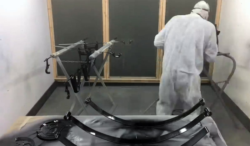
We do have to keep in mind that the OSHA requirements are geared to industrial spray booths, something like this:
Using the webpage Spray booth design and fan selection by Klaus Raddatz (also published on Modelersite), you can calculate the drag of the exhaust ducting, that the fan has to fight against, and what reduces the air flow considerably. The drag is called 'static pressure', the overpressure required to overcome the drag.
I calculated the static pressure for my own set-up. It has 100 mm diameter flexible ducting, equaling the 4" ducting on the webpage. In its current, non-optimised layout, it has a 4.3' and a 1' straight section, plus six 90 degree turns. This gives a fictitious total length of 4.3' + 1' + 6 x 6' = 41.3', to be multiplied by 3 for the flexible ducting, making 124' effective length.
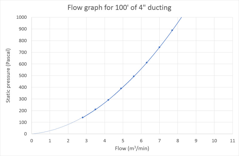
To achieve the required flow of 3.6 m3/min, as calculated above, Klaus Raddatz' static pressure table shows for 4" ducting and 125 CFM a static pressure of 0.84 inches H2O, per 100' of smooth duct. 0.84 H2O times 124'/100' makes 1.04 inches H2O. In SI units this is 26 mm H2O = 260 Pascal. You could conclude that a blower is required that has a flow of 3.6 m3/min at a static pressure of 260 Pascal. But that's not how it actually works, the correct procedure is shown below.
If I would optimise the ducting, by removing four of the 90 degree turns, and switch to smooth ducting, I would have a fictitious total length of 4.3' + 2 x 6' = 16.3'. Static pressure would drop to 16.3'/100' times 0.84 H2O, which makes 0.14 inches H2O (3.6 mm H2O, 36 Pascal), just 13% of the current value.
Note that one thing is missing in the static pressure analysis: the drag of the filter. I have no idea (yet) where to find that information.
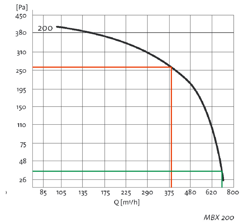
I obtained a well-used 'Itho boxventilator MBX200', formerly used in a building to ventilate four small apartments. I found its flow graph, shown here:
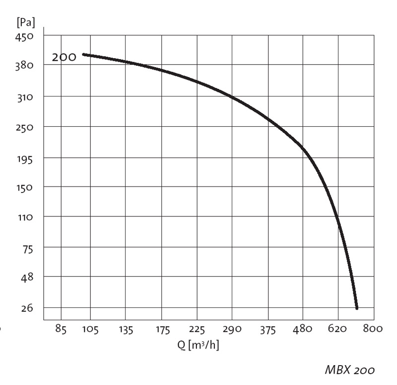
A bit of work is required to calculate the actual flow resulting from my ducting. Firstly, the gridlines of the MBX200 graph are very weird, and they had to be replotted linearly, changing units from m3/hr to m3/min. Secondly, I had to rework the data from Klaus Raddatz' webpage for 100' of 4" ducting into an equation linking static pressure to flow, in SI units:
static pressure (Pascal) per 30.5 meters = 13.09 * flow^2 (m3/min) + 14.48 * flow (m3/min)
The graph plot shows that more and more pressure is needed to increase the flow, for a giving duct. The effect is not linear.
To calculate the flow characteristics of my two ducting solutions, I had to multiply the equation above by 1.24 (124' effective length divided by 100' reference length) and 0.163 (16.3' effective length divided by 100' reference length) respectively, giving:
current ducting: static pressure (Pascal) = 16.23 * flow^2 (m3/min) + 17.96 * flow (m3/min), plotted in red below
much improved ducting: static pressure (Pascal) = 3.13 * flow^2 (m3/min) + 2.36 * flow (m3/min), plotted in green below
Lastly, all three graphs were combined. The intersections of the lines show that my current ducting would give me 4 m3/min with a static pressure of ~330 Pascal, and the much improved ducting would result in a flow of 8 m3/min with a static pressure of ~220 Pascal.
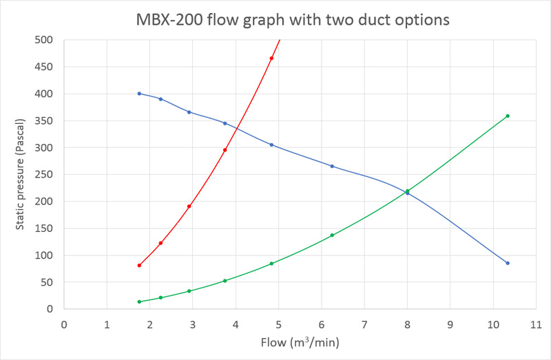
The incorrect way of using the flow graph is shown below. Here the values of 260 and 36 Pascal, calculated earlier from a desired flow, were simply used to look up the flow, giving 6.4 m3/min and 11.7 m3/min respectively. Both answers are wrong.
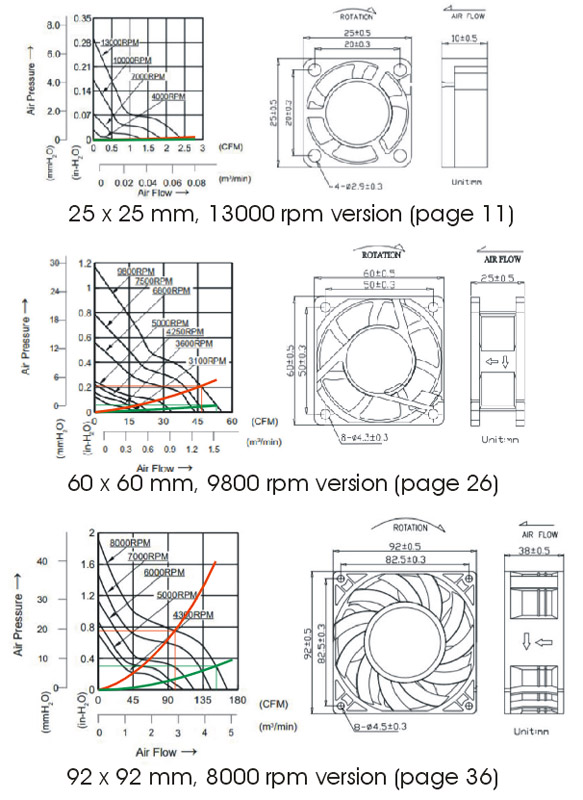
Some DIY and commercial spray booths use computer fans. I studied the product catalog of a random brand of computer fans: Wakefield-Vette, and used it to make the picture below. Note that the vertical scale is in mm H20, not Pascal. I plotted the flow equations for the current ducting in green, and the much improved ducting in green.
the smallest fan, 25 x 25 mm, 13000 rpm version (page 11), achieves around 0.065 m3/min in both cases - 1/55th of the desired 3.6 m3/min. The flow is so small that it experiences hardly any drag in the exhaust ducting.
the medium-sized fan, 60 x 60 mm fan, 9800 rpm version (page 26), achieves around 1.25 m3/min and 1.5 m3/min respectively.
the most powerful fan, judging by power, is a 92 x 92 mm, 8000 rpm version (page 36), achieves around 2.9 m3/min and 4.4 m3/min respectively. Power consumption would be 35 Watts.
My conclusion is that a large computer fan (or fans) might work, despite my earlier doubts.
To start combustion, the concentration of a flammable vapor should be between that vapor's LEL (Lower Explosion Level) or LFL (Lower Flammability Limit), and the Upper Explosion Level (UEL) or Upper Flammability Limit (UFL). Below the LEL/LFL, the mixture is too lean to burn, above the UEL/UFL the mixture is too rich to burn. It is expressed as percentage in volume of the vapor, not the volume of the liquid. Wikipedia has a long list of flammability limits. The Material Safety Data Sheet (MSDS) of a product also contains this data.
I made two sample calculations, with an assumed spray booth flow of 100 CFM, 47 liters/second. The assumption of 1 ml of thinner per second is a guess, but I don't think I can spray so much paint + thinner in such a short time, using a typical modeler's airbrush.
again a bit of an assumption: I understand most of the thinner in MRP paint is acetone. 1 ml of liquid acetone weighs 0.78 grams. Its vapor density is ~2 times that of air - I calculate 2.45 grams/liter. Therefore 0.78 grams makes 0.32 liters of vapor. If this volume is sprayed in 1 second, the concentration is 0.32 / 47 = 0.7%, well below 2.6-3% listed as LEL/LFL.
Iso-Propyl Alcohol (IPA) is a popular thinner for acrylic paint. Its LEL/LFL is 2%.
Just maybe, there are thinners that have a much lower LEL, so don't take the above examples as the general truth.
It is often stated that an explosion-proof blower is required, that has the electric motor outside of the airflow. That makes sense, however there is a big 'but': I have never heard of a modeler's spray booth catching fire, in say 35 years of reading online modeling forums, with one exception: Spray booth explosion on the MCM forum.
OSHA 1910.107(d)(5) states: "Electric motors driving exhaust fans shall not be placed inside booths or ducts.". I think the OSHA rule is based on the idea that all electric motors have brushes, and these often spark by their nature. However, most AC motors are induction motors, that don't have brushes, so they don't spark.
Among modelers, static electricity is rarely mentioned as a source of vapor ignition. OSHA 1926.66(c)(9)(i) requires that: "All metal parts of spray booths, exhaust ducts, and piping systems conveying flammable or combustible liquids or aerated solids shall be properly electrically grounded in an effective and permanent manner." I think this is meant to prevent static electricity building up.
OSHA also requires that there is no metal-to-metal contact between the fan and the casing, because that could cause sparking in case of contact / rubbing. OSHA 910.107(d)(4) states "The fan-rotating element shall be nonferrous or nonsparking or the casing shall consist of or be lined with such material."
Another source of ignition is the switch of the blower. In a scenario where you forget to switch the spray booth on, do some spraying, then switch it on, you could have a spark inside the switch igniting the accumulated paint and thinner vapors.
If your spray booth works well, it's moving a lot of air out of your hobby room. So be sure to have an air inlet too. There's a story of a modeler who poisoned himself with carbon monoxide, because he was drawing the exhaust gasses of his furnace into the room.
Fine Scale Modeler March/April 1984: 'A do-it-yourself spray booth'. Wayne Moyer built a spray booth, using a bathroom exhaust fan.
Fine Scale Modeler February 1992, plus March addendum: 'Comparing commercial spray booths'. Six spray booths were tested, made by Artograph, Badger, Graphic Air System, Malomi, Spra Vent and North Coast Prototype Models.
Fine Scale Modeler December 2000: 'Build your own spray booth'. Bob Beary builds a DIY paint booth, using either a 495 or a 815 CFM blower by Grainger.
Paint Booths & Safe Ventilation? a 17-page discussion on the MCM forum
Paint booth discussion on the Fine Scale Modeler forum
DIY vs. Commercial Spray Booth? discussion on the Fine Scale Modeler forum
Matching the fan to the ventilation system, article on the CIBSE journal
New cross draft, paint booth, taking shape, posting by Scott Copeland, followed up by I upgraded the new paint booth