3D printed 1/72 RNLAF F-104G starter cart


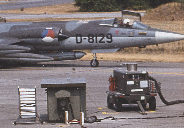
I watched the starting of operational RNLAF F-104s from close-by on two occasions, and the noise of the little jet starter cart was very impressive. I think the type was only used by the RNLAF. As far as I know, it was built by Fabrique Nationale (FN) and used a Boeing 502 jet engine. They were probably called 'turbo starter' in the RNLAF. I always wanted to scratch-build one, but I never found enough information, and it seems not a single one was preserved. But in 2020 I found many more photos, and I started building one, using 21st century scratch-building methods.


2D and 3D CAD

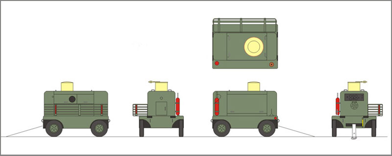
Two old issues of the IPMS-NL magazine MIP from 1978 contained a simple drawing with a few dimensions, but it was not sufficient for a model. Recently I discovered the NIMH Beeldbank, and found 700+ RNLAF F-104 photos. A small subset of these photos showed the jet starter, enough to make a 2D drawing. It is shown here in unfinished form, with a rough coloring.
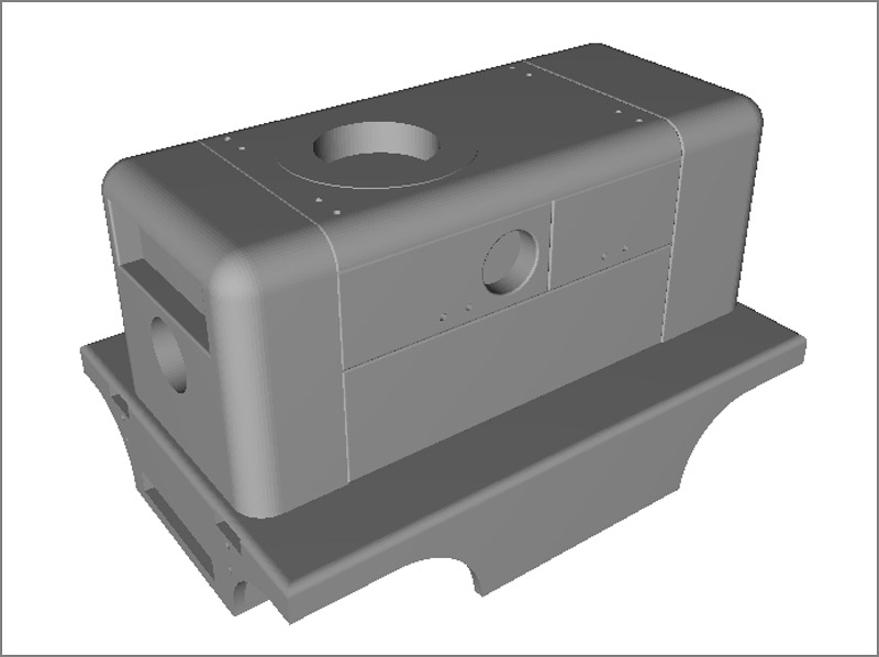
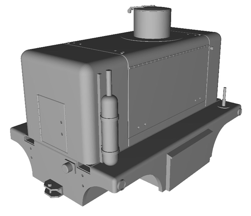
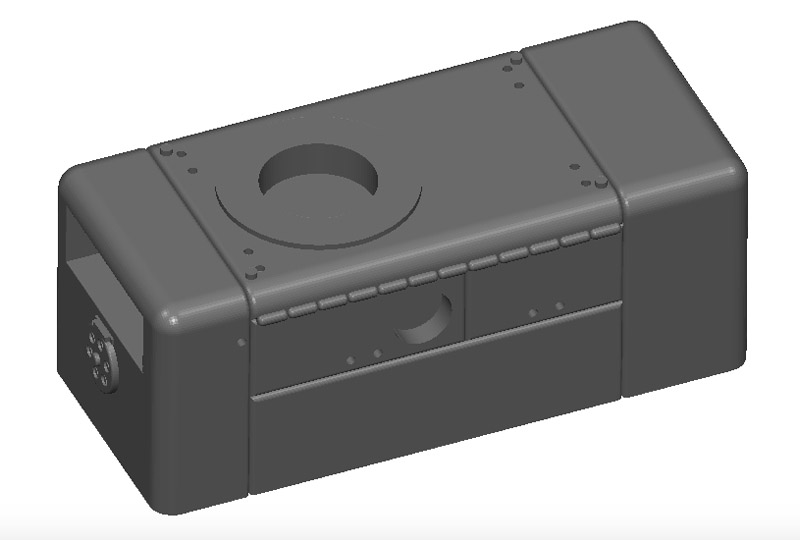
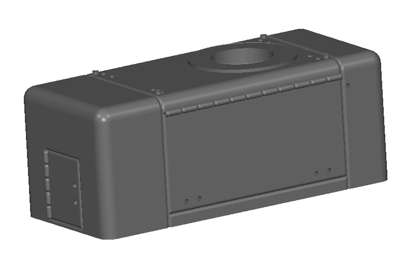
Next I converted the 2D drawing to a 3D model, so it could be 3D printed. Fortunately I still remembered how my old 3D CAD software worked. In one evening I did the top half, the next evening the bottom half. Both are preliminary designs, with many details missing. Shown here is an STL export, using this online STL viewer.
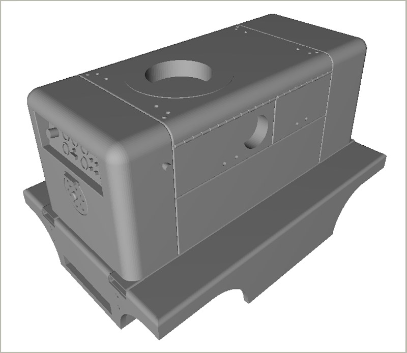
The third evening was spent detailing the model, with some twenty changes and improvements, including an instrument panel, piano hinges, a cooling air regulator, and beams for forklifting.
Work on the fourth evening was mostly spent on the rear side (towing hook, rear light), right side (fire extuingisher, parking brake, battery box, corner reflectors) and top side (exhaust with lid). On the front side I added a fuel gauge and improved the instrument panel. Left to do are the tow bar, and the wheels and tires.
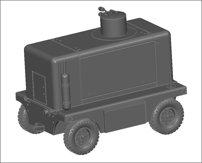
The wheels and tires were by far the biggest challenge for me. I did not have all measurements of the wheels (like the depth of the dish), so I had to design something rough and then tweek it visually. Interestingly, the wheels had two bolt patterns, the outer one serving to assemble the multi-part wheel (a.k.a. split rim) itself. Over to the tires, where the thread was the difficult bit. It became a compromise after crashing the old software too many times. Still, I think it will do for a small model like this.

For this and subsequent picture, I used another online STL viewer that did not have the extreme perspective of the previously used viewer. Actually it has no perspective, which takes some time to adapt to.
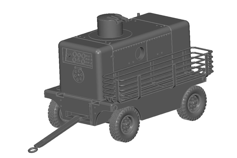
In the last round of work I added the wire basket and the towing bar. The wire basket is better made from metal wire than 3D printed, but I wanted to include it for a good evaluation of the 3D CAD model. Having it in 3D will also allow the development of a jig or a mold to help make the wire basket.
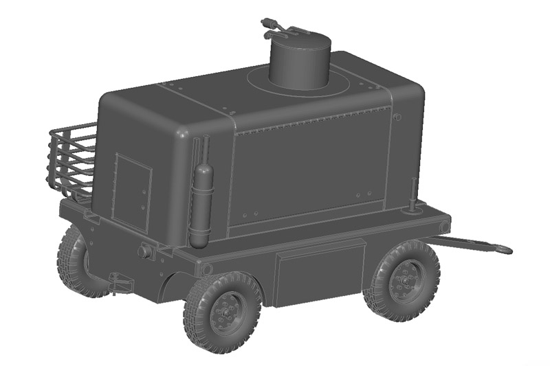
The finished model seen from the rear. It lacks all the handgrips and lifting hook by the way, that wil be made from wire.
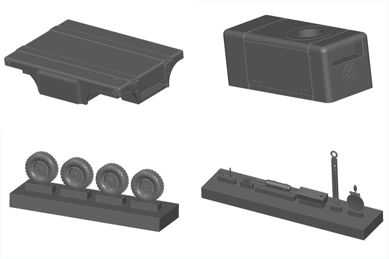
Here's how I broke up the starter cart in four parts / groups of parts for 3D printing. It's roughly based on how I would make a silicone rubber mould for resin casting. Let's see whether this works for 3D printing too. Still to be designed is a mould / jig to build the wire basket.

The large-diameter exhaust will be made of K&S Precision Metals 3/16" tubing with .014 wall thickness (4.8 mm x 0.4 mm). I can choose between #8104 aluminum, #8114 copper and #8129 brass. Maybe aluminum is the easiest to paint like the original, using transparent paints.

One detail that I forgot is to make the air hose couplings. My reference photos barely show them, so it will be difficult to recreate them. I have heard that the coupling that goes into the 104's wheel bay had a long handle, because the receptacle was deep inside the wheel well.


3D prints, attempt 1

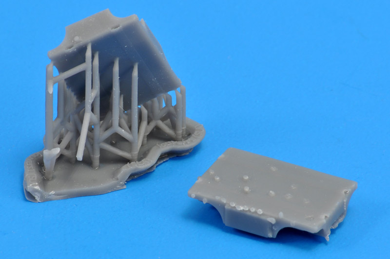
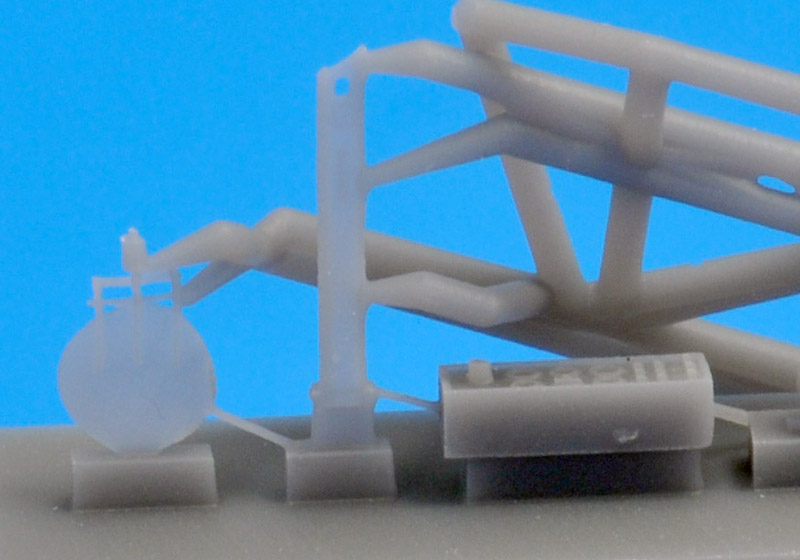
The first print attempt was not a 100% success. The attachment points of the supports required way too much clean-up, which in turn damaged the small details. Something else has to be tried here.
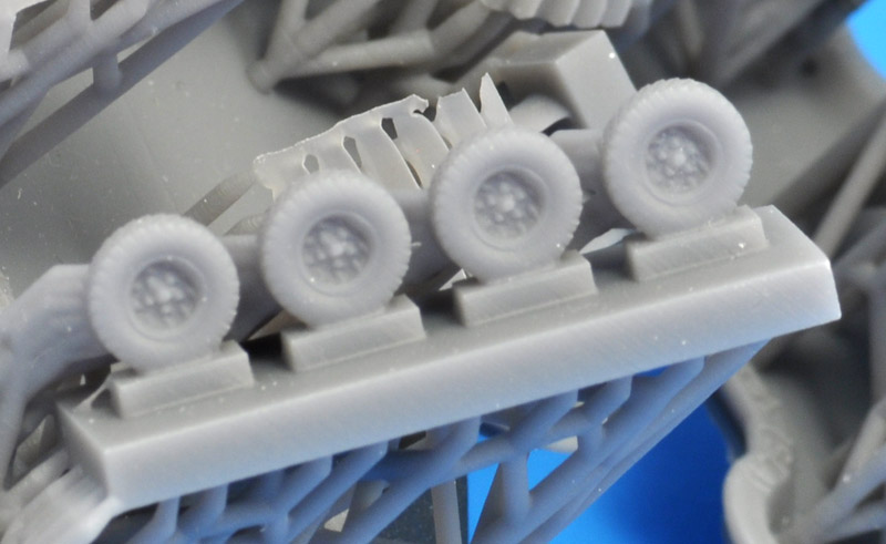
The following three photos show the results of the fifth print attempt. The wheels came out reasonably well I think. Once painted they should be good to go.
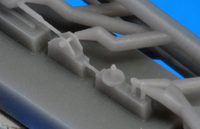
Roughly in the middle is the hitch. The pin is much thinner than my design, something to be investigated. The parts on the right (handbrake and remote control connectors) are not really useful.
From left to right: the lid for the huge exhaust came out pretty good, but I predict that it will have snapped in multiple pieces before I have removed it. Next is the towbar, that is 80% OK, but it's missing the towing ring at the top end. The instrument panel looks almost perfect.

I wasn't happy with the prints, and the problems took the wind out of the project. But it will be finished one day..


3D prints, attempt 2

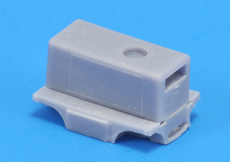
The second print attempt was much better, mostly because the supports were placed far better, leaving less damage to the sides that were important. There were many lessons to be learned from it, like that my scribed lines were far too small.
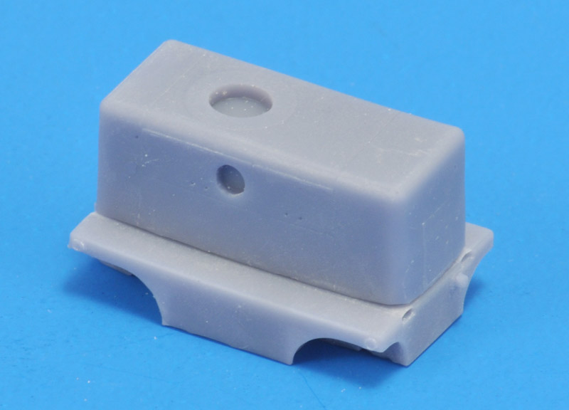
The same set of parts from the other side. Even the forklift openings in the lower part were printed perfectly.
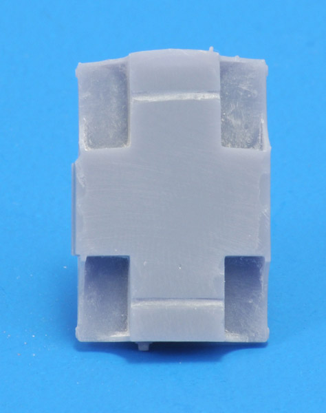
The parts still had some problems though. The upper part was not rectangular, the rear side (left) had tilted. There's also a slight curve to the lower side.
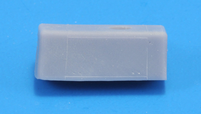
The lower part had a similar problem: the front part was bowed whereas it should be straight.


Redesign

The second print showed clearly that my details were far too small. Therefore all 'panel lines' were increased by giving all 'block' edges a 0.25 mm radius (previously 0.1 mm), all piano hinges were doubled in size, and all holes increased from 0.3 to 0.4 mm. The design looks a bit clunky now, but it probably works better in 1/72 scale.
The design looks a bit clunky now, but it probably works better in 1/72 scale. It demonstrated again that one problem of designing on the screen is that you're often surprised by the true size, either smaller of larger!


3D prints, attempt 3

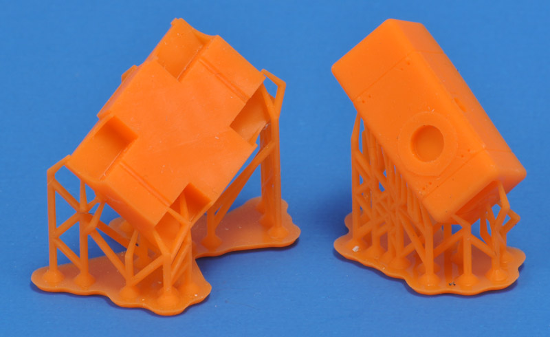
Club member Wim printed the next set of parts, printed in orange. They are very nice. But first I need to see how much damage is done by the supports.
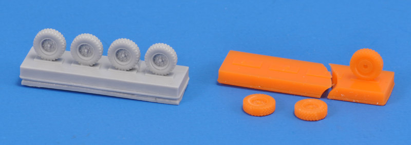
Here are the wheels. I was afraid that the 3D printed parts would be brittle, therefore I made a silicone mould right away. The print broke while removing it from the cured silicone rubber, so my assumption was correct. The cast parts are perfect, very happy with them. Diameter is slightly under 7 mm.
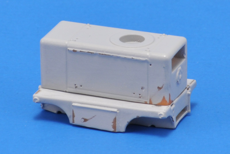
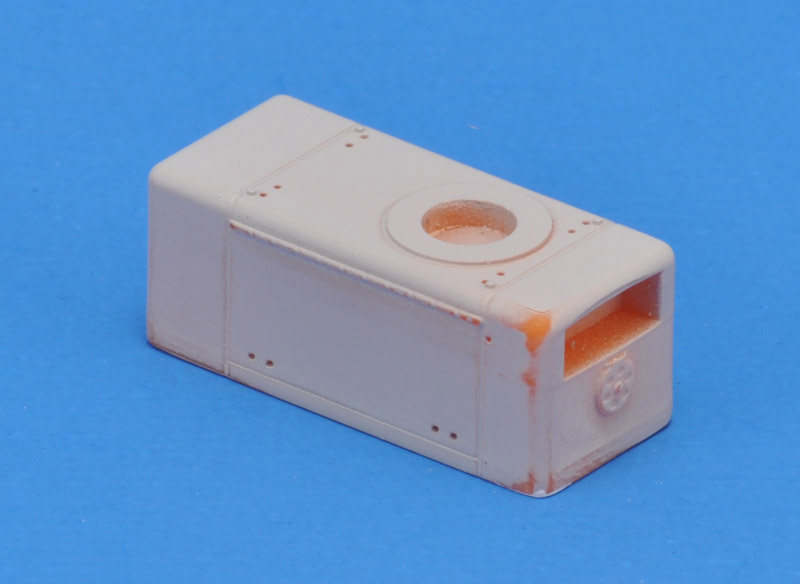
After four light coats of Tamiya Surface Primer, I sanded some areas that showed small printing defects.


Return to models page