3D printed parts for the Seminar 1/72 U-2C
| The Airfix, MPC, Academy and Seminar 1/72 U-2 have one thing in common: they have Q-bay hatches without any camera window details. I decided to try to design them in 3D CAD and have them printed. |
| The Airfix, MPC, Academy and Seminar 1/72 U-2 have one thing in common: they have Q-bay hatches without any camera window details. I decided to try to design them in 3D CAD and have them printed. |
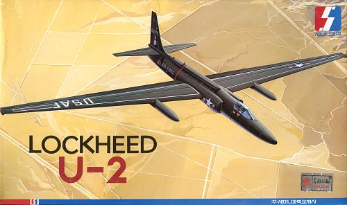
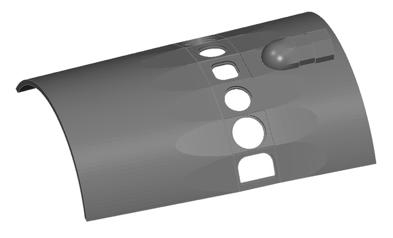
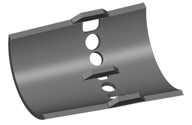
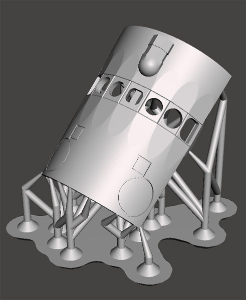
| Making a 3D CAD model of the B-camera Q-bay hatch is a bit of a challenge with the old and limited software that I know how to use. The picture shows the STL export of the first design step, generated using this online STL viewer. It lacks the scalloped flat areas ahead and aft of the seven windows, and the tracker camera fairing at the rear. The real hatch also has flush-fitting circular and square antennas, whose lines I would like to represent.
Maybe it's better to make a negative of the above, and use that for vacuum forming. That give integral windows, instead of seven tiny windows to install separately. Maybe something for later. | 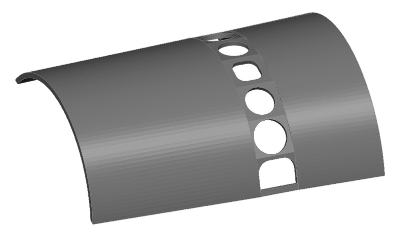
|
| One problem visible in the previous picture is the facetting of the curved panels. My old software could do no better unfortunately. A fellow modeler (thanks Martin!) tried it in a much later version, and this yielded a much finer detailed model. I now understand the 'surface deviation' and 'normal deviation' parameters better too, which will be useful for future projects.
Later I did some more experiments with the STL settings. I set the 'surface deviation' to 1/3rd of the print layer thickess; that seemed sufficient to me. To my surprise I got a really coarse-looking STL model, with way fewer facets than before. It turns out that the small size of the part allows a coarse STL model without compromising on the accuracy of the printed part. Another lesson learned, and you will see 'coarser' models after this point. Another observation is that the kit's Q-bay hatch has a rather different shape than the real one. The kit's hatch increases in height towards the rear, whereas the real one is the opposite. I decided to leave that problem. |
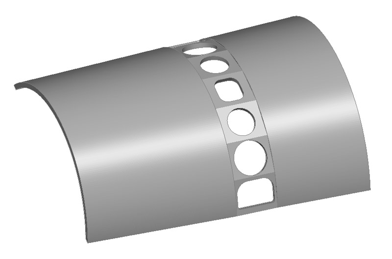
| Initially I had no idea how to make the flat scallops in the curved front and aft parts of the hatch. But thanks to a suggestion by fellow modeler and 3D CAD professional Martin I managed it. It took me several hours though! Due to the taper of the hatch as a whole, the flat scallops are bit different on the front and rear of the camera windows. But my 1/72 hatch design is already a lot better than the Cutting Edge B-camera hatch in 1/48 scale :-) | 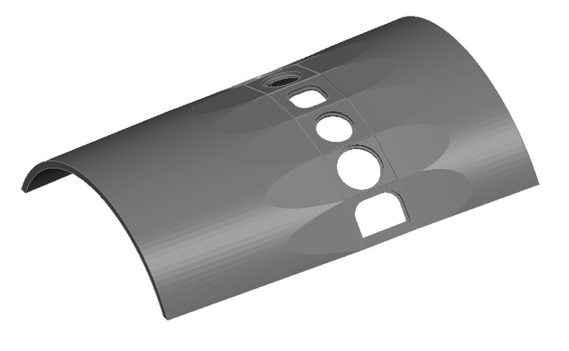
|
| The next detail to add was tracker camera fairing at the rear of the hatch. I had measured it from photos, and initially thought I had made it considerably too large. But a second photo measurement gave me the same numbers. Maybe it was the Cutting Edge part, with a tiny fairing, created the confusion. The shape of the front of the tracker camera fairing is not 100% correct, but I could not find a way yet to do it better. |
| Here's the result of the first prints of my part - really bad.. Maybe my design was too thin to print, at 0.4 mm thickness. The print company is busy trying to improve the results. | 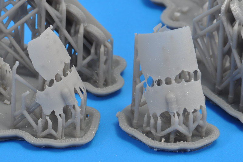
|
| On the fifth print attempt, the part came out about right. But its was very thin (0.35 mm, I had designed it as 0.40 mm) and I hadn't realised how weak the window area would be - it's a perfect 'perforation' of the part. The part had some 30 supports attached to it, and about halfway cutting through them, the part had already snapped in two. I roughly 'repaired' it with two braces made of 1x1 mm plastic strip, so I could test-fit it on the model. The fit wasn't 100% convincing. And the facets around the camera windows, although present, were hard to see. Back to the drawing board.. |
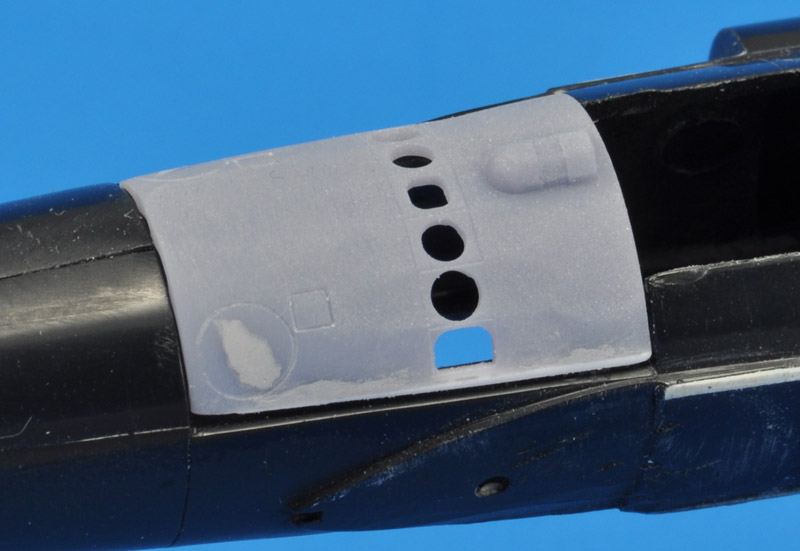
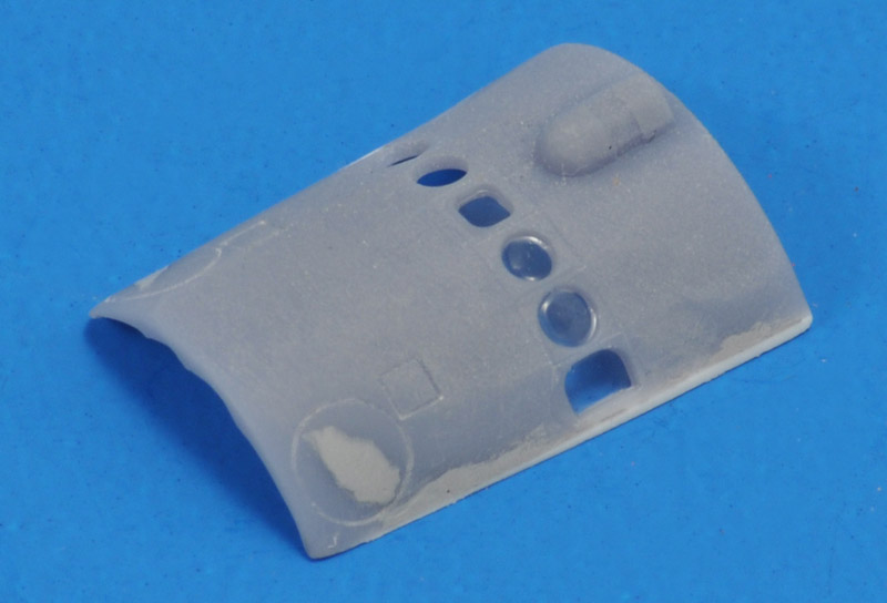
| One of the lessons learned was to increase the thickness; I doubled it from 0.4 to 0.8 mm. The window sills were removed (they were invisible on the print) and the panel lines around the windows were deepened.
Lastly I also learned how to 'engrave' panel lines in my old software, and hence the hatch now has two circular and two square antenna outlines. However I had to trick the software a bit, which leaves a ridge at the front end. But it is so thin that it will not be printed. | 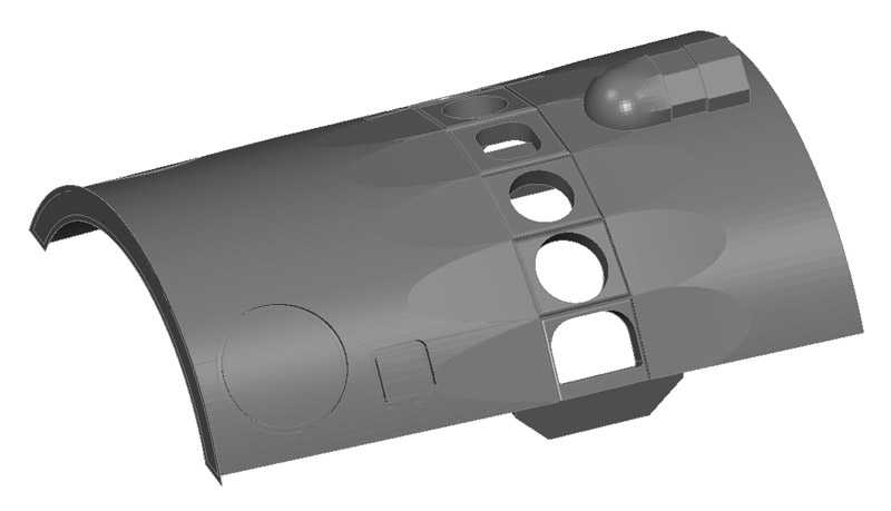
|
| And to reinforce the 'perforation' I added three braces, that are to be removed before use. I hope the strengthening is sufficient - the printing material is very brittle. |
| The second print attempt, the first that looked good! Both front corners were deformed slightly, they were set at an angle, a bit like 'dog ears' on the page of a book. I had to sand those areas, but that destroyed the scribed circular antennas on both sides. I tried to recreate them, and I found out that the 3D printing resin does not scribe well. | 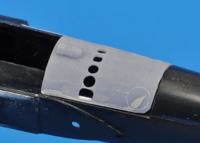
|
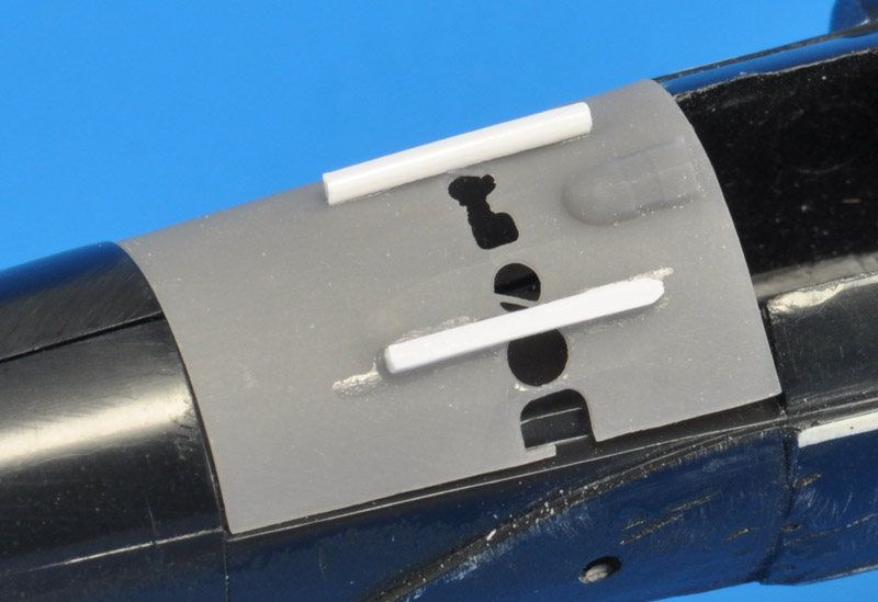
| The length was near-perfect (22.7 instead of 22.8 mm as designed), but the width was too small (16.0 instead of 17.0 as designed) - very strange! I extended the hatch with strips of plastic |
| I tried to photograph the 'dog ears', but it was near impossible. You can only see a vague shadow on the inside, at the top of the photo. | 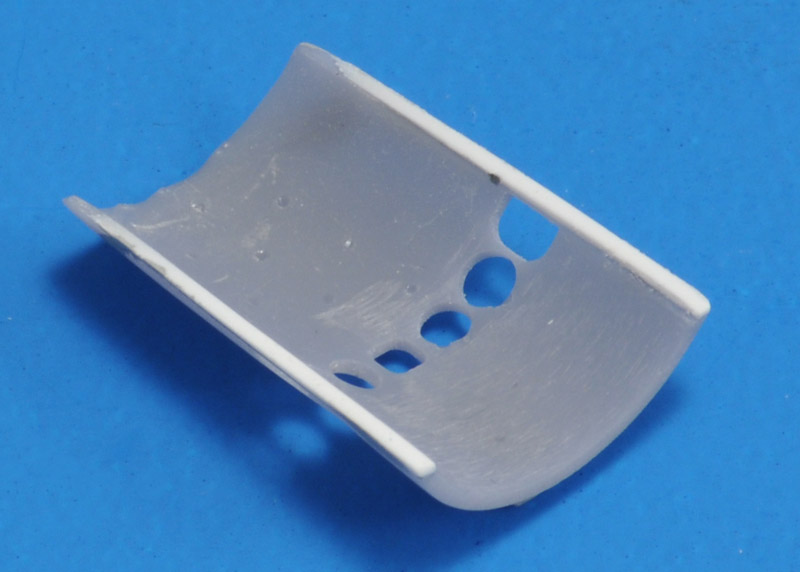
|
| Here's a test with Kristal Klear to make the camera windows. I did not expect much, but the result wasn't bad at all. |
| The third outsourced print attempt finally gave me a perfect result. It fits well, no repairs are requied, and there are almost no steps to get rid off. Very nice!
Unfortunately, after casting this part a few times, I saw a defect that spoiled the part slightly. You can see it as a 'dog ear' in the lower right corner. It took me some time to figure it out, but it was simply a lack of supports in that corner of the part. | 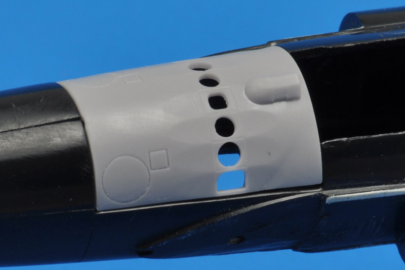
|
| That discovery made me realize that I needed to have full control over the supports. I learned how to use PrusaSlicer, and here's my first pre-supported part. I oriented the part such that no supports spoil the exterior side of the Q-bay hatch. |
| I'm not really sure that the upper edges of the camera windows need supports, but I added them anyway. They are placed such that the don't spoil the window coamings. | 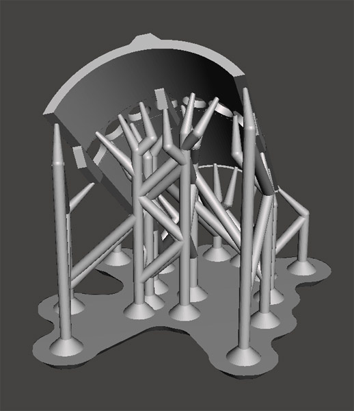
|
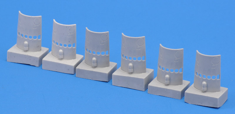
| Finally I had a 100% perfect B-camera Q-bay hatch. It took from 2020 to 2024, with large breaks, before this tiny part was done..
The B-camera Q-bay hatch is now in production, and shown here are the first six castings. See the For sale or trade & wanted page for more information. |