Pander S4 Postjager wing profiles
| Around 2010 Execuform issued a 1/72 scale vacform model of the Postjager. A 1/72 resin model is expected before the end of 2012. I initially planned to build the Execuform vacform, and started researching the subject. For some time, the black and white photos confused me thoroughly. But patterns emerged slowly, and it is now possible to analyze the colors with just five photos. The result was slightly surprising.
|
Wing profiles
There is not much data available on the technical design of the Postjager. One of the questions is the wing design, more specifically the wing profiles. The NVM drawings state that the center section was 'M12 17%' and the tip 'M12 11%', and it contains a table of profile ordinates (coordinates) for both. The use of the M12 profile is confirmed by one of the old newspaper articles listed at the end of the Postjager colors and markings page. But I found the use of M12 in two different thicknesses strange and confusing - I had never heard of a drastic rescaling of a profile. To answer that question, I looked into the design of the M12 profile. Normally, the ordinates of a profile are all you need. But in this case, to understand the 'thickened' version', the camber line and thickness distribution must be known, and preferably their mathematical equations known. A long search followed..
RLS Rapport A.436: 'Metingen aan een model van den vleugel van het S.4-vliegtuig voor de firma H. Pander en Zonen'
In the Dutch 'National Archief' in Den Haag I found an RLS report about wind tunnel measurements on a 1/20 scale wing, dated 4 April 1933. The measurements focused on the aileron and flap effectiveness, but luckily it also included a detailed measurement of the windtunnel model itself. No drawing or photo of the wing model were included. The report lists a centerline chord 175 mm, span 819 mm, area 0.1157 m2. X and Y are expressed as percentage of the centerline chord, Z is expressed as percentage of the span. Therefore, the measurements correspond to profiles 2.572 m from the centerline which is very close to the wing kink, and 7.387 m from the centerline which corresponds to the outboard edge of the flap. The measurements are copied below.
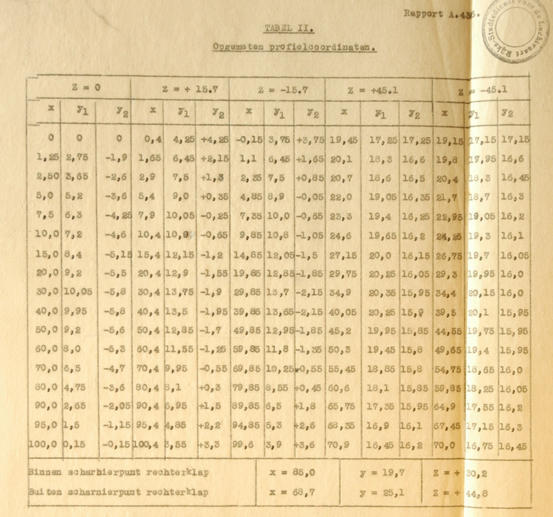
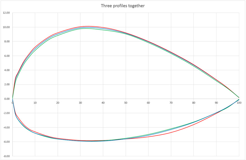
The first three profile measurements should be identical. After correcting for small incidence angle differences, and the y-position difference due to the model's dihedral, the three measurements agreed pretty well.
The average profile was calculated (blue), and it showed a thickness of 15.8%. Next, I added a 15.8% scaled M12 profile (red), see the analysis further down the page. The agreement is excellent, I think.
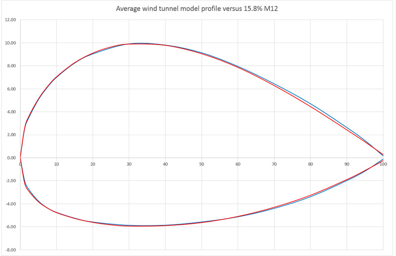
Therefore, I conclude the wind tunnel model had a 15.8% M12 profile for the area between the outboard engines. Since construction of the real aircraft started soon after, I would guess the designer retained this profile choice.
Comparison with NVM drawing
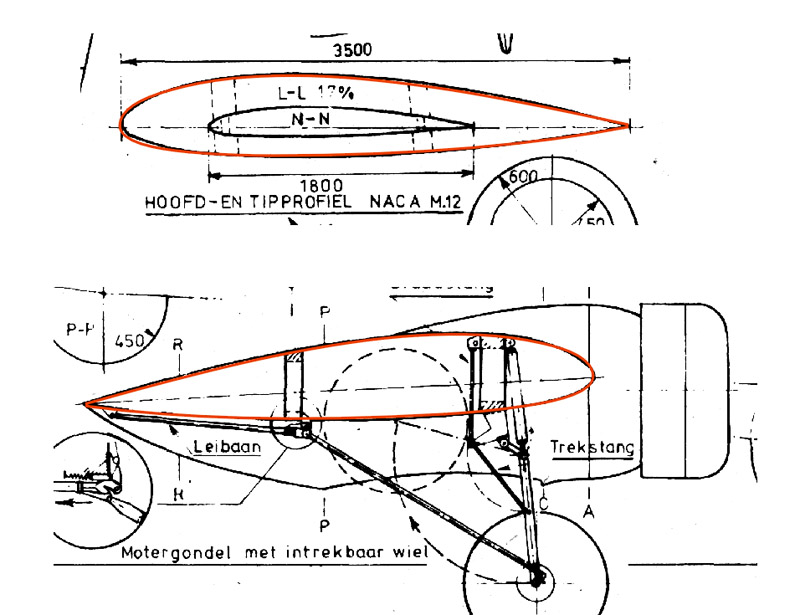
I copied the 15.8% M12 over the profiles shown in the NVM drawing. Since the drawing states that the profile is 17% thick, I was surprised the match was quite good.
Comparison with Pander preliminary drawing
I copied the 15.8% M12 over the preliminary drawing that I found in the 'Nationaal Archief', and again the match was good.

Munk M12 profile
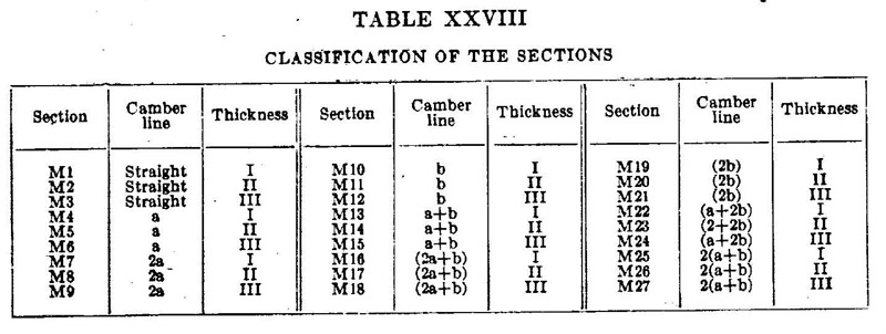
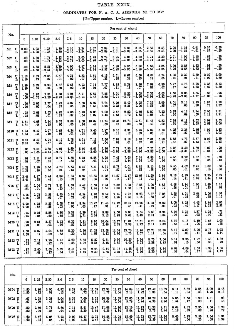
The 'M12' profile is the 12th Munk-designed profile, in a series of 27, for NACA. Their profile data and performance are all listed in NACA Report 221: Model tests with a systematic series of 27 wing sections at full Reynolds number. Table XXVIII of that report lists which combinations of camber lines and thickness distributions were used. Table XXIX list the ordinates of all 27 profiles. It includes an obvious typing error for the 80% chord lower side ordinate. Furthermore, I found that M12 has a Göttingen equivalent, the Go 676 profile, but I could not find out which came first.
Munk's camber lines
Unfortunately, NACA Report 221 does not contain the mathematical models for the three camber lines and the three thickness distributions, it only identifies them as "straight, a and b" and "I, II and III" respectively. Therefore, I entered the data of six profiles in Excel, and starting doing various analyses to try to understand the way these profiles were constructed.
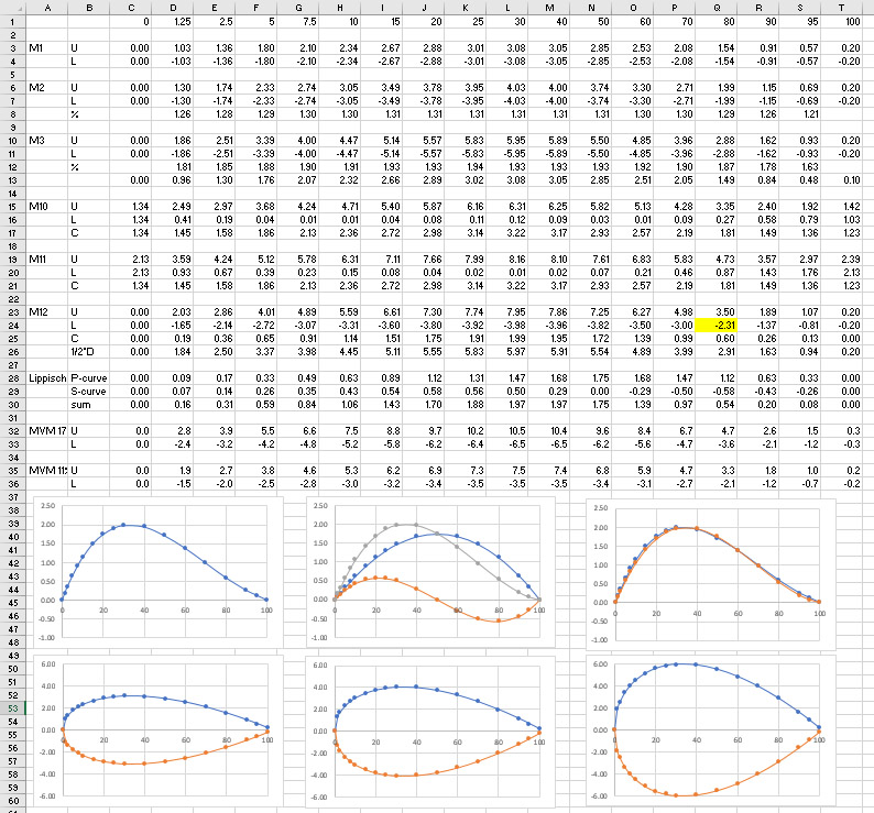
The good news is that I was able to establish the camber line equation of M12 reasonably well. Note that M10 and M11, with the same 'b' camber line, don't have their start and end point on the chord line - welcome to the world of old profiles. Seeing the slight reflex at the rear, and knowing the German background of Munk, I remembered the camber line equations that we once studied during the reconstruction of the Me-163B wing profile, using a P-curve and an S-curve combination for the camber line ('Skeletlinie'), see Göttingen 765: attempt 6: camber line plot.
And indeed, the combination of n = 1 and h = 1.75 for the P-curve and m = 1 and lambda = 1.5 gave a fairly close approximation of the camber line calculated from the profile data.
Munk's thickness distributions
I think that the thickness distributions I, II and III are identical except for their thickness, but I have not yet identified a model that describes them. It's not the NACA 4 distribution, I checked that. Considering Munk's German background, it's most likely one developed in Göttingen. Also, the information on the leading edge radius is also missing.
Luckily, I got expert help from Keith Pickering, who provided the excellent report 'Recovered equations and ordinates of the Göttingen 765 airfoil' for my
Me 163B Komet website. He used the same method here, optimised the results with a least-squares method, and his analysis resulted in the following model for the thickness distribution.
The thickness distribution ahead of the maximum thickness point x = m is described by:
± yt = T /.2 * (a0 * x0.5 + a1 * x + a22 * x2 + a3 * x3)
m = 0.323075441, so the maximum thickness is a bit aft of the reported 30% chord
T = 0.119434915
a0 = 0.296308751
a1 = -0.185708798
a2 = -0.01012475
a3 = -0.218443619
The thickness distribution aft of the maximum thickness point x = m is described by:
Göttingen 676
I tried to find more information on the Gõttingen 676, which is the M12 equivalent, although I still don't know which came first. I consulted 'Aerodynamische Profile - Windkanal-Messergebnisse, theoretische Unterlagen' by Friedrich Wilhelm Riegels from 1958. On page 150, the ordinates are listed, and they do not agree with the numbers in NACA Report 221. On page 128 it lists performance data of 676, and quotes 'E IV' as the source. Unfortunately, no list of references is provided, so the trace ended there.
In 2020 I learned that 'E IV' is very likely 'Ergebnisse der Aerodynamischen Versuchsanstalt zu Göttingen - IV. Lieferung' (online version).
Parametric model
Worth mentioning is Parametric airfoil catalog Part II Goettingen 673 to YS930 by Thomas Melin. Melin presents a method to represent airfoils by four Bezier curves, including the Go 676 (equivalent to M12) profile. It might be useful for a 3D model.
Munk M12 conclusions
From NACA Report 221 I conclude that Munk himself combined various thickness distributions with a camber line. Since thickness distributions I, II and III appear identical in shape, you could also say that he scaled the thickness as desired. In that sense, a '15.8% M12' profile would fit in Munk's approach. But the drawback is that no aerodynamic characteristics are known for a self-defined thickness. It would seem more logical to me to use profile M15 then, that was an 18% profile using the same camber line, and for which all aerodynamic characteristics were measured and report in NACA Report 221. Therefore, I still don't think I understand the reasoning for the '15.8% M12'.
Later I found one more example of 'creative engineering' with profiles. The Gee Bee R1 and R2 from 1932 had a modified M6 profile, selected for the near zero pitching moment coefficient, so the horizontal tail surfaces could be made small(er). One source says it's a 65% thickness M6.
2020 update: Munk's Aero Digest articles
In 2020, I found very valuable information on the Munk profiles. I always wondered how designer Slot came across the Munk profiles and decided to employ them with his own modifications. Possibly the various NACA reports were available at the RLS. In March 2020 I may have found the 'inspiration' for the use of M12 for the Postjager. Munk published a series of 18 articles in 'Aero Digest' in 1930 and 1931. These volumes can be downloaded as PDFs on the Internet Archive site.
| 1
| The creation of air forces
| July 1930
| pages 583, 718, 720, 722 of the PDF
|
| 2
| Aerodynamic language
| August 1930
| pages 808, 908, 910 and 912 of the PDF
|
| 3
| Pressure
| September 1930
| pages 46, 190, 192 and 194 of the PDF
|
| 4
| The square law
| October 1930
| pages 275, 364, 366, 368 and 370 of the PDF
|
| 5
| Friction
| November 1930
| pages 458, 550 and 552 of the PDF
|
| 6
| The resolution of wing air flow
| December 1930
| pages 626, 716, 718 and 720 of the PDF
|
| 7
| The creation of lift by a wing section
| January 1931
| pages 56, 142, 144, 146 and 148 of the PDF
|
| 8
| The center of pressure
| February 1931
| pages 224-225 and 292 of the PDF
|
| 9
| Mathematical wing sections
| March 1931
| pages 385, 456 and 458 of the PDF
|
| 10
| The "M" wing sections
| April 1931
| pages 554-555 of the PDF
|
| 11
| The induced drag
| May 1931
| pages 818-819 and 888 of the PDF
|
| 12
| The composite wing air flow
| June 1931
| pages 976-977 and 1003 of the PDF
|
| 13
| The aspect ratio
| July 1931
| pages 49 and 131-132 of the PDF
|
| 14
| Plotting wing characteristics
| August 1931
| pages 197, 206 and 208 of the PDF
|
| 15
| The choice of a wing section
| September 1931
| pages 331, 400, 402 and 404 of the PDF
|
| 16
| The measured lift of airfoils
| October 1931
| pages 470-471 and 538-539 of the PDF
|
| 17
| The distribution of lift
| November 1931
| pages 596 and 661-664 of the PDF
|
| 18
| Means for increasing the lift
| December 1931
| pages 719 and 777-778 of the PDF
|
|
The article titled 'The "M" wing sections' in the April 1931 issue contained the information that I was looking for. It contains descriptions of the P-curve (P for parabola), S-curve (S because of the shape) and T-curve (T for thickness), from which his M-series profiles are constructed, and equations for these three curves. Initially I believed the equations presented in the article were all wrong, until I noted further down the article text that Munk defined the leading edge as x = 1 and the trailing edge as x = -1. I derived 'new' equations for the now commonly used definition of the leading edge as x = 0 and the trailing edge as x = 1.
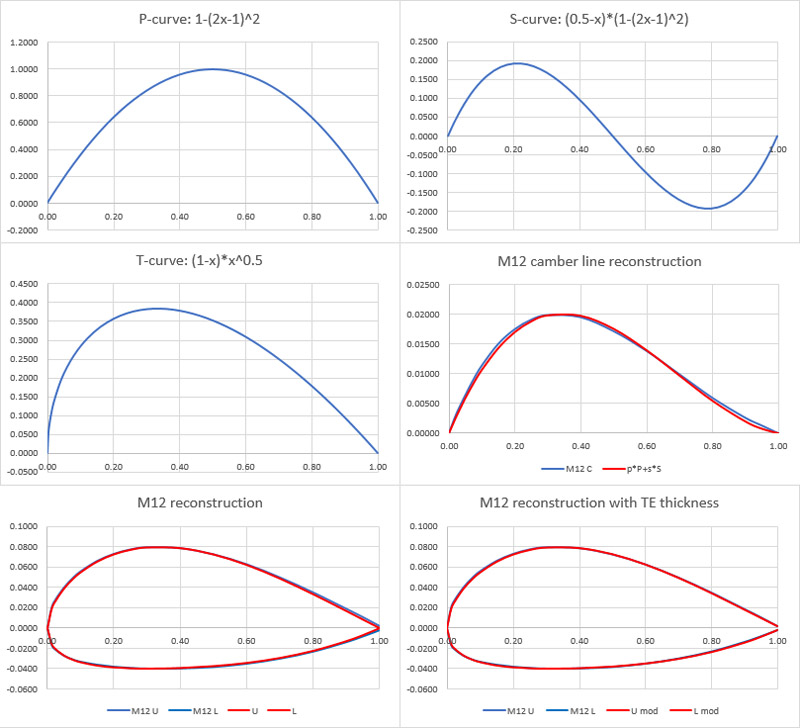
P-curve: 1-(2x-1)^2 or: -4x^2+4x max at x=1/2, y=1
S-curve: (0.5-x)*[1-(2x-1)^2] or: 4x^3-6x^2+2x max at x=0.2113, y=0.1925
T-curve: (1-x)*x^0.5 or: x^0.5-x^1.5 max at x=1/3, y=0.3849, min at x=0.7886, y=-0.3849
The profile is then constructed by adding up the curves with suitable scaling factors (p, s and t):
upper: p*P + s*S + t*T
lower: p*P + s*S - t*T
I tried to reconstruct the M12 profile from NACA Report 221. Work starts with the camber line (fourth graph), and I could only achieve a moderately accurate fit (in red), using the following parameters:
The next step is adding the thickness distribution, using the following parameter. M12 coordinate data from NACA Report 221 in blue, reconstruction in red in the fifth graph. Please note that I did not use equal scales for the axes, so the profile is not represented realistically.
One noticeable difference is that the M12 profile data shows a finite thickness trailing edge of 0.4%, and the T-curve does not allow for that.
Actually, the thickness curve can be modified in a way that a finite thickness at the trailing edge results. For example (1-x+a)*x^0.5 with a=0.013 gives a 0.4% thick trailing edge to the M12 profile, just like the official coordinates show. Parameter 't' is reduced from 0.155 to 0.1525. This reconstruction is shown in the sixth graph, and the fit is 98%.
p=0.0175
s=0.0300
t=0.1525
a=0.013
| 
|
|
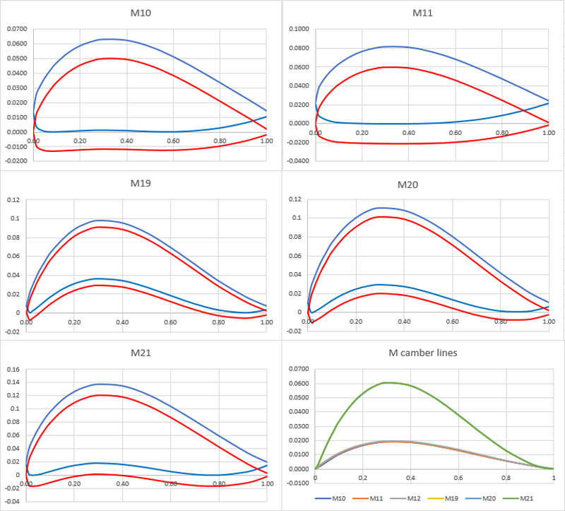
One way to improve the camber line fit is to calculate all camber lines from the M-series that use the same Munk 'b' type camber line (M10, M11, M12, M19, M20, M21); see the first table scanned from the NACA report. This should give a better average than just using the single (calculated) M12 camber line.
Note: the fourth data point for the lower surface of M21 appears to be in error: 0.083 fits a lot better than 0.83.
All profiles except M12 have a chord line that is 'raised' and tilted, so the profile 'rests' on the horizontal axis. Therefore, I shifted and then rotated the original profile data (in blue), so they conformed to current standards (in red). A drawback is that this all adds to the uncertainty of whether this is what Munk himself did back in the early twenties.
Next, the camber lines were calculated and gathered in the sixth graph. This shows an interesting error in the first scanned table from NACA Report 221: the camber lines of M19, M21 and M21 are not '2b' but '3b'.
|
|
All camber lines were gathered in one graph, with those of M19-M21 scaled down by a factor of 3. This immediately showed that the exercise was not very successful: there is considerable spread. Nevertheless, the average was calculated (blue), and a 'best-fit' p*P+s*S curve was sought (red).
| 
|
I think the possibilities for analysis end here. New original data is probably required to get any further. 'Fluid-Dynamic Lift' by Hoerner, pages 2-1 to 2-4, lists a number of references that look useful. The text was OCR'd and copied below, but beware of errors. I checked a few references so far, but found nothing on Munk's P-, S and T-curves yet.
Reference
| My notes
|
| (1) Practical information on foil sections and their mechanics can be found in engineering books, such as:
|
|
| a) Diehl, "Engineering Aerodynamics", Ronald 1936.
|
|
| b) Prandtl, "Führer Stromungslehre", 1942; "Essentials of Fluid Dynamics", London & New York 1952.
|
|
| c) Goldstein, "Developments in Fluid Dynamics", 1938.
|
|
| d) Schlichting,"Boundary Layer Theory", McGraw-Hill.
|
|
| e) Wood, "Aircraft Design". Author Uni Colorado, 1963.
|
|
| f) Pope. "Wing and Airfoil Theory", McGraw-Hill.
|
|
| (2) Early investigations of wing sections:
|
|
| a) Lilienthal, "Vogelflug/Fliegekunst", Berlin 1889.
|
|
| b) Eiffel, "La Resistance de l'Air et l'Aviation", and "Nouvelles Recherches ..." Paris 1910, 1919.
|
|
| c) Munk (& others), Systematic Tests, Tech Berichte der Fliegertruppen Vol I (1917) and Vol II (1918).
| Full title is' Technische Berichte : TB / herausgegeben von der Flugzeugmeisterei der Inspektion der Fliegertruppen Charlottenburg. vol.1 (1917)' (link showing cover page).
|
| (3) McLarren. "Wright Flyer", Aero Digest July 1953.
|
|
| (4) Theory and tunnel testing of Joukowsky sections:
|
|
| a) Joukowsky, Zeitschr Flugtech Motorluft 1910, p 281; also in his "Aerodynamique", Paris 1916
|
|
| b) AVA Gottingen. 36 Foils. Erg III and IV (1927/32).
| Full titles are 'Ergebnisse der Aerodynamischen Versuchsanstalt zu Göttingen - III. Lieferung', see online version and 'Ergebnisse der Aerodynamischen Versuchsanstalt zu Göttingen - IV. Lieferung', see online version. The latter has Go 676 (M12 equivalent) information on PDF page numbers 31 and 80.
|
| c) Glauert. Generalized Family. ARC RM 911 (1924)
| Full title: 'ARC/R&M-911: A Generalised Type of Joukowski Aerofoil' (online version)
|
| d) ARC, Series Tested. RM 1241 (1929) & 1870 (1939).
| Full title: 'ARC R&M-1241: Experiments on a series of symmetrical Joukowski sections', by Page, Falkner, Walker (online index)
|
| (5) British information on airfoil sections:
|
|
| a) Pankhurst, NPL Catalogue, ARC C'Paper 81 (1952).
|
|
| b) Experimental results are found in (36).
|
|
| c) Nonweiler, Survey. Aircraft Engg 1956 (July).
|
|
| (6) Riegels, "Aerodynamische Profile", Munchen 1958; Theory & Experimental Results Over Past 30 Years. Also "Aerofoil Sections", Butterworth (1961).
|
|
| (7) A variety of wing sections can be found in:
|
|
| a) Ergebnisse AVA Gottingen, 4 volumes (1920/32).
| See 4b for more details
|
| b) Louden, Collection of Foils, NACA TR 331 (1929).
|
|
| c) ARC;RAF-34, RM 1071, 1146. 1087, 1635, 1708. 1771.
|
|
| d) Characteristics of airfoil sections from all over the earth, at lower R'nurnbers collected in NACA T Rpts 93. 124, 182, 244, 286, 315 (1920 to 1929).
|
|
| (8) Reflexed foil sections for airplane wings:
|
|
| a) Defore, In V'Density Tunnel, NACA TN 388 (1931).
|
|
| b) Jacobs, "M" Series Foils, NACA Rpt 532 & 628.
| NACA Report 532 is titled 'The Soap Bubble method of Studying the Combustion of Mixtures of CO and O2'. Maybe NACA Report 352 'Large-scale aerodynamic characteristics of airfoils as tested in the variable density wind tunnel' was meant? It does not contain mathematical models for airfoils. NACA Report 628 is titled 'Aerodynamic characteristics of a large number of airfoils tested in the variable-density wind tunnel' and does not contain information on mathematical models for airfoils.
|
| c) 23012 (figure 5) considered to be reflexed ?
|
|
| d) 2-R-12 Sections in VD Tunnel, NACA TR 460.
|
|
| e) Moscow, 'B' Airfoils, CAHI Rpt 903 (1923).
|
|
| f) British RAF-34 (figure 3), ARC RM 1771 (1936).
|
|
| g) For supercritical M'Numbers, NACA T'Rpt 947.
|
|
| (9) Fage, Lift and Drag =f(A), ARC RM 903 (1923)
|
|
| (10) For example, a=4 (as in the 64 Series of NACA airfoil sections) means that at design lift, pressure due to camber remains at its minimum plateau up to x = 0.4c.
|
|
| (11) Flow pattern and mechanics of vortices:
|
|
| a) Betz, About Vortex Systems, NACA TM 767.
|
|
| b) Newman, Trailing Vortex, Aeron Quart 1959 p 149.
|
|
Other finds:
Report no. 460 The characteristics of 78 related airfoil sections from tests in the variable-density wind tunnel gives a good explanation of the early NACA profile geometry
Book: Applied Computational Aerodynamics - A Modern Engineering Approach. Appendix A: Geometry for Aerodynamicists (pages 731-765) (link).
NACA Report 331: Collection of Wind Tunnel Data on Commonly Used Wind Sections. It has slightly different M12 profile data, with a sharp trailing edge, and 3.62 instead of 3.60 coordinate.
M. Munk und E Hueckel, Systematische Messungen an Fluegelprofilen, Technische Berichten der Inspektion der Fliegertruppen Band 1, Seite 148
Weitere Untersuchungen von Flügelprofilen. T. B., Bd. I, S 204.
Weitere Göttinger Flügelprofiluntersucbungen. T. B , Bd. II, S. 407.
Munk, M. und Pohlhausen, A.: Messungen an einfachen Flügelprofilen
T. B., Bd; I, S. 164.
Return to models page


