A+V Models 1/72 AQM-91A Firefly
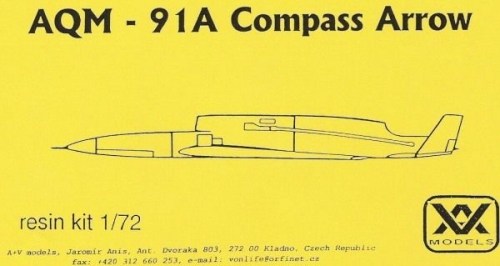
| I think it's quite amazing that a resin model exists of this obscure RPV. You will probably only know the Teledyne-Ryan Model 154 AQM-91A Firefly if you've read 'Fireflies and other UAV's'. The small batch that was built was (probably) scrapped before it became operational, in its task of unmanned reconnaissance over China. See Wikipedia for a summary of its history. My interest in this RPV grew slowly but steadily while researching the AQM-34 Firebee for my website on the subject. And when I came across the A+V Models kit at the IPMS-NL 2006 Nationals, I bought it for 17 euros.
|
Model quality
You get eight resin parts: two fuselage halves, two wings, and four tail surfaces. The castings are of good quality, without any pouring stubs to be cut off, which saves a lot of work. Air bubbles are absent, and the resin is nice to work with. The instructions consist of one page of 1/72 drawings and one page copied from 'Robot aircraft today - Jane's Pocket Book 13' from 1977. There are no painting instructions or decals. Although it isn't shown on the box or instructions, it appears that the catalog nummer is #89.
Model accuracy
Initially I thought the model was pretty accurate and a fairly quick build, but that changed when I started building the model. The model has a number of serious shape problems that require substantial changes. The main problems are:
the fuselage has a multitude of problems:
the nose is pointing up and the cross section isn't accurate, lacking the flat facets at the lower side
the inlet is much too small, and quite rough
the exhaust area lacks a 'pen-nib' fairing behind the exhaust opening
the wing roots are quite asymmetrical
the lower side of the rear fuselage is rounded where it should have sharp edges
the resin wings have a slightly curved 'sabre' shape, both the leading and trailing edges are slightly curved. Perhaps the silicone mold sagged during the casting of the resin parts? Possibly the root chord is too small, compared to photos
The most detailed drawing I could find came from 'World Unmanned Aircraft' by Kenneth Munson, but I largely relied on photos to get the shapes right. Five books yielded some 15 photos total. The shape modifications discussed below are bigger than anything I've done before, but they went rather easily and naturally. I think I learned a lot from my 1/72 AQM-34L project, especially the study of shapes, how to measure from photos, and how to translate it in plastic.
Fuselage reconstruction
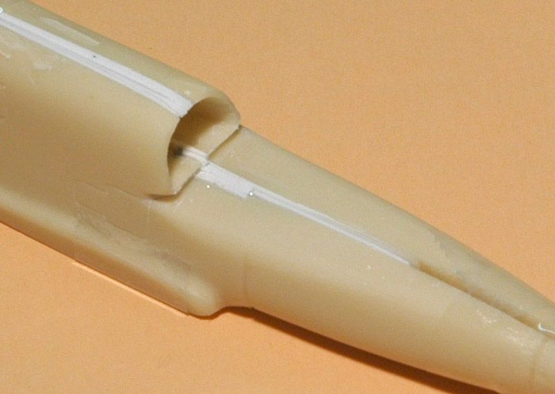
| After I opened the inlet with files, I concluded the inlet was way too small. The basic problem is that the forward fuselage is too high. Measuring from photos I concluded that 1.2 mm had to go. A lot of filing later, I had a much larger inlet opening. A secondary problem is the fuselage sides are canted too much. I shimmed the top joint with plastic card, 1mm on each fuselage half. Measurements also showed that the inlet face was placed some 2 to 3 mm too far forward. I moved it back 2 mm, and also cut a boundary layer bleed slot below the intake. It started to look like the photos.
| 
|
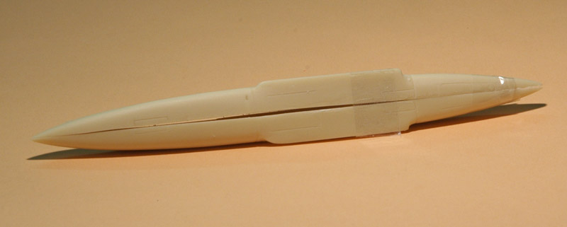
| Another fuselage problem: it becomes wider after the inlet, which results in a too fat rear fuselage. To make it 13 mm wide all the way, I removed 1 mm of resin at the wing's trailing edge from the lower joint, tapering to 0 mm at the leading edge and at the rear tip of the fuselage. The resulting fuselage needed quite some clamping to fit again. That wasn't acceptable, so I 'bent' the fuselage sides with sawcuts and shims. This technique is explained in detail for the rear fuselage modification.
|
| The nose section is another part of the model that is not very accurately shaped. Among other things, the radome sits too high. Together with the curved rear fuselage it gives the fuselage an awkward banana shape. Note that that about a millimeter of resin had been sanded away just ahead of the inlet, and this exaggerates the banana shape.
| 
|
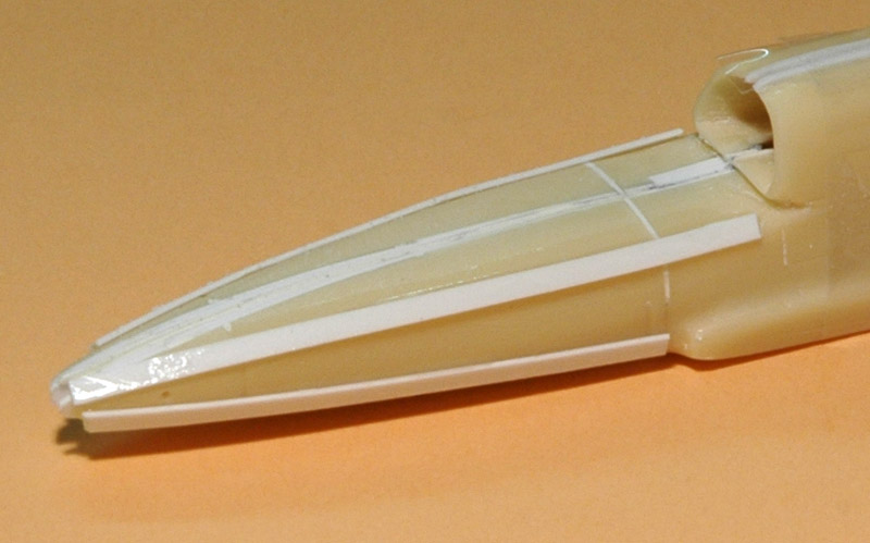
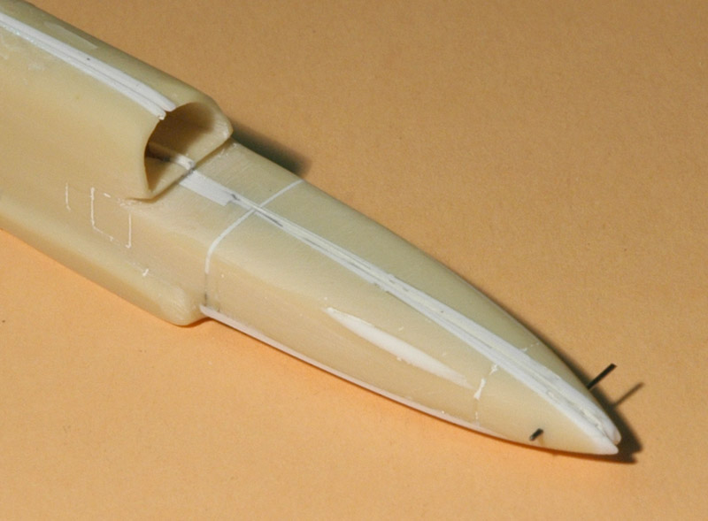
| First task was 'bending' the front fuselage downwards. I started with the left fuselage half, laying it down on the side view drawing to see what needed to be changed. I used a razor saw to make a cut just in front of the air intake, from the top side, leaving the lower fuselage intact, so it could serve as a hinge. The top side was then shimmed (visible as a white line) until the radome had moved down in accordance with the drawing . Due to other fuselage modifications, the forward fuselage parts no longer touched, they stood open. I compared it to photo and concluded that it needed a wider nose section anyway. Therefore I packed the gap with pieces of plastic card. You can see this gap tapering towards the inlet.
|
| The photo above shows that I glued strips of plastic card to the four corners of the nose sections, to make a more square cross section. These strips were subsequently sanded down, as seen here. The use of white plastic on a tan model is not ideal, because the color difference makes judging the shapes difficult. The model needs to be painted to solve that problem.
| 
|
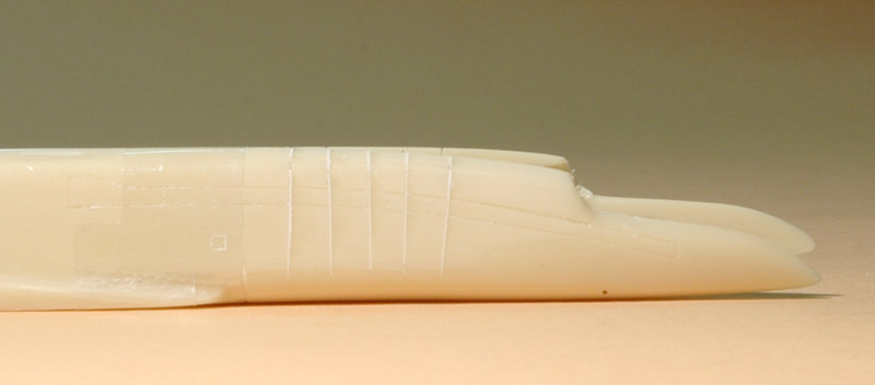
| The rear fuselage had several shape problems too. Up to the engine exhaust, the lower contour should be in line with the center and forward fuselage. The model has a curved lower contour, and at the engine exhaust it's already 1 mm above the correct contour. I bent it down by making five sawcuts from the top (long live the JLC razor saw), and shimming the sawcuts at the top with plastic card of a suitable oversized thickness. The remainder of the sawcut was then filled with thinner plastic card and superglue. The photo shows the original right fuselage side and the modified left fuselage side.
|
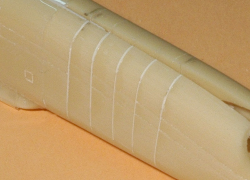
| A top view shows the sawcut and shimming technique in detail. The process does put some strain on the resin part, but it's much more controlable than bending the resin by heating. The right fuselage side got a similar treatment, but things didn't go as smoothly there. No less than eight sawcuts were required before the right amount of 'bend' was achieved. And by then the fuselage side was no longer straight in plan view: due to the shimming near the centerline, the tail was bent away from the centerline. It was easily solved by making four sawcuts in the sides and shimming these too.
| 
|
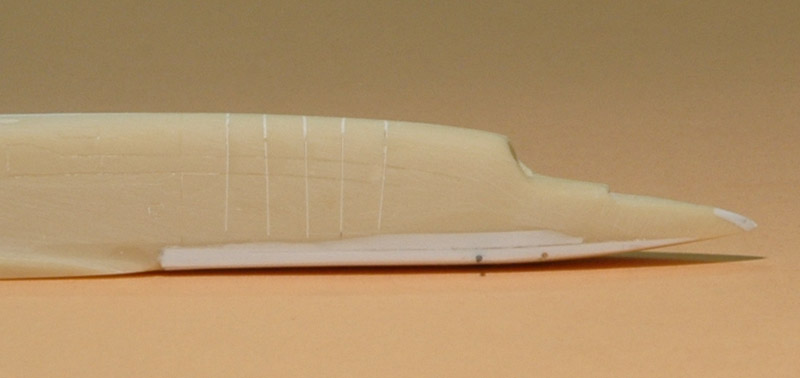
| Work continued on getting the rear fuselage shape right. Next were the lower edges, round on the model but sharp on the real thing. I glued several strips of plastic card on the corners (similar to the nose) and started sanding. The change made the rear fuselage look rather fat, but photos showed that this was correct. The rear end was reshaped considerably too, it now has a trapezium cross section and almost looks like a squarish radome.
|
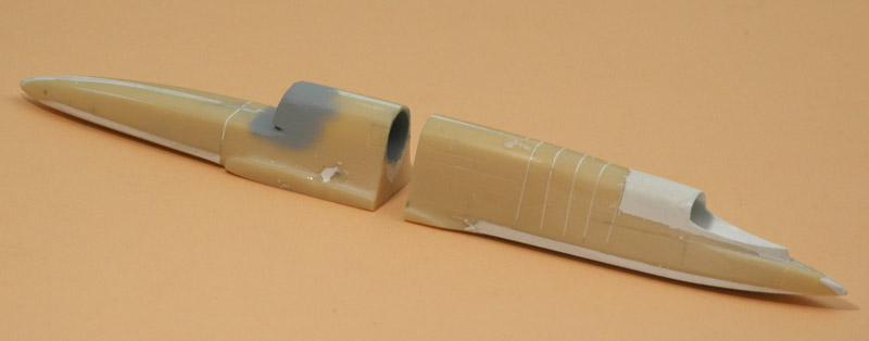
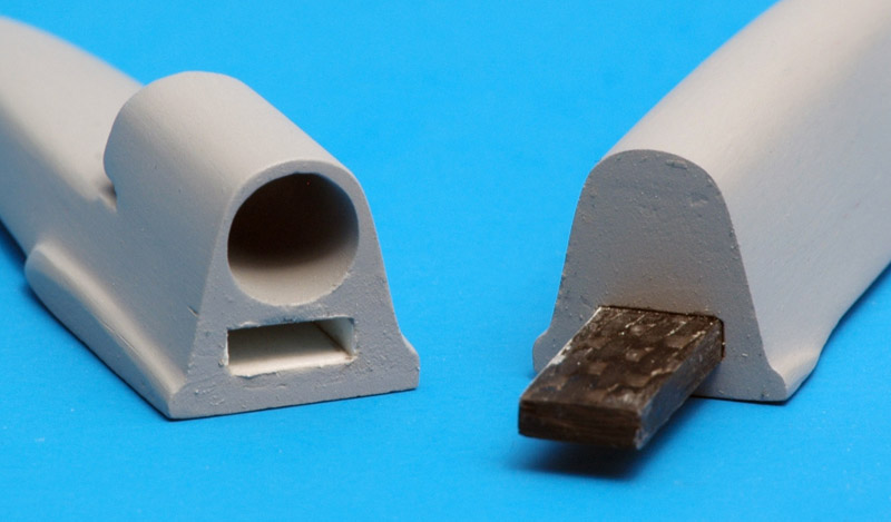
| Next problems to tackle were the inlet duct and the exhaust. This required a fairly drastic change: I decided to switch to forward and aft fuselage parts instead of left and right fuselage halves. I filled the hollow fuselage halves with Milliput because I wanted to work with solid parts. In the front fuselage I left a rough inlet duct open, and similarly a rough exhaust was left open. By overlaying a side view drawing with a rectangle having the basic J97 dimensions, I guestimated where the engine compressor would have been, and there I cut the fuselage halves in two. Please note that this is not where the real fuselage is split, since I really dislike glue joints that coincide with major panel lines. Next I fitted a compressor part in the opening, and sculpted an inlet duct.
| 
|
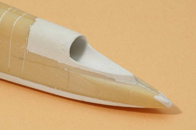
| A complicated improvement was the exhaust. The kit's exhaust looked too small to me, but I had no real photographic proof since all photos conveniently blocked that specific view! Fellow Firebee researcher Craig Kaston provided the key photo that allowed the reconstruction. This rear view photo showed the true size of the outlet, which is much bigger than all other views suggest. I guess this is no coincidence :-)
Reconstruction started with rolling a tube from super thin (0.05 mm) plastic card. Next I cut away a worrying amount of fuselage, aligned the tube as accurately as possible, and then reconstructed the fuselage shape with Milliput. The fairing behind the opening was filled to the 'pen nib' shape that I think I see in the photos. It's not finished yet though, and I also need to reshape the upper fuselage. Later I noted that the exhaust looks a lot like that of a Hawker Seahawk.
|
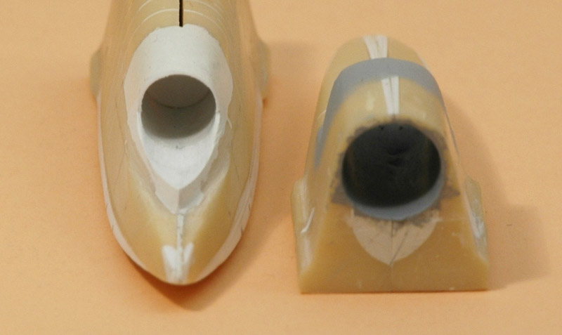
| One more view of the exhaust and the inlet duct. If you look very closely in the inlet, you will see that it still needs a bit of filling here and there.
| 
|
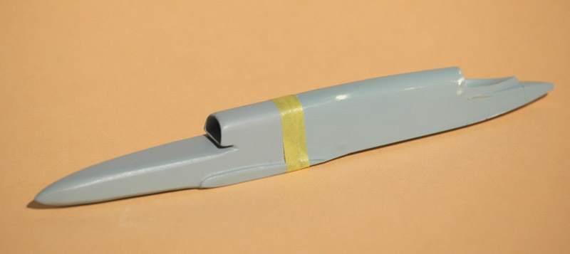
| The front fuselage still wasn't right. Its depth was increased, and the lower side made to curve upwards near the radome. After all these modifications I painted the two fuselage parts light gray, so the shape of the fuselage would be clearly visible, without distortion by the different colors used in its construction.
|
| With the fuselage now divided in front and rear parts, I noted that the alignment between the two was difficult to maintain. To solve that problem, I (laboriously) installed an alignment pin. First an oversize opening was drilled in both halves. Then I built a close-fitting plastic card box around the pin, and 'glued' that box in the rear fuselage with Milliput. After curing I repeated this in the front fuselage, after lots of checking of the alignment. I used the opportunity to add a slight angle in side view, to further reduce the 'banana' shape of the original model.
| 
|
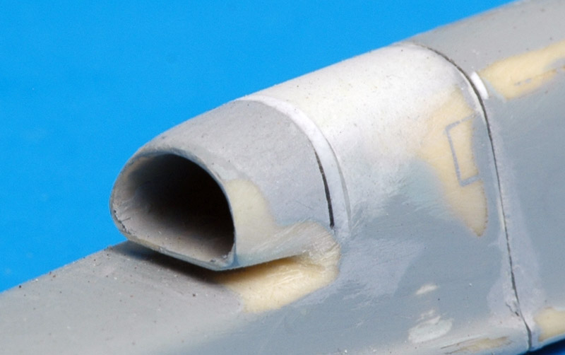
| The inlet required more reshaping. I made a subtle change to its upper contour with a strip of plastic and some putty. The inlet itself was rounded some more at its lower corners using Apoxie. Next step was to create a larger boundary layer bleed slot, both in height and length, using the JLC saw and sandpaper. Later, small vertical walls were installed 3 millimeters behind the inlet's lower edge. Lastly a smooth aerodynamic shape was created with more putty and sanding.
Not shown in the photo: the front fuselage required more reshaping, creating two facets along the lower edges. I had put off that task for a long time, fearing the difficult task of creating symmetrical facets. I think the wing roots need to move up a bit too, the wings currently attach too low to the fuselage.
|
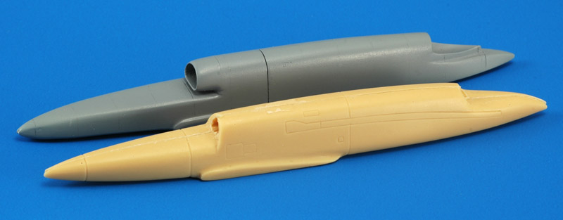
Comparison of the original and converted fuselages so far
| For motivational purposes it's always nice to compare the modified model to the original. The A+V model is really difficult to find (even on Ebay), so I was happy to trade a model, even though it's a horribly shaped model. I tacked the fuselage together with three small drops of CA glue for these photos. One observation with this photo is that I see less 'banana shape' than I expected.
| 
|
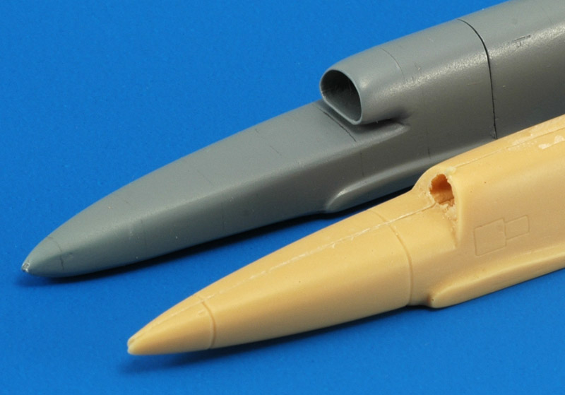
| The air inlet of the original model is close to ridiculous. I don't think I ever had to reshape a part as extensively as this one.
|
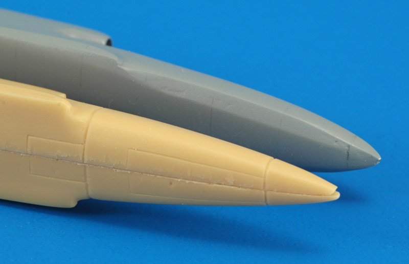
| In planform the nose was also badly shaped. Note that the modified model is not ready yet, it's a rough shape only.
| 
|
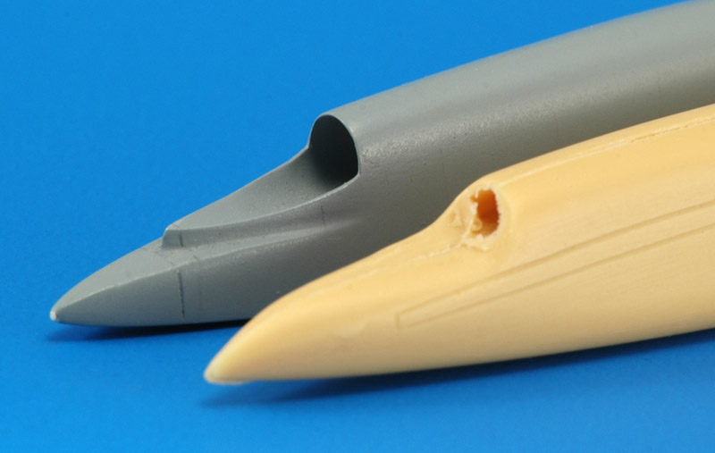
| The exhaust was a close second to the inlet in terms of ridiculousness. The whole area was rebuilt.
|
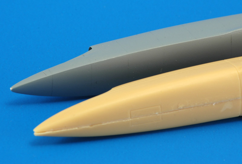
| Another hilarious mistake was the rounding of the rear lower fuselage. It makes you wonder whether the builder of the master model ever saw a photo of the real thing? Probably not.
| 
|
Wings
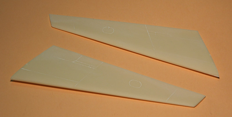
| The leading and trailing edges of the wings were sanded on a large piece of sandpaper to make them straight. The drawing showed smaller root and tip chords, but since I was unsure about its accuracy I did not modify the wing planform any further. The sanding operation had left square leading edge and thick trailing edges in places, so these required additional sanding. That in turn required some rescribing. The hatches were on the upper instead of lower wing surface (using the root to judge which side is up and down), and had to be rescribed too.
| 
|
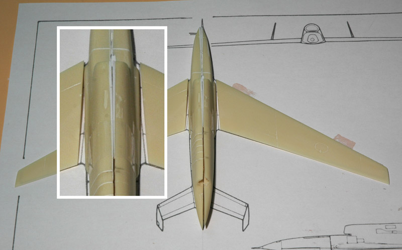
| I don't know how the wings fitted to the fuselage before I started to cut it up, but the photo shows that the fit was pretty bad after the modifications. The fuselage and wing parts are placed on the drawing from 'World Unmanned Aircraft', scaled up to 1/72. I will definitely use a jig to mount the wings to the fuselage.
The wings should be mounted slightly higher on the fuselage, so they are completely flush with the lower fuselage side. Possibly the root chord must be increased.
|
In 2021, I finally found the profiles used on the real thing, and calculated the profile data. This brings me one step closer to making a 3D model, and have the wings (and possibly tailplanes) 3D printed, to replace the A+V parts.
Colors
I found about 15 photos of the AQM-91 in five books, and only one color photo in 'Robot Warriors - The top secret history of the pilotless plane'. Luckily the latter was big and showed an interesting color scheme with black, white and bare metal, so I decided for that one. The one in the Air Force Museum is black overall by the way.
Research
According to this The Florence Air and Missile Museum display list, an AQM-91 used to be on display at this museum. I would love to know more about it!
Conclusion
I fear that you will not buy this model after reading my report. True, A+V Models should have made a much more accurate fuselage. But the subject is so eclectic that you don't have to wait for another model to come out. So if you want an AQM-91 on your shelf, there's no alternative.
Links
Video links
Starting 2013, the San Diego Air and Space Museum (SDASM) has posted many Teledyne-Ryan videos on YouTube. The following Model 154 / AQM-91 related videos were found so far, but there may be more. Note that the F numbers are assigned by the SDASM. Many movies suffer from severe color degredation, and quite a few are shown (partially) mirrored. The sound is often missing, or was never there. I corrected the titles when there were obvious errors.
F-0950 Teledyne Ryan Project 154 AQM-91A Compass Arrow Drone - useless desert scene
F-0953 Teledyne Ryan Project 154: Lockheed C-130 launches AQM Compass Arrow Drone - launch of black example
F-0961 Teledyne Ryan Firefly RPV/ Drone/UAV in flight - bare-metal AQM-91 drop and close-up in-flight
F-1011 Model 154 Tow and Dock - orange 154s under CH-3s
F-1033 Teledyne Ryan AQM Compass Arrow Test C-130 take-off, MARS recovery
F-1034 Teledyne Ryan AQM-91 Compass Arrow UAV Tow and Dock San Nicholas Island -
F-1093 Ryan Firebee Drone Footage, C-130 UAV - mainly Model 154 with Firebee history. Gray and orange 154 at the end
F-1234 Ryan Model 154 Drone - bare-metal AQM-91 drop and close-up in-flight
F-1405 Ryan Aeronautical Model 154 - MARS in slow motion
F-1406 Ryan Aeronautical Model 154 - under main chute
F-1407 Ryan Aeronautical Model 154 / AQM-91A Firefly - mass drop tests for MARS parachute tests
F-1409 Ryan Aeronautical Model 154 / AQM-91A Firefly - fuel system tests, dummy drops, airframe manufacturing
F-1458 Ryan Aeronautical Fire Fly 1970 [film] - bare-metal AQM-91 drop and close-up in-flight
F-1460 Ryan Aeronautical Model 154 Dune and Northrop Sites - drop and recovery filmed from ground
F-1463 Ryan Aeronautical Model 154 Low Speed Wind Tunnel Tests runs 18-26 - wind tunnel flutter tests
F-1464 Ryan Aeronautical Model 154 Low Speed Wind Tunnel Tests runs 18-26 - wind tunnel flutter tests
F-1465 Ryan Aeronautical Model 154 Low Speed Wind Tunnel Tests Flutter Model
F-1505 Ryan Aeronautical A68-266 Fire Fly (AQM-91) 7/12/1968 - parachute landing of orange example
F-1506 Ryan Aeronautical A68-160 Fire Fly March 1968 CH-3 hauling an orange 154 with airbrags out around. No markings on the 154
F-1678 Ryan Aeronautical Drone Preparation at Holloman Air Force Base - preparations for display - demating of 154 fuselage, white 154, orange 154, engine removal
F-1680 Ryan Aeronautical Drone Preparation at Holloman Air Force Base - 154 camera work
F-1792 Ryan Demonstration or Compass Arrow Elements Model 154 / AQM-91A Firefly - in-flight, pylon mounting, drop, RCS test, recovery
F-2180 Ryan Firefly Mars Tests - CH-3 MARSing a white AQM-91 with an orange right outer wing
F-2310 Ryan A68-266 Fire Fly 7/12/1968 - parachute landing, two different views
F-2390 Ryan Military Recon Compass Arrow Weapons System - general introduction, with Firebee history (with sound)
F-2487 Ryan Fire Fly C-130 - DC-130 flying with two AQM-91s
F-2509 Ryan Firefly Testing - launch and landing of AQM-91, bare metal plus white with black outer wings and tailplanes
F-2595 Ryan Firefly 6/20/1968 Flight Tests - white and orange AQM-91s under DC-130
F-2641 A70-181 Fire Fly 6/5/1970 Early Ryan UAV Fire Fly Test - bare-metal AQM-91 drop and close-up in-flight
F-2731 Ryan AQM-91 Firefly UAV Tests - white and orange AQM-91 in flight, MARS recovery
F-2758 Ryan Compass Arrow - all phases of AQM-91 flight, pole RCS testing, plus U-2 component testing
F-2759 Ryan Compass Arrow Launch from C-130 - bare-metal and black AQM-91, launch, flight, parachute landing
F-2782 Ryan Aeronautical hanger testing AQM-91A Compass Arrow - pylon mating and test drop in hangar, outdoors mating, fuel test, hangar vibration test
F-2783 Ryan Aeronautical flight testing AQM-91A mock-up - CH-3 flying around with orange shape
F-2785 Ryan Aeronautical hanger testing AQM-91A Compass Arrow - launch, flight and recovery of black/white/metal 'P-4'
F-2787 Ryan A68-213 Fire Fly 921-68002 4 18 1968 UAV - pylon mounting, fuel test, drop test
F-2795 Ryan flight testing AQM-91A Fire Fly etc ground recovery - ground-filmed MARS recovery with problem, recovery with digging for nose
F-2828 Ryan MARS operations AQM-91A UAV - MARS recovery of FTV-5, bare metal with black right and orange left outer wing
F-2830 Ryan UAV Impact Area - parachute landing of a burning AQM-91A
F-2831 Ryan AQM-91 Flight Ops UAV - wet recovery practice
F-2840 Ryan UAV P9-8-69B launch & Past recovery 8 25 1969 - ground-filmed launch and landing, recovery, film title suggests P9
F-2951 Ryan Firefly WSC-76 Launch, chute deployment, ground impact - flight and parachute landing of AQM-91, bare metal plus white with black outer wings and tailplanes
F-2954 Ryan Firefly P4-4-9F WSC-122 9/6/1969 - launch and flight of bare metal AQM-91, film title suggests P4
F-3050 Ryan tracking launch flight ops AQM-91A 9/22/1969 - ground view of launch and flight of bare metal AQM-91
F-3052 flight & recovery ops AQM-91A from Lockheed C-130 - launch, flight and recovery of black/white/metal bird
2830 3022 3608 3822 3837
Return to models page


