| After quite a lot of research, that even resulted in an AQM-34 web site, I decided I had enough information to start a conversion. Of the many versions, I selected the AQM-34L as the best one to start with, since this is a version that would easily allow further modification into other versions. I converted a BGM-34C drawing into one of an AQM-34L, and went ahead. Research continues however, since there are still a lot of interesting versions that I possibly want to build later. |
It took me quite a while to find the Italeri Firebee(s) shown below. The 1/72 DC-130 is long out of production, and difficult to find. I was about to trade some Firebees with American modelers, when we (fellow modeler Tjepke and I) visited the IPMS-NL 2002 Nationals. And there it was: a partly-built 1/72 DC-130, for only 5 euros! The Firebees were unbuilt and on their sprue, just perfect. It was our find of the day of course!
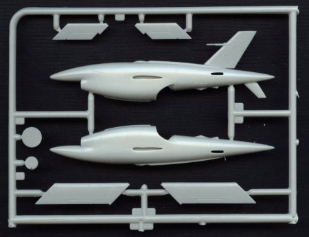
The Italeri Firebee model consists of eight components, with raised panel lines. You get four in the 1/72 DC-130 kit, and probably the same number in the 1/48 version. Decals are also included. As far as I can see now, the Italeri Firebee model is very accurate for a seventies/eighties Firebee (for current models you need to cut back the air intake, and give the radome a nose-up attitude). They even captured the weird wing section. Only the area around the exhaust needs some reshaping, and the bulged fairing under the rudder is missing.
The basis for this conversion is the BGM-34C drawing from the SPIE proceedings. It appears to be completely accurate; I haven't found a single problem yet. It agrees very nicely with components of the (shorter) Italeri BQM-34. The nose section of the BGM-34C is unique to the BGM-34C and the AQM-34V. The noses of other (earlier) models are all smaller. Work is under way to establish the contours of these earlier noses. In the meantime, the BGM-34C drawing will serve as the basis of the conversion of the rest of the airframe.
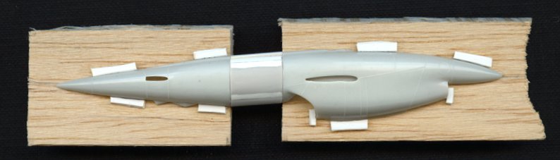
I started by inserting a 35 inch plug (translating into 12.3 mm) in the rear fuselage. The plug is slightly complicated by the fact that it slopes down some 4 degrees, yet has vertical ends. To ensure alignment of the component, I made a little jig for the operation, using a piece of balsa wood with plastic stops superglued to it. The balsa wood was then cut along with the fuselage part. The jig parts were then aligned against a steel ruler, with the right-hand jig displaced some 0.8 mm upwards (being the tangent of 4 degrees times 12.3 mm). I used a 1/48 scale MXU-648 USAF travel pod (from a Hasegawa 1/48 F-16) as the source of the plug. After fixing the plug with CA glue, I noted that the Firebee's rear fuselage was elliptical instead of round. I had to add plastic card strips at the top and bottom, and perform some sanding on the sides.
The other (left) fuselage half was cut in two, and spot-glued to the right fuselage half. This would ensure two fitting fuselage halves. After fitting of the plug to the left fuselage half, I broke the glue spots and I had two fuselage halves again. The fuselage plug looked pretty 'natural', so I guess the BGM-34C drawing was very good in that respect.
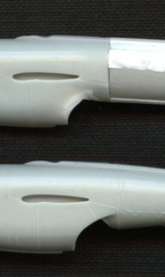
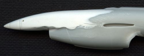
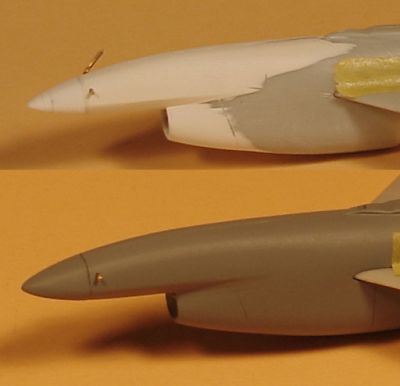
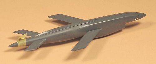
After looking at the many walkaround photos on the AQM-34 web site, I had gained a good idea how to improve the rear nacelle area. I glued plastic card to the interior of the nacelle, to allow vigorous scraping and sanding. The rear end should curve inwards on the sides, and the nacelle's exhaust opening should be some 2 millimeters narrower. Also, the area directly behind the exhaust (i.e. the lower side of the fuselage, just ahead of the fuselage plug) needed considerable reshaping. Lots of gluing, scraping and sanding it looked like in the photo below. The shape is close, but not perfect yet. A coat of paint will be needed to judge the progress better. The photo also shows that the left fuselage plug is not yet finished.
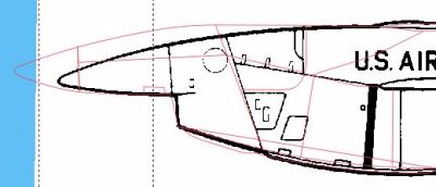
Next was the nose, the most complicated part of the conversion. I superimposed my AQM-34L drawing over that of the BQM-34A nose, which gave a basis for the reshaping. The rest will be based on lots of photos.
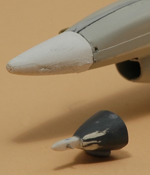
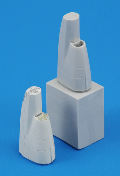
Shown below is the first version of the nose modification. I glued a 'radome bulkhead' to the tip of the BQM-34 nose, and built up the front fuselage with Milliput. The wavy lower edge of the thickening will be taken care of later. The radome itself is laminated plastic card. The contour appears reasonably correct, but the plan form still needs considerable reshaping. But at least it starts to look like an AQM-34L now!
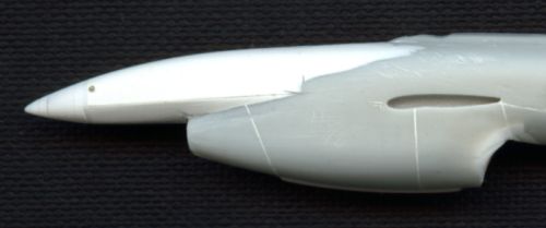
Second step of the nose job. Barely visible is that I cut back the 'radome bulkhead' because the model didn't agree perfectly with my drawing. Well visible is that I sanded the lower side of the nose into shape, three facets to be more precise. The large collection of Firebee photos proved to be invaluable for this sculpting job.
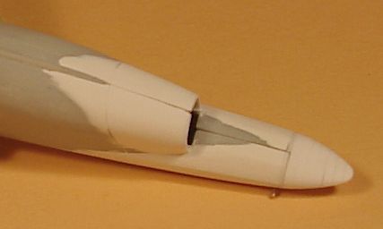
With the new nose more or less correct, I could move on to some other items. I always thought the inlet looked fairly small (note that the AQM-34 inlet is the same size as that of the BQM-34A). Measurements of photos confirmed that it is undersize. I calculated that both the width and height should be increased by 1 millimeter. I glued an 0.5 mm strip around the inlet, and used Milliput to fair in the new inlet edge. A rat file was the used to file away the original plastic. At this point I took the photo shown below. The inlet was now 1 mm wider and 0.5 mm taller, and frankly it looked too wide. I installed the boundary layer bleed slot, but the inlet shape still looked wrong. I modified the inlet again, changing it from a simple 'D' shape to the something best described as the lower 60 percent of the figure '8'. It now looked very much better. I also sanded the air inlet edge a little to give it 1 or 2 degrees of backward slant, as seen in photos and some drawings. I am now working on the inlet duct inside the fuselage.
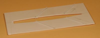
I found yet another modification that needed to be performed: the tail cone should be lengthened. The tail cone consists of two parts, a large forward part that contains the main chute, and a small rear part, that probably contains the drogue chute, or the brake chute. My best guess is that later models of the Model 147 had a larger tail cone to house a larger parachute than the original BQM-34A. I noted it because the Model 147's tail cone has a slight kink at the transition between the forward and rear parts of the tail cone. From studying photos I concluded that the division of the forward tail cone and the rearward tail cone lined up almost exactly with the trailing edge of the tips of the horizontals. This presented a small problem, since the positioning of the horizontals in the fuselage is very vague. I saw no other solution then to build a simple jig first, that would ensure perfect 45 degrees alignment of both the wings and the horizontals. I built it from 2 mm plastic card and four strips of plastic card (and some patience). You can see the penciled outline of the horizontals on the jig, used to measure the required tail cone elongation.
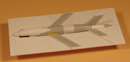
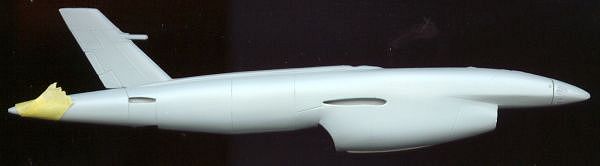
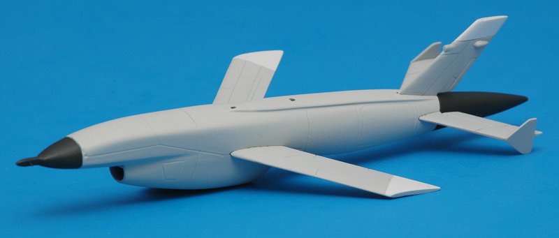
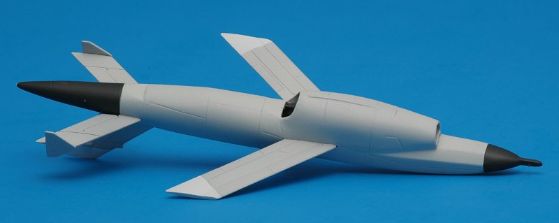
The model placed in the jig, with all flying surfaces added. It was the first time I saw the complete model, and I was impressed! It was much larger than I expected, and it really looked like an AQM-34 now. The photo shows the white extended forward tail cone. I cut the tail cone on the panel line, glued a 2.5 mm long spacer on it (a 4.8 mm diameter torpedo part from the spares box), and used Milliput to create a simple straight cone from the rear fuselage to the end of the forward tail cone. Then I glued the small rear part on again.
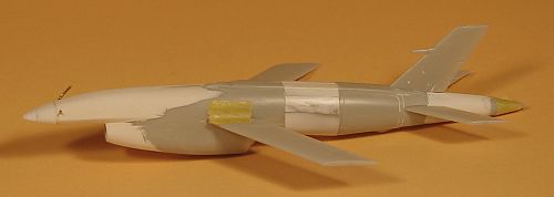
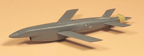
The result so far can be seen below. The fuselage is nearing completion, and pretty soon I will spray it in some neutral medium gray color. This will allow a much better check of the shape and symmetry than the current mixed color model does. If you're wondering what the piece of brass wire is doing in the nose: to keep the model castable, I need to build it in two halves, and to keep it properly aligned during construction, I drilled a 0.5 mm hole in the nose, with a brass wire as a 'locater pin'.
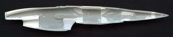
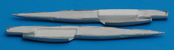
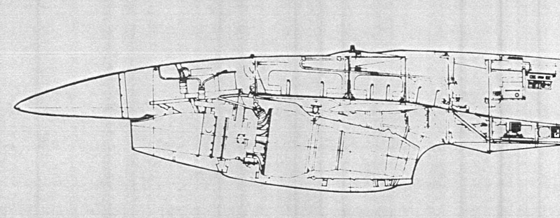
An interior view of the right fuselage half, showing many of the modifications described earlier. Working from the front to the rear: the built-up nose, the inlet duct leading to a 5 mm diameter engine compressor (boundary layer splitter lip just visible), the modified nacelle exhaust, the fuselage plug, and lastly the extended tail cone.
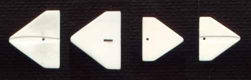
The AQM-34L flew with two types of endplates on the horizontal tail planes. They had identical shapes but different dimensions. I built up one each from three layers of 0.005" plastic card. On the 'inboard' layer I left out the tip profile, so the endplate is correctly located during installation. On the large endplate I installed a tiny rod, this is an indicator for the tail plane deflection, used during pre-launch checks. On the small endplate I left it off for the moment because it projects behind the endplate, and would get damaged too easily.
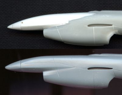
I was not completely happy with the nose shape, it looked slightly too flat and pointy. I decided to make it slightly thicker on the top side. I glued 0.5 mm thick strips of plastic card on the centerline of the model, and feathered its thickness to nothing near the canted panel line seen in photos above. Milliput was then used to build up the rest of the nose. At the same time I lengthened the radome slightly, and performed a similar operation with strip and Milliput. After this operation, I sprayed the model in a medium grey, which makes it easier to judge the shape. Initially I thought I had captured the shape now, but after a while I started to see some problems again.
And so I performed a third nose reshaping. The contour of the upper front fuselage was changed again, making the nose fatter one more time. The radome bulkhead was moved back 0.3 mm and the radome lengthened accordingly. Like before, I thought I had achieved the correct shape. The next step was a general cleaning up of the whole model, with lots of small putty jobs, rescribing and sanding. After another grey base coat, the model looked better than ever. It's now time to scribe the front fuselage.
My friends are referring to my model as 'Michael Jackson', since I again got doubts about the nose shape. A fifth nose job was performed, moving the radome bulkhead upwards half a millimeter, so I could give the lower nose a very slight curve. The upper side was built up again with Milliput, and the result was a slightly bulkier nose, just as intended. To show that I'm not a total nerd about the nose, the photo below shows the nose in its initial shape, and after the fifth reconstruction. The differences are obvious I think. Let's say it has been an interesting experience to shape something from photos.
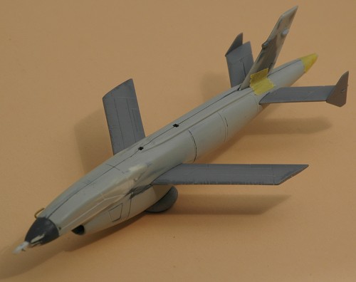
The vertical tail was removed from the left fuselage half, since its presence made future casting much more difficult. I would have been removed it anyway, since it is not placed on the centerline of the model, but more on the left fuselage half (bad Italeri!). The removal also allowed a very slight backwards tilt of the vertical tail, something on which most drawings agreed. The fuselage was then combined with the wings and horizontal tail planes for the following photos, that should show how much progress the fifth shape change brought.
I hope to make a few extra copies of this model, and for starters I made a mold for the wings, horizontal tail planes and their endplates. I used a 10 Shore-A silicone rubber and cast the parts with tinted SmoothCast 310.
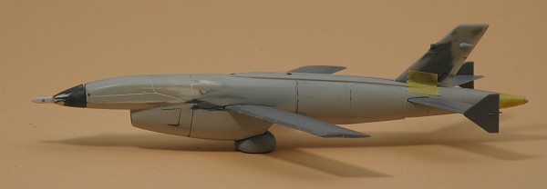
Work continued slowly, and the photos below show a number of small upgrades. The fuselage was repainted in yet another shade of gray, the front side was scribed and some panel lines of the rear fuselage were improved. The model is now fitted with resin wings and tailplanes. Experts will notice the small endplate on the right tail plane, and the large endplate on the left tailplane. The radome was fitted with a square cross section 'spike' with an AoA sensor made of a needle tip. The vertical tail still needs a lot of work.
Work was also started on an AQM-34M radome. The photo below shows the separate L radome, and a rough version of the M radome attached to the fuselage. It will eventually get the same 'spike' with AoA sensor. The M version will also require lengthened wings and possibly fuel tanks.
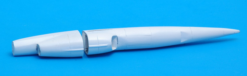
The next step was a switch to a fuselage divided in front and back instead of left and right. Since I removed the vertical tail, the castability of such a fuselage looks much better. I plan to cast copies of the separate fuselage halves first, as a back-up. Shown below are the masters ready for making a silicone rubber mold.
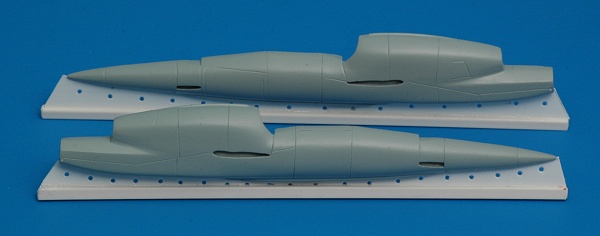
First I cast epoxy resin back-up masters, and then some extra polyurethane resin copies of the fuselage, wing and tail parts. The latter (shown below) are just for fun, since the masters still need some work and modifications.
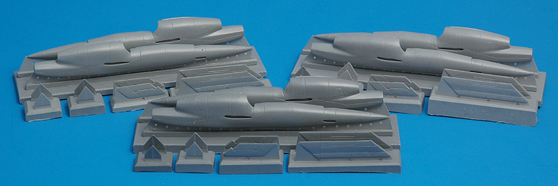
One set was assembled into a preliminary version of the model. It still lacks a number of details, but it gives a good idea of the overall shape. Most likely the standard color of AQM-34Ls was FS26492, slightly darker than the FS36622 used on the DC-130 pylons. Suitable paints are Model Master 2038 (FS36492) and Humbrol 196. Maybe a 1:1 mix of Humbrol 166 and 196 is an even closer match, but that might be only true for the two tins that I have.
Work then continued on the masters. I learned from my A&V Models AQM-91 project that having a solid alignment pin between the fore and aft fuselage halves makes life a lot easier. In the AQM-91, I installed it afterwards with considerable trouble. Here I could do it much easier. I took a piece of brass rectangular beam, and built close-fitting plastic card box around it, without bonding the brass to the plastic. I then filled the two fuselage halves with Apoxie putty, embedding the plastic box in the position where I want to cut the fuselage later.
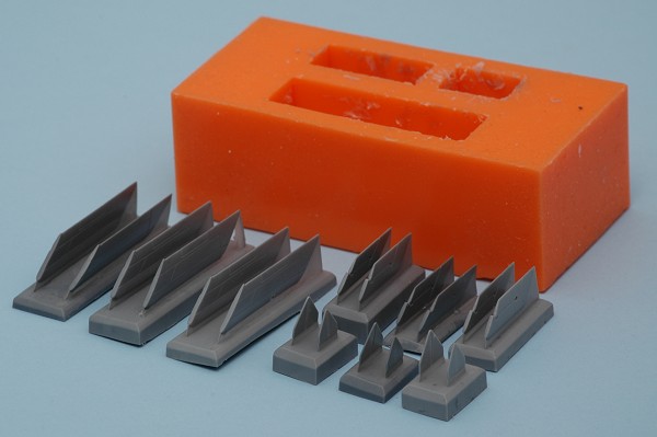
Apart from the short AQM-34L radome, I built a longer and upturned AQM-34M radome too. Together with the vertical tail master part (very much unfinished) I cast a new mold and some resin parts.
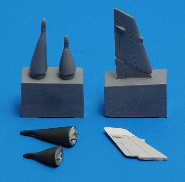
The assembled resin copy shown above showed that I still have quite a long way to go with the master parts. Especially the panel lines: they are inconsistent in depth and width, and symmetry is not always perfect. I'm tempted to abandon the scratchbuilt version, and switch to a 3D printed model. But creating the CAD model isn't easy with so few dimensional references. To be continued.
As a test I assembled another fuselage, then cut it just ahead of the wing, and filled both halves with epoxy clay. A cut just ahead of the wing completed the change from left-right division to front-back division, something that I wanted to try from a casting point of view. The test of the front half was promising. I think it would be smart to include the radome in the casting in the final product.
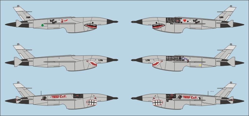
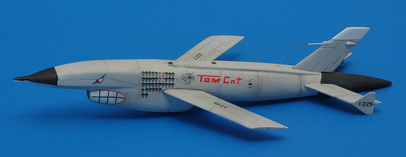
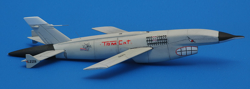
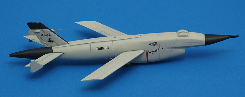
I'm slowly designing decals for the model. Only a few Firebees were photographed in sufficient detail to allow the recreation of their markings, but fellow Firebee researcher Craig Kaston and photographer Mark Nankivil helped out big time. So far I've done L-174 'M.R. Ling', L-223 'Baby Buck' and L-229 'Tom Cat', all Vietnam veterans with lots of missions and big sharkmouths, shown below. It took a long time before I found out what stencil was used to make the lettering on Vietnam Firebees. I spent a lot of time on Ebay studying old stencil sets being offered. After some time I found the answer: they were made with 4 inch 'Reese's Adjustable Lockedge Brass Stencils'. Other Firebees markings that I am working on are M-42L, LTV-250 and TV-50.
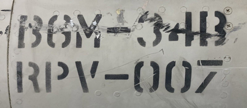
I'm now looking for yet another stencil-type lettering, that was used by either Teledyne-Ryan or the Air Force on the BQM-34A target Firebee, and the armed BGM-34B. I find the 'B' quite typical, in that the left-hand vertical stripe has two very small extensions toward the right-hand '3'-shaped part of the stencil. You don't see that in any other stencil. Also, the gaps in the letters are slightly larger than with other stencils. In this particular application, the stencil appears to be 1 ¾ inch tall. One promising lead is that it is made with a 'Marsh Stencil' machine. Marsh produced stencils cutters for the following sizes: ¼, ½, ¾, 1, 1 ½, 1 ¾, 2, 3, 5, 6, 7, 8, 9, 10 inch. Unfortunately, it seems that each size has slightly different letter / number designs! Look closely at the 'A' letters for example in the product display photo. I think all stencils larger than 1 inch were made on a 'Super Size Stencil Machine' with a roller than runs over a large board with 'cutters'.
It could also be a Diagraph machine. Diagraph seems to be the only one with a the slight extensions of the left-hand bars of the B and D. But whether they did a 1 ¾ inch stencil machine in the past?
Diagraph Bradley Industries Inc Jumbo Model Letter Size 1 3/4" Stencil Cutting 3 rows of characters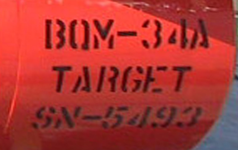
Having an abundance of resin copies of the master model changed my approach quite a bit. Note that the masters are not finished yet, so the resin models lack quite a few details (like camera windows) and have some crooked panel lines. But it's an easy model to assemble, so it takes little time to build another model. I decided to slap a few together to serve as test models for the decals. No need for perfection.
'Tom Cat' was of course the first one that I built, since I had spent ages on the design of the decals. The model was painted Humbrol 196 overall with a black tail cone. The decals were put on a bit too enthusiastically, which led to quite a bit of silvering. After a thick coat of satin varnish (Humbrol 135) I did a bit of weathering with water colors. The radome and vertical tail were not glued on because they were master parts that still needed to be cast. The finished test model was then used to evaluate the decals, helped by my modeling friend Eric. It turned out that all except one decal required some changes or corrections. It was clear that designing decals on a flat screen is quite a bit different from viewing them on a three-dimensional model.
I painted the radome in two colors, but found out that masking such a tiny part is not easy. An 8 mm pitot tube was added to the vertical tail, made from 0.4 mm Albion tube and 0.2 mm steel wire, each 4 mm long. Note that the kit's pitot mounting base was still too large, I changed that on the next model, 'M.R. Ling'. I also added a 4 mm long whip antenna on the spine, from 0.1 mm nickel-silver wire. Still to be added are elevator indicators in the endplates, and the model should be glossier.
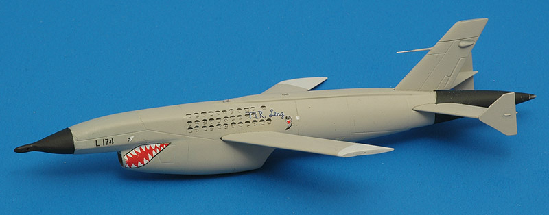
Secondly I built 'M.R. Ling' as on display in the USAF Museum. This one used bigger endplates on the horizontal tails compared to Tom Cat. The real aircraft used longer wings, but I had not built those yet. By accident I painted this model the wrong color, Humbrol 166 instead of Humbrol 196, so it looks a bit brownish. Judging from photos, the museum example has the left side of the nose overpainted, with a color that could be FS 26473. I applied that color on the nose (in the form of Humbrol 146), but it hardly shows. Having learned my decal silvering lesson with Tom Cat, I buffed / polished the paint before applying the decals, and this time they went on without silvering. Unfortunately I placed the decal with the mission markings a bit too high on the fuselage. The vertical tail is painted like it like the museum original, where it appears to have been overpainted. The tail is fitted with an experimental pitot tube built from the fantastic Albion brass telescopic tubing. But I still have to establish the correct diameters of the real machine. The model is not yet weathered, which makes it look quite toy-like.
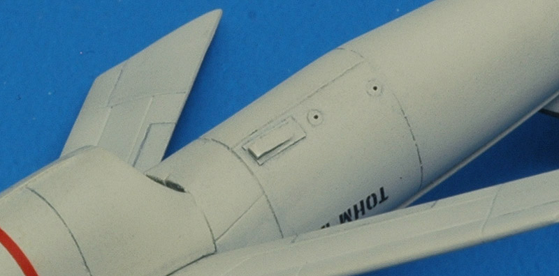
I used the third model to build M-42L. First I had to finish the AQM-34M airframe modifications, starting with the weird upturned ('ski') radome that I had started earlier. It took a few rounds of filling, sanding and painting to get it right, ready for casting. Next I built the film reel bulges on the nose topside. I found a tube of 8.5 mm diameter that seemed the right size, and cut two segments from it. These were sanded until they were 1.5 mm high, and then glued to the fuselage. However, compared to photos they still appear to be too tall. And even worse, M-42L did not have them, I found out later. I thought the bulges were a standard feature of AQM-34Ms, but they aren't. Third modification was an intake and two antenna base plates on the right side of the rear fuselage, shown in the third photo, but still lacking to antenna rods. Lastly I modified a set of resin wings to create wings with extended tips. Preliminary calculations showed that they were 3.0 mm longer, and I attached wingtip segments cut from another set of resin wings (visible in the first photo). The model was then painted, decaled and weathered, but I didn't yet make it glossier, it's too flat now (it was overcoated with Alclad Klear Kote Semi-Matte later). I'm very happy with the black 'Buffalo Hunter' logo on the tail, a buffalo with a cartoon Indian with bow and arrow sitting on its shoulders, looking the wrong way for prey. Still to be fitted is a total temperature sensor on the right front fuselage (the hole is there though). Potential kit donor parts are the Hasegawa F-104G (part A19), Hasegawa F-4 (part P9) and Revell of Germany F-16s.
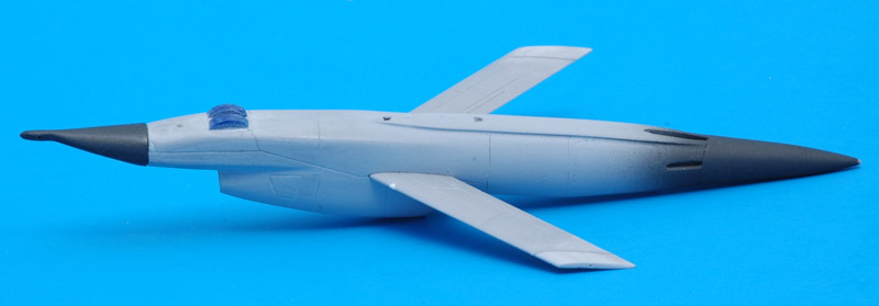
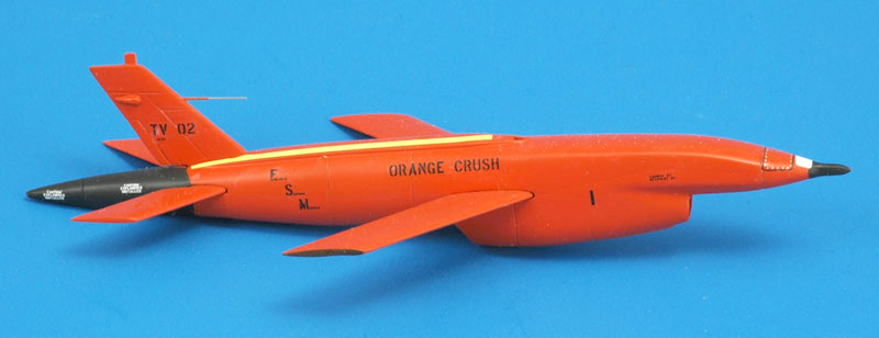
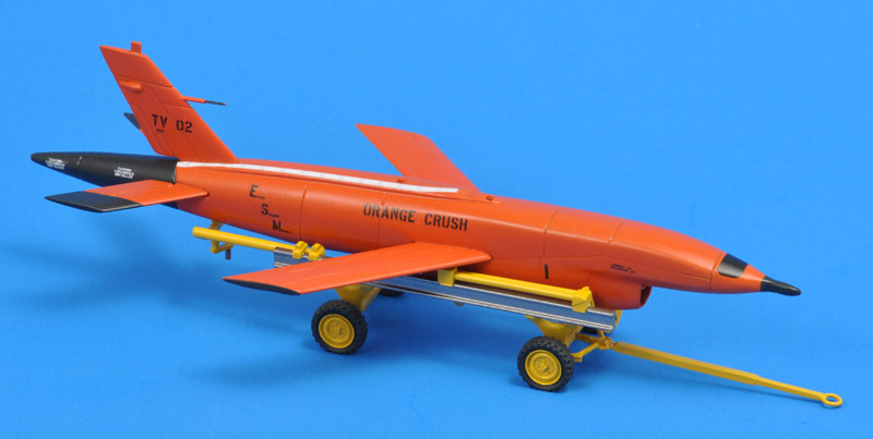
Another decal set that I designed was for Orange Crush, a training AQM-34K from Davis-Monthan and Hill AFB. What you see below is the second one that I built - I wasn't happy with the first one painted with Humbrol paints. After all the gray Firebees, and it was really nice to do an orange one. I approximated FS 12197 International Orange with Mr Paint, mixing 232 (International Orange BS592) with 299 (Insignia Red FS11136) in a 15:1 ratio. After applying the Alps decals, I reduced the gloss with Alclad ALC-311 Klear Kote Light Sheen, to create an appropriate scale glossiness. As an experiment I added decals for the radome: a large hatch with fasteners and small hatch in white. The former does not look right on the model. Another test was the nylon strap that runs in a slot in the spine fairing. I printed it in yellow, which contrasts nicely but looks unrealistic. I also added the MCGS antenna at the top of the fin for the first time. The pitot is a first try with Albion micro tubing, with 0.4 mm tubing with 0.2 mm nickel-steel wire inserted. I probably made the latter part too long.
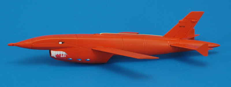
More decals to test: the small set for TV-50, a training AQM-34L of the 6514th Test Squadron, that was all-over orange at one point of its life (I overlooked the last section of the parachute cones). The Alps is not very good at printing color gradients like that behind the shark teeth. Apart from that, I think the decals look like the photos of the real thing, so I'm happy. The model was painted similarly to Orange Crush. I skipped the pitot tube on this model, because it was mostly a decal test.
I had one more model to use for decal tests, and decided to quickly slap an L(TV) together, by sanding off the nose spike and drilling a 1.5 mm hole. I had to choose between LTV-250 'Buffalo Chip' or LTV-217 'The Flying Circus Too' and picked the first. I printed the parachute strap brown-ish this time. Paint was again Mr Paint, an approximation of FS 26492 by mixing 98 (Light Gull Grey FS36440) with 246 (Light Arctic Grey FS36628) in a 2:1 ratio, and Alclad ALC-311 varnish. I skipped the pitot tube again.
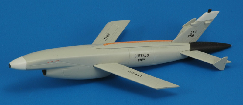
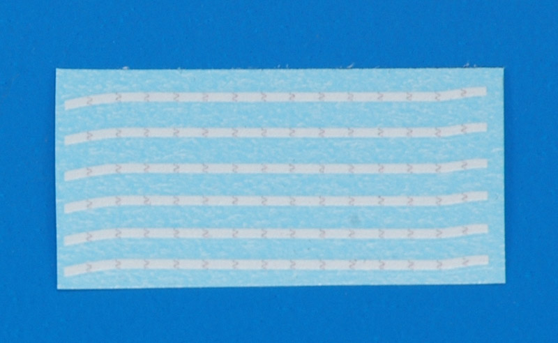
Another improvement that I tried was better parachute risers, that I had made yellow or brownish in previous experiments. I made them light gray with spring steel retainers across them. The decals turned out quite nice.
The next Firebee I built was a second copy of Orange Crush, for its crew chief Rich Saulnier. I added an Air Logistics 3000 trailer, the construction of which can be seen on the aforementioned page. The white parachute riser decals were used on this model. It's quite a colorful set now, rather different from all the gray Firebees I built so far.
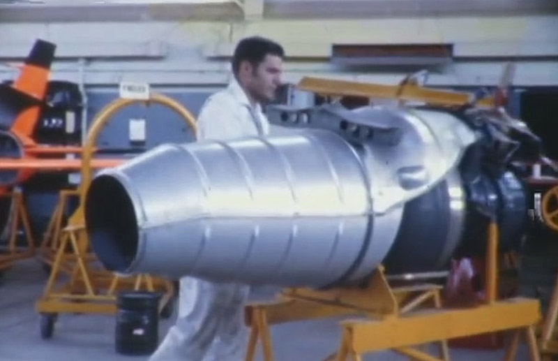
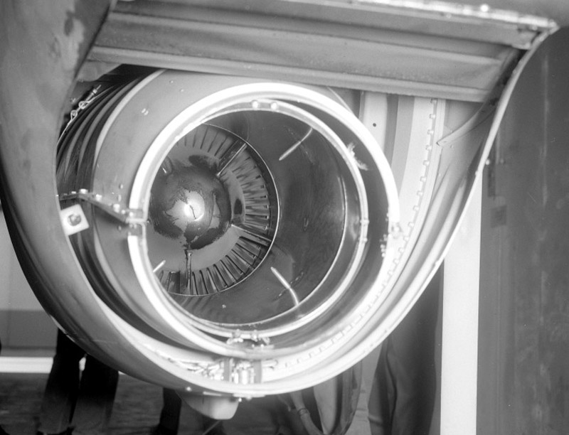
My model still does not have an engine exhaust. In the mean time I found a few photos that show the J69 exhaust and the heat shield around it. They are from F-3076 Ryan Firebee Construction, Flickr - SDASM archive and 'SDASM 2-11733' respectively.
To be investigated: were long wings always combined with large endplates, and whether a tail bumper part was used operationally.
Although the model isn't finished yet, I can already say that I had a lot of fun with a model that cost me only 1.25 euros! If you want to know more of the 1:1 version, please take a look at my AQM-34 web site