I had planned to make 2024 a test year for 3D printing, with questions like whether it's time-effective, is it fun to do the 3D CAD, and are the printing results satisfactory? Another goal was the get a much better grip on those nasty supports that are required for resin printing. They often ruin pieces because their removal results in too much damage. That last goal was mostly achieved by learning to work with the slicer software, in my case PrusaSlicer. Another tool that I learned to use is UV Tools, that can be used to check for 'islands', 'resin traps' and other possible printing problems.
the time spent on a 3D CAD model is likely to be half or less than scratchbuilding it the classic way, with better results in terms of accuracy and symmetry. But it still eats up a lot of time, and all that time you're away from the modeling desk, and that really does not feel good. You'll spend a lot of hours sitting behind the computer
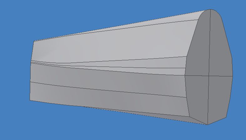
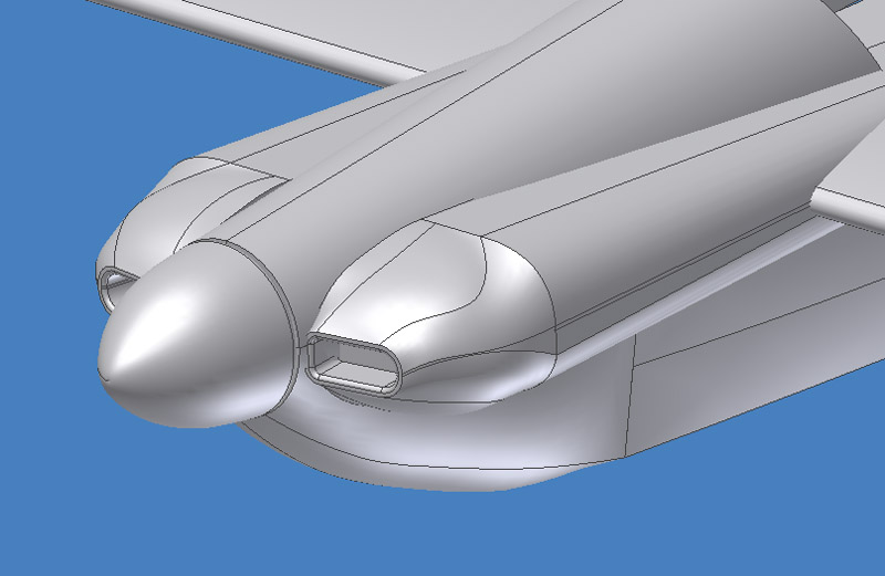
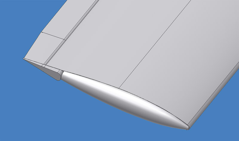
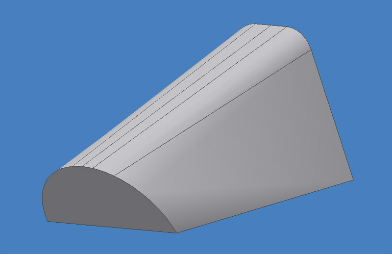
I found it difficult to judge the size of your parts when designing it on your computer screen. If you give the parts a minimum thickness of (say) 0.3 mm, it looks very 'clunky' on-screen, unacceptable clunky even. In reality, after printing, it generally looks OK though.
one remarkable problem was that my sleep was disturbed if I would do 3D CAD until late at night. I would 'continue' to do 3D CAD in my sleep. First impression is that a 2 hour gap is the minimum required to avoid this
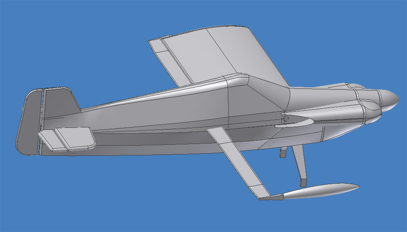
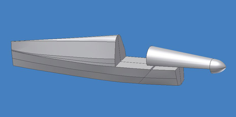
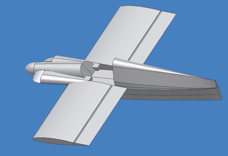
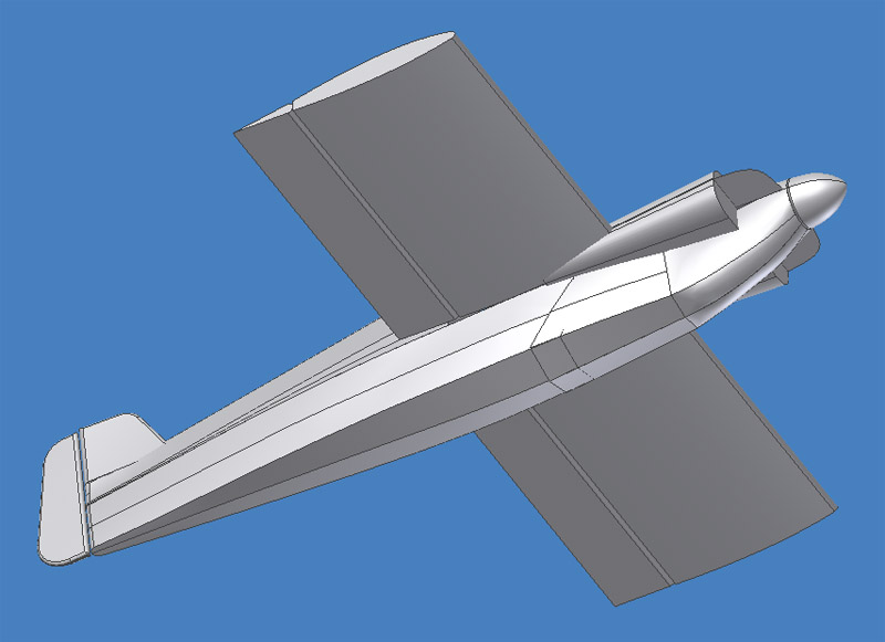
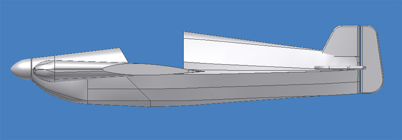
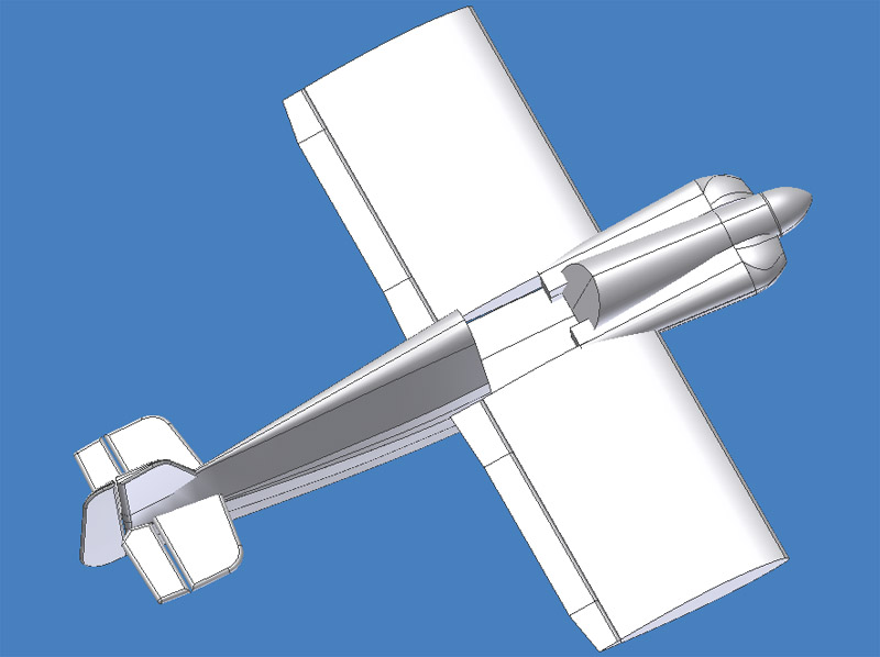
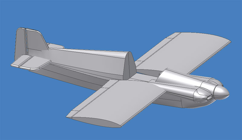
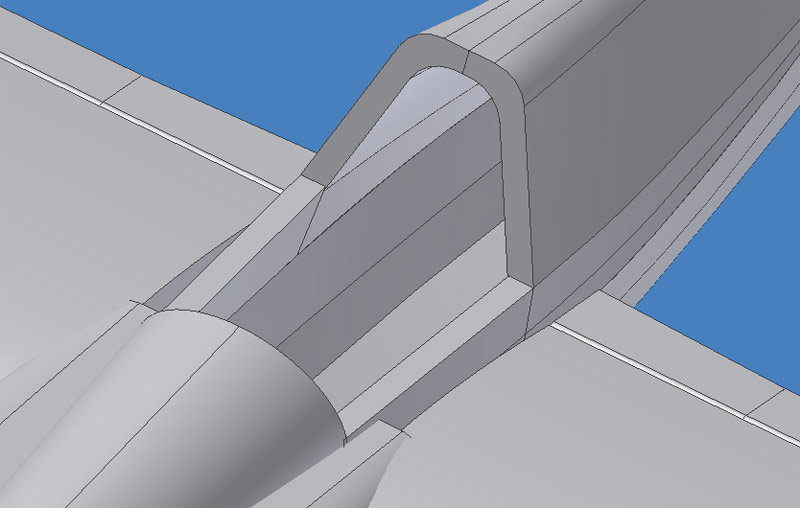
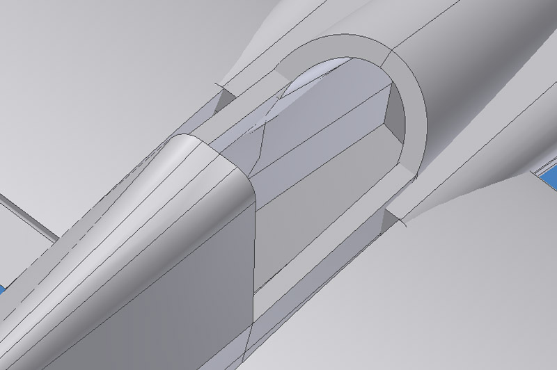
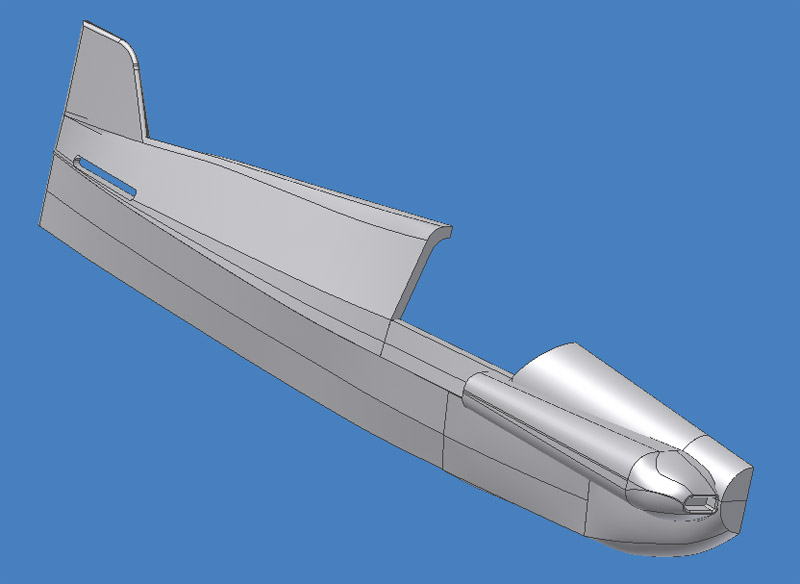
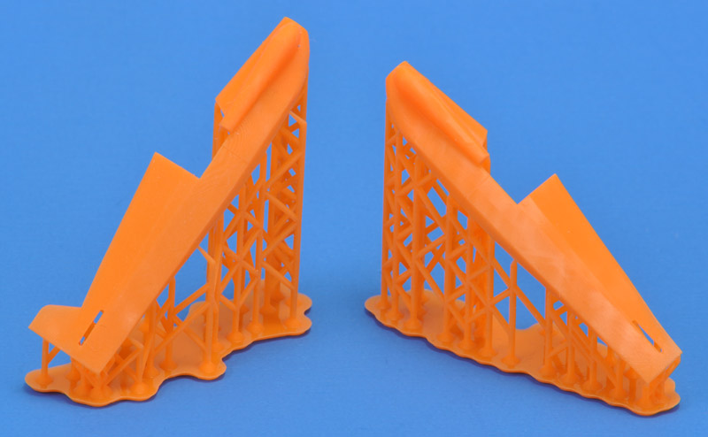
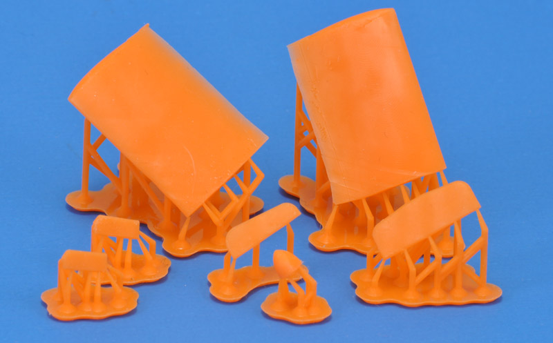
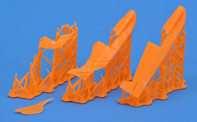
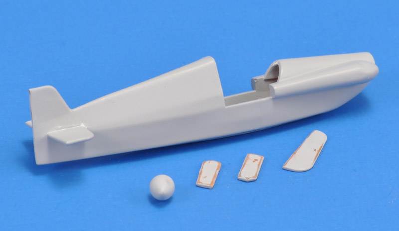
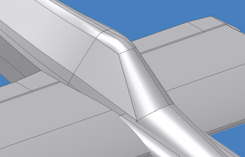
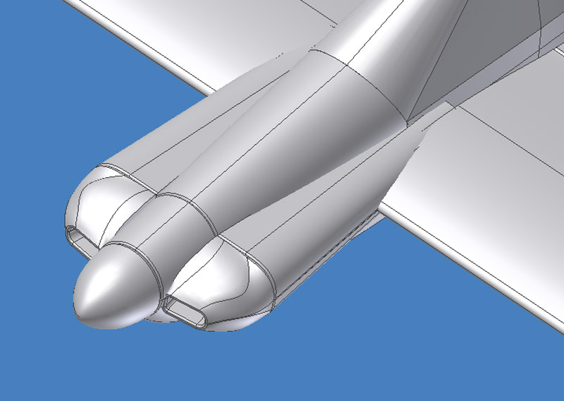
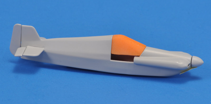
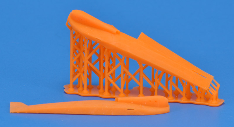
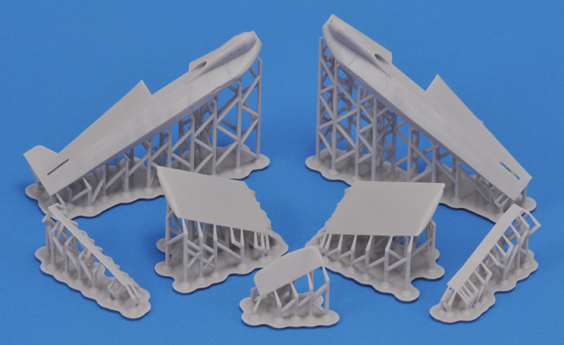
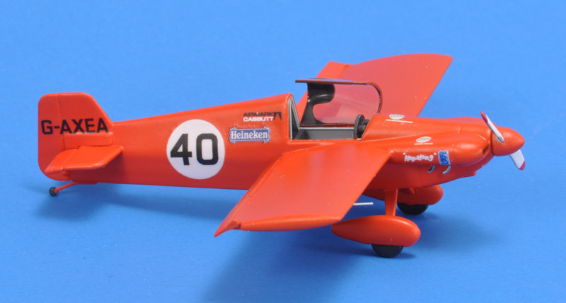
I split up the Cassutt model much like a conventional model kit, for many partial reasons. I wasn't too familiar with the printing aspect, and several parts meant spreading the risk of failed prints. Separate parts allow corrections during assembly; consider a wing that would have been printed at 88 degrees instead of 90 degrees to the fuselage. I am thinking of building more Cassutts, all with differences (because they are home built a/c) . I planned to mix and match parts to build a specific Cassutt, and that required separate parts. The supports were another good reason for splitting the model. Take the fuselage sides: I made the supports connect to the glue surfaces, so there are no scars from the supports on the fuselage. If I had done a single-piece fuselage, at least one side would be scarred. Lastly, I like the way normal scale models are split up. I would not enjoy a single-piece printed Cassutt.
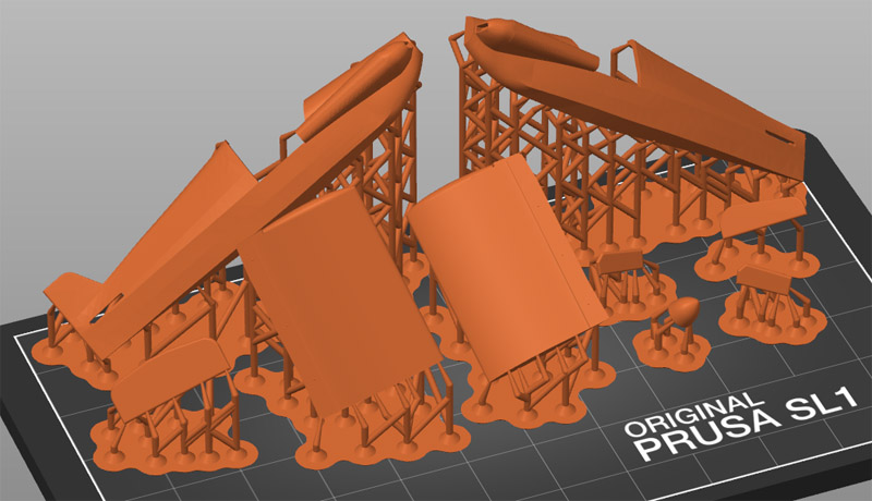
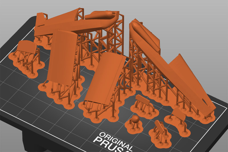
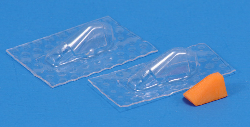
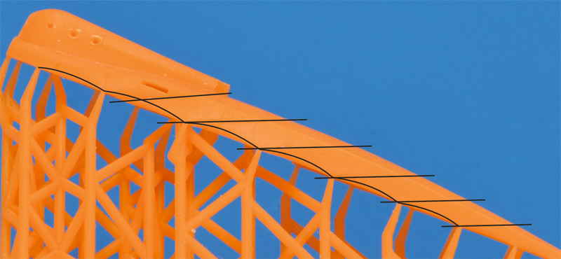
The supports were a fairly big problem in this project, partly due to my inexperience. I started with few supports, and ended with many, due to printing problems. I'm amazed at how few supports are used on some commercial parts, like Reskit. But other commercial parts have even more supports than my Cassutt.
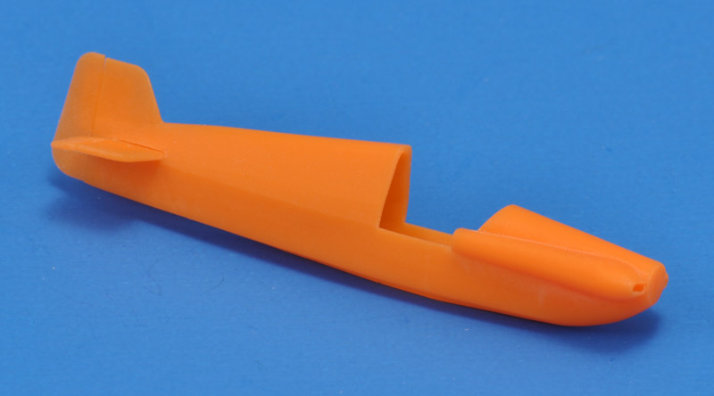
The brittleness of the 3D printing material is another problem. I once dropped a fuselage half from 4 cm height, and it broke it two. I also broke an aileron that was already attached. Luckily that break was so brittle, that the parts fitted perfectly, and I managed to repair with thin CA, without a trace.
an advantage not foreseen is that variants are relatively easy to produce. But that means building multiple examples of the same model, and that's something I rarely do, with the exception of the AQM-34 Firebee
I may want to make a resin-cast model from the 3D printed parts