Own design 1/72 Cassutt 111M
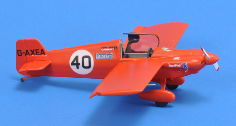
A couple of years ago I ordered two 1/72 Formula 1 pylon racers from Civilized Models (via Wayback Machine), run by Gary McRorey (although my PayPal invoice said 'Curtis Embrey'). Like so many others, I got burned: no kits and I lost my money. The Formula 1 racers remained on my mind: I love tiny aircraft, pylon racers often have great color schemes, and technically it's also an interesting subject. I had great drawings of the Cassutt 111M, but I had never designed a complete aircraft shape in 3D CAD. The Cassutt looked like an excellent test case. One problem however is that nearly each Cassutt is different - welcome to the world of homebuilt aircraft.
3D CAD & 3D printing
1/72 model construction
Aftermarket wings
|
The Cassutt Formula One pylon racer
In 1954, Tom Cassutt first flew his own racer for the 'Formula One' pylon racing class. It had race number 111 and registration N20N. Following a common naming convention, the aircraft was called 'Cassutt Special'. Tom later built a more extreme version, with thinner wings and lower weight, first flown in 1959. It had race number 11 and registration N111U. This aircraft was called the 'Cassutt Special II'.
In 1960, Tom Cassutt started selling plans for his designs. The plans aircraft was called 'Cassutt 111M', '111' from the race number and 'M' for modified since the plans are of a developed version of N20N. Confusingly, the '111M' designator is often written as 'IIIM' which would read as '3M' if you see 'III' as Roman numbers. The plans included one extra sheet for the extreme version, called 'Cassutt 11M' (or 'IIM') in the same style as the 'Cassutt 111M', but leading to some confusion which came first.
An early sixties 'Sport Aviation' issue had an article by Don Berliner, with a three view drawing by Bob Pauley, that alerted the world that the drawings were available. The first plans built Cassutt flew around 1964. More than 2000 plan sets were sold, and some 800 Cassutts have been built and flown. Probably less than 30 of these were the extreme 11M version. 80% of all the Formula One racers are Cassutt based. Here are a Cassutt production list with 344 entries and a Goodyear / Formula I / Formula V Racers list.
The plans ownership and support changed hands several times, to 'Southern Aeronautical Corporation' (Miami Lakes FL), then 'National Aeronautics and Manufacturing Co' (Independance MO, later Arvada CO) and 'CassuTT Aircraft' (Valley City UT).
Starting in the seventies, racing Cassutts were often fitted with other wings, like the 'Wilson wing', the 'Stockbarger wing' and the 'Owl wing'. My research on that confusing subject was split off to a separate webpage: Cassutt 'aftermarket' wings. Another development is the use of longer and longer spacers between the engine and propeller, growing from 4" to 12", made possible by lighter composite propellers.
The Cassutt, fitted with a 75 sqft wing and VW engine, was also used in 'Formula V' air racing. The Lasher Renegade I (by Charles Lasher) Formula V racer was largely based on the Cassutt 111M. The 'Formula V' class appears to be dormant since ~2000.
3D CAD design and 3D printing
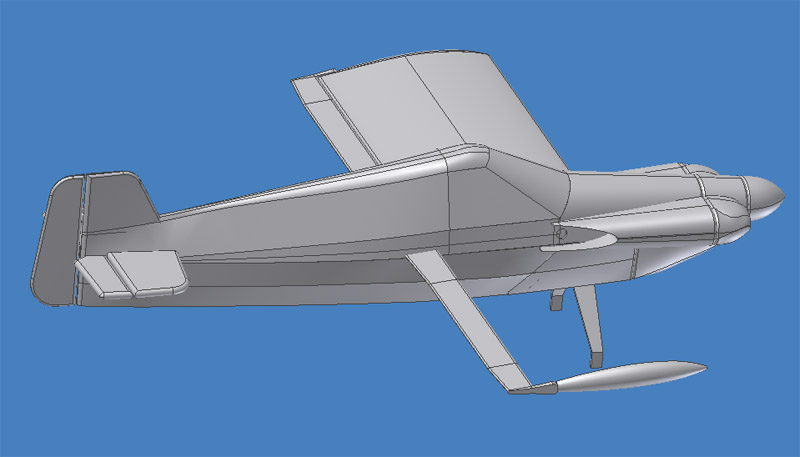
The 3D CAD design of my model is shown on a dedicated page. Shown here is the finished CAD model, with one wing half made invisible.
The CAD model is based on the excellent scale drawings in the May 1970 issue of 'Aero Modeller', drawn by A.A.P. Lloyd. They were later republished in 'Aircraft Archive: Famous racing and aerobatic planes' from 1989. The drawings show the Airmark (UK) built version, more specifically G-AXDZ and G-AXEA. I decided to build the latter.
| 
|
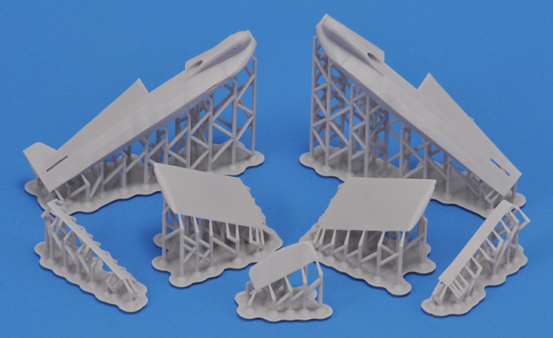
| Club member Wim Hoogendoorn printed the parts for me. Actually this was the second set, but the first set still had some design errors.
|
Construction
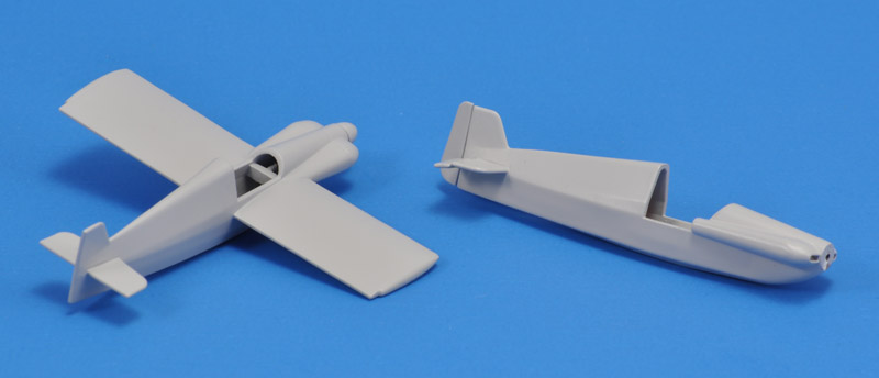
| The fuselage on the right was built from a first, preliminary set of parts. The model on the left is the definitive version. You can see the wing spar running through the cockpit.
| 
|
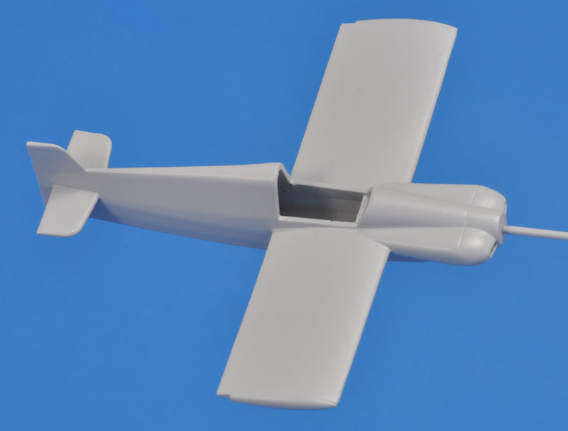
| I assembled the fuselage, and added the wings (minus ailerons) and horizontal tail. It was coated with Tamiya Fine Surface Primer twice; especially the wing needed that since the showed a faint waviness, requiring sanding. I think it looks sweet!
|
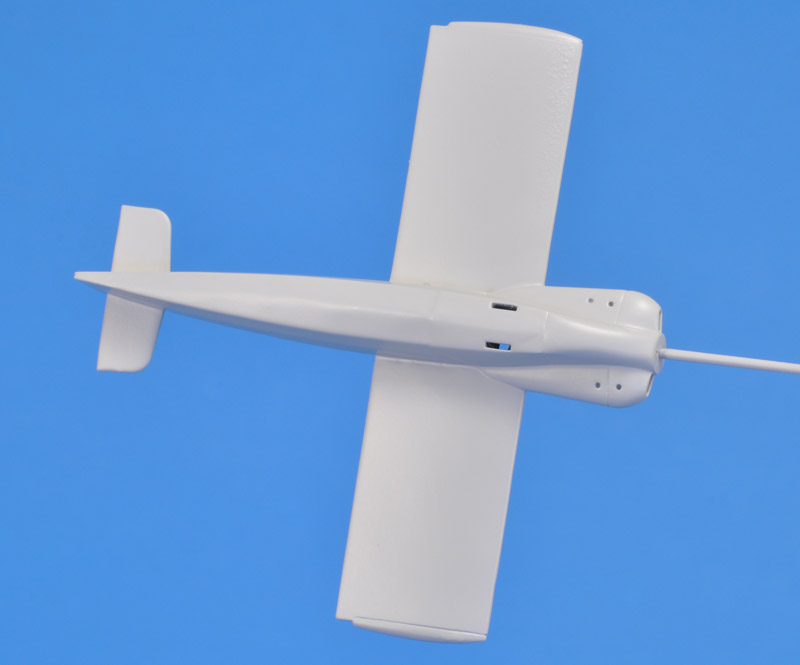
| Details on the lower side include the offset exhausts, and the slots for the landing gear legs. The landing gear legs should connect horizontally, but I'll mount them vertically in the slots.
| 
|
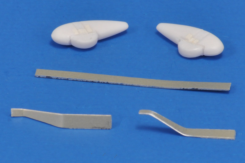
| According to the drawing, the landing gear legs were 6.2 mm long, tapering from 2.0 mm at the fuselage to 1.0 mm at the wheel spat. I had some aircraft grade 0.2 mm strip, that was bent and sanded accordinly. I think this will be strong enough for the tiny model. The spatted wheels are from the LS 1/72 Pitts S2.
|
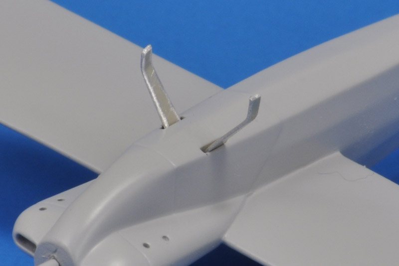
| A first fit of the landing gear legs in their slots. The landing gear legs endured lots of subsequent abuse, but only one leg was ever bent. Great stuff that aircraft grade aluminium!
| 
|
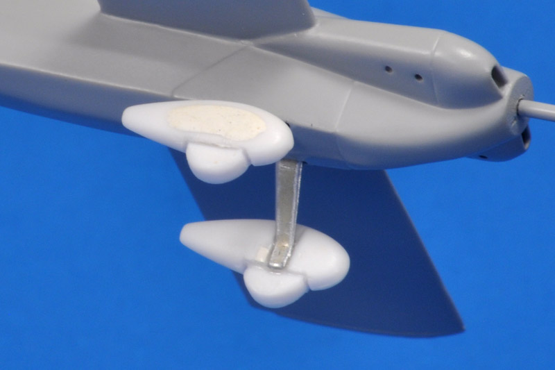
| The legs were attached to the fuselage with CA glue, and the spatted wheels were similarly glued to the legs.
|
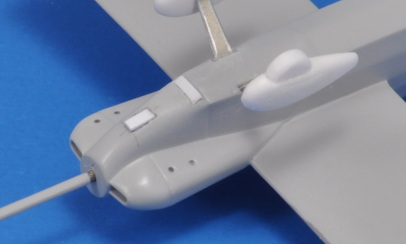
| I had to make a decision what to do with the carburetor inlet and the engine cooling air outlet - the drawings were not very clear about them. I consulted photos and decided on a 1.2 x 0.6 mm strip (2.5 mm long) for the inlet, and a 1.0 x 0.2 mm strip (3.0 mm long) for the outlet. I dug a tiny partial recess for both. A bit of Apoxy Sculpt and / or Mr Surfacer 500 will be required to smoothen things out.
| 
|
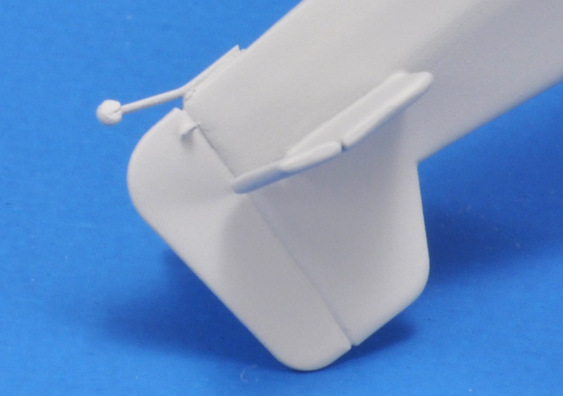
| The tail wheel was 1.0 mm diameter. I searched my spares box, and the smallest wheel I found was 4 mm.. Only then I realised how small the wheel actually was! I then tried making a 1.0 mm disc with my Waldron set, but the results were rough. In the end I switched to regular 1.0 mm plastic rod - much easier. I cut a tiny slot in the piece of rod, big enough for a 5.5 mm long piece of 0.2 aluminium of 0.5 mm width, with a kink in the middle. That tiny part was CA-glued to the lower fuselage. It's pretty sturdy!
|
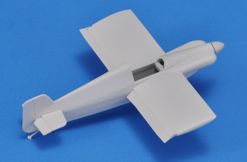
| Then all control surfaces were added. The rudder is straight, the elevators hang down a litle, and I overdid it with the aileron deflections, wanting to show them off. I broke one aileron in the middle after gluing (how?) but was able to glue it back seamlessly. Two rounds of MRP-84 grey primer were used to blend the control surfaces in. The elevators are far too thick, but I'm still learning where the lower limits are with 3D printing.
| 
|
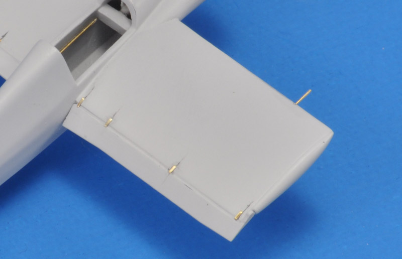
| Another small detail were the aileron hinges, in reality simple steel straps around the aileron torque tube, screwed to the wing skins. I used some random photo-etch pieces, 0.9 x 0.4 mm small, sixteen pieces. Another tiny detail is the 0.3 mm pitot tube, again Albion micro-tubing.
|
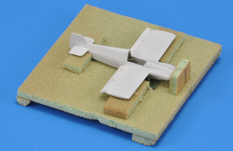
I had postponed detailing the cockpit, but I could no longer avoid it. The model was very delicate to handle by now, so I built a crude handling jig from very old PVC foam. That worked really well, but foamboard would have been nicer.
I started the work on the cockpit by gluing the top longerons inside the cockpit. I used 0.3 mm Albion micro-tubing.
| 
|
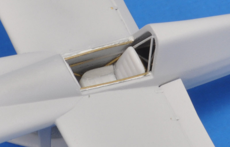
| Next I glued a 'pylon' behind the pilot, resting on the longerons. Adding the 'cross', consisting of three pieces, between the top longerons was ten times more difficult. I added diagonals below the top longerons, and more tubing at the upper edge of the cockpit.
I robbed a seat from the LS Pitts S2 kit, and after some sanding it fitted nicely.
|
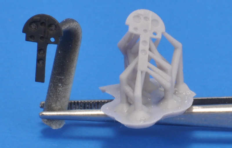
| I designed an instrument based on the Lloyd drawing, but adapted to the space available in the model's cockpit. I painted one of the 3D prints coal black (Revell 9).
| 
|
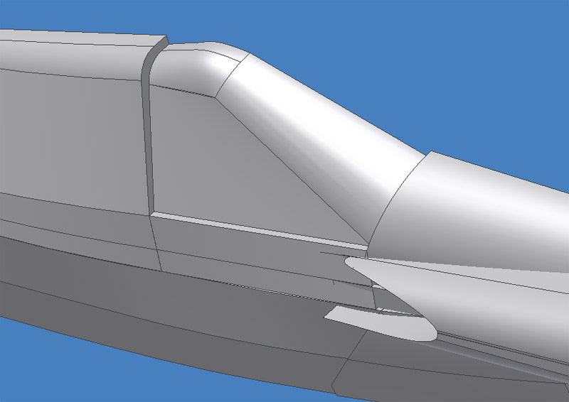
| Work continued on the canopy. So far I only had a true-to-size canopy master, that resulted in oversized vacuum-formed canopies. Therefore I made a new version of the canopy master. It's 0.4 mm smaller in vertical direction, and 0.3 mm laterally on each side. These reductions were measured on a canopy vacformed over the first master, using 0.5 mm PET-G sheet.
|
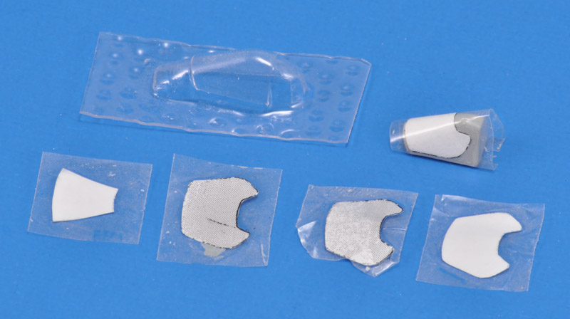
| I designed a custom mask for the 'flat wrap' canopy. This involved a lot of calculations to define the cone-shaped part in the center, see the first paper mask on the left. I then added the sides, but had to fine-tune that in several steps, until I had the one covering the canopy master. The wrinkle-free tape demonstrates this is a true 'flat wrap' canopy. Club member Jan de Wit subsequently cut masks on his Silhouette cutter.
| 
|
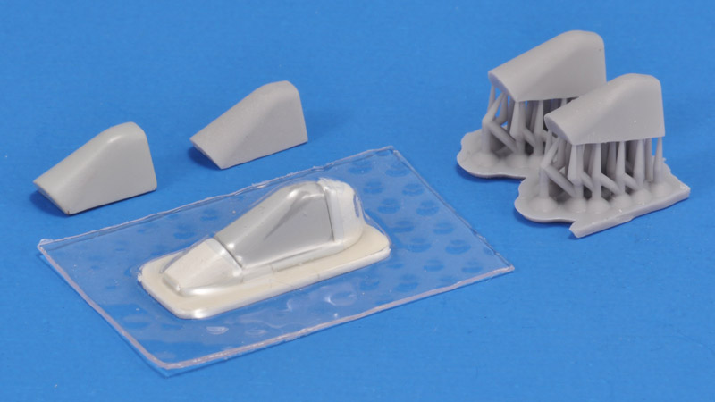
| The true-to-size canopy master is seen rear left, an undersized canopy master rear center. More 3D prints of the undersize canopy are seen on the right. In the front you can see a primed and sanded undersized canopy master on its dedicated support, and a piece of 0.5 mm PET-G vacformed over it.
|
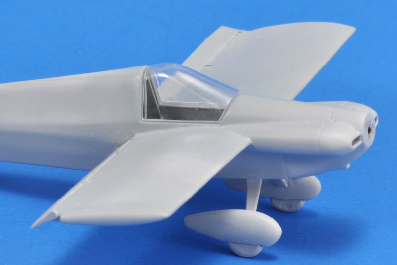
| Cutting out a vacformed canopy is never fun, but at least I had the master to put in it, to see where to cut. The fit just needs a tiny bit of sanding to be perfect. The clarity is very nice, so the cockpit detail is still visible.
| 
|
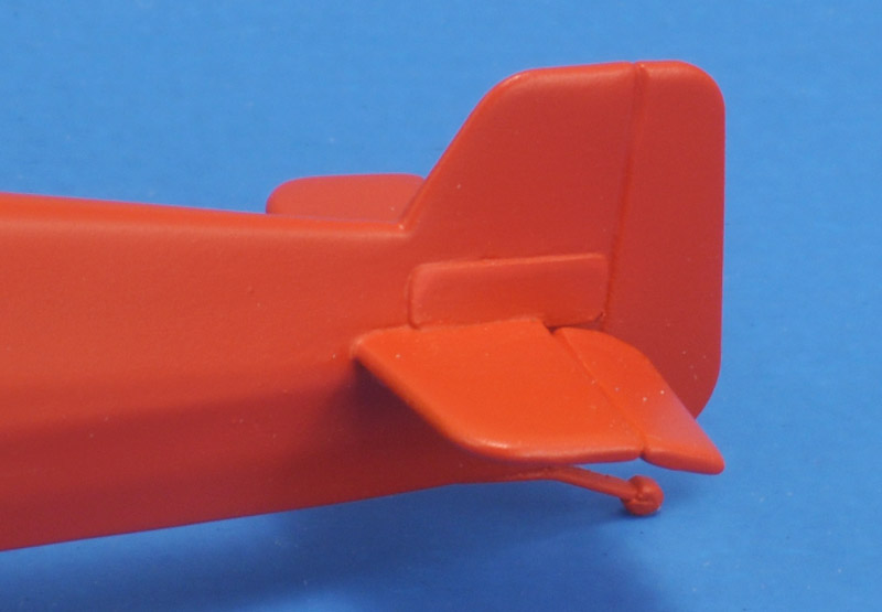
| The last fuselage detail were metal hatches on either side of the fin. I used 0.13 mm plastic card, but it still looks massively thick in the photo.
|
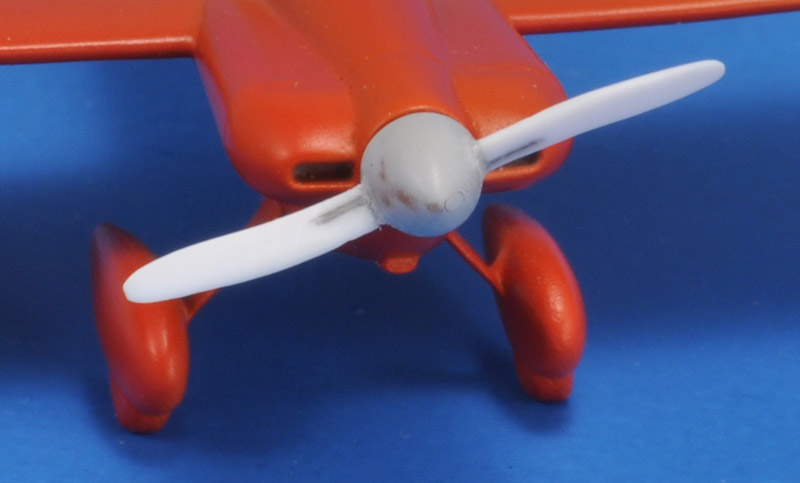
| The 'scimitar' prop blades were made from those of the LS Pitts S2 (again). They were too thin to drill a hole in, instead I cut a slot for the 0.3 mm spring steel wire, CA'd in place. Similar holes were drilled in the 3D printed hub, followed by lots of wire bending to get the blades in the right position. CA glue fixed the wires in the hub and filled any remaining gaps.
| 
|
Paint and decals
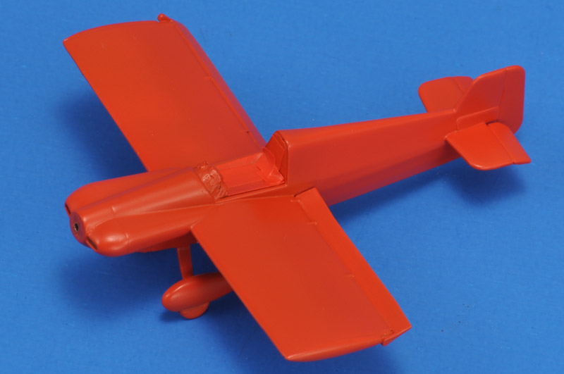
| The photos of G-AXEA on the ABPic site showed a color alternating between red and orange, depending on film used, lighting, etcetera. I decided to mix MRP-194 Signal Red and MRP-232 International Orange in a 2:1 ratio. I liked the resulting color. The cockpit was masked with a combination of Tamiya tape amd Blu-Tack.
| 
|
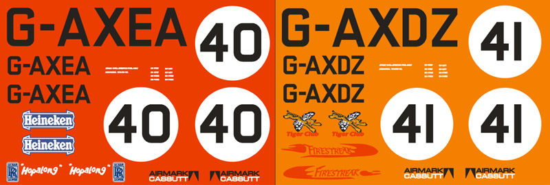
| In parallel with the 3D CAD work, I designed the markings of G-AXDZ and G-AXEA and as shown in the Lloyd drawing, using an old version of CorelDraw. I added a few markings seen in photos, that were added later. This included the logo of Heineken, who were the British air racing championship sponsors in 1973 and 1974.
I found a few webpages with G-AXEA content:
|
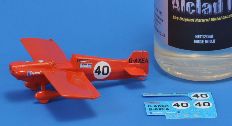
To prepare the model for decals, I applied Alclad ALC-310 Klear Kote Gloss. The MRP paint was glossy enough for decaling, but I've experienced slight discoloring of the paint by the Future floor polish that I use in the decaling process. The clear coat is mostly meant to prevent that. A drawback of these Alclad clears is that the model remains sticky. It picks up dirt - not good. It's probably the last time I used it.
The SpotModel-printed decal sheet looked great, but it had a nasty surprise: the decals curled up like crazy. I managed to salvage the situation with Future: I put a drop(let) of that under each decal, that dries quickly, and becomes tacky. While continuously uncurling each decal, there comes a point where the Future kicks in, and holds the decal down. But what a stressful and labourious job, I nearly gave up. It was a good thing that I had two sheets: I needed three decals from the second sheet.
Update: SpotModel will print a replacement sheet, since there was a 'parameter problem' when my decal sheet was printed. Excellent customer service!
| 
|
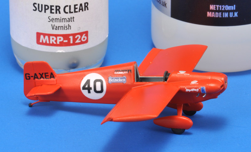
| I never know what clear finish to use, especially since the clear lacquers that I have have misleading names if you ask me. I started with MRP-126 Semimatt Varnish. It had a nice sheen, but I noted by accident that it stayed soft and could be damaged very easily, way too easily. In an attempt to save the situation, I went back to Alclad clears, ALC-312 Semi-Matte this time, and sprayed that over MRP-126, hoping for the best. It worked, but again I had a slightly sticky model, that picked up tons of dirt particles. It's basically unworkable.
You can still see traces of the fight with the decals. The extensive use of Future for its tackiness as it dried left some roughness, for example between the 'Airmark Cassutt' and 'Heineken' decals.
|
Last details
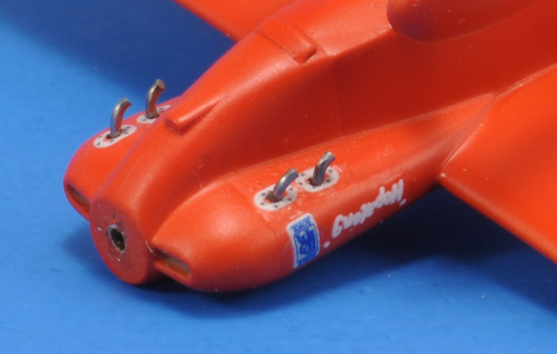
| A close-up of the four exhausts, with decals around the openings, and 0.5 mm spring steel wire exhaust pipes. On the cowling you can see the Rolls-Royce logo and the 'Hop-a-long' name. The Spotmodel printing allowed these tiny details to be reproduced nicely.
| 
|
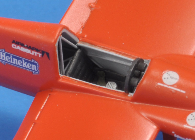
| Here's the cockpit with the seat installed, with hip belts. The shoulder belts are still lacking.
|
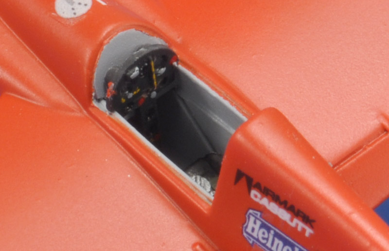
| A view of the tiny instrument panel. The fuel gauge in the shape of a vertical clear tube is best visible, the instrument dials are rather indistinct. The control stick wasn't mounted yet.
| 
|
Finished
| The model was finished just in time for Euro Scale Modeling 2024. It was part of our IPMS-NL regio Zuid-Holland stand, that revolved around the 'Racing' theme. I'm pretty sure it was the smallest model on the tables :-)
| 
|
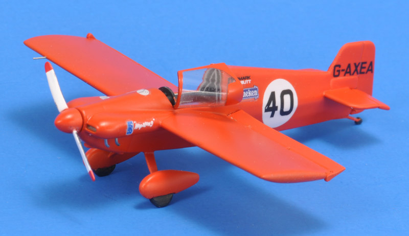
| I think the model looks a bit strange from the left side, due to the open canopy.
|
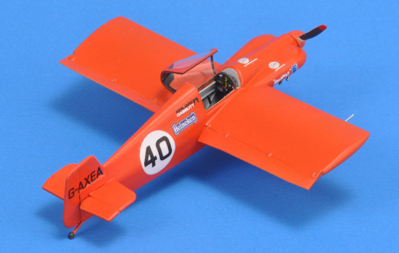
| The open canopy allows a reasonable view in the cockpit. The 'plank' wing still looks slightly strange to me, and it would be nice to build another Cassutt with a more advanced Wilson, Stockbarger or Owl wing.
| 
|
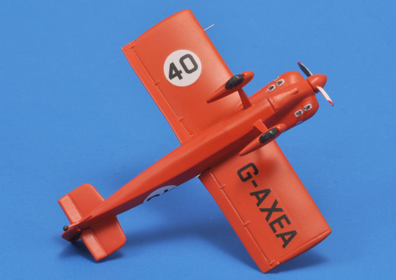
| The lower side shows the racing number, registration and the exhaust details.
|
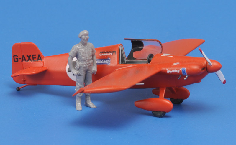
| To show the size of the aircraft, I posed a figure next to the Cassutt. The only standing figure at hand was a USAF policeman from a Hasegawa set.
| 
|
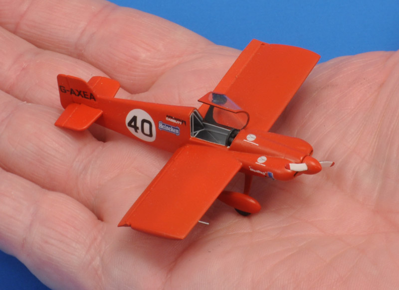
| Another way of demonstrating the size is that I photographed the model on my hand. Unfortunately the seat had dropped out :-)
|
Links
Cremona / Maxwell diagram
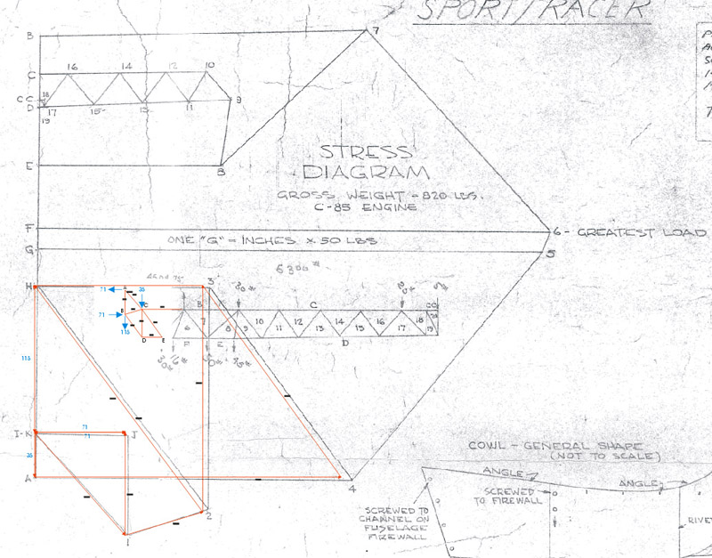
In a 89-page forum thread on the Homebuilt aircraft forum, I found a partial view of the original plans, showing the Cremona or Maxwell diagram for a fuselage side, for a single loadcase. Bow's notation is used for the identification of the members. I'm not 100% sure what loadcase, but it looks like balanced 1G flight, with half the mass and aero loads acting on one fuselage frame side. The drawing set contains two Cremona/Maxwell diagrams, this one is probably for the Cassutt 11M (not 111M), the more extreme version with a thinner wing, narrow fuselage and lower weight. There are several forces noted in the diagram that I don't understand, or can't read properly. I assume the idea is to multiply the resulting tube loads by limit load G and ultimate load G, and then check each tube for yield / break stress and buckling.
I had never drawn such a diagram before, but I have several old aircraft engineering books that explained the process. I made the first one with pencil and paper, but found out one needs to draw all angles very accurately for the diagram to work. I switched to CorelDraw, overlaying the original diagram with my calculations in red, and got a much better result. I only did the front part of the fuselage, to see whether I could reproduce a part of Cassutt's graph. The agreement is not bad I think, considering the drawing wasn't reproduced (scanned or photographed) very accurately.
I do wonder how this analysis translates to the full fuselage truss, where the sides are canted. Also, it's still a simplified analysis assuming pinned joints, whereas the real fuselage has welded joints of course. But that is / was standard practice in aircraft engineering, using a suitable (reduced) factor for the end conditions.
| 
|
Return to models page


