USAFE TAB-VEE shelters and their genesis
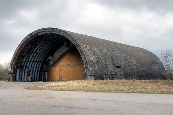
Hahn photo by Ron / Niederrhein Aviation Society (posted on Panoravia, via Wayback Machine)
Part 1: TAB-VEE shelters and their genesis
Part 2: Soesterberg TAB-VEEs walkaround
Part 3: shelter scale models
| I've always been intrigued by the idea of building a 1/72 scale version of a USAFE TAB-VEE shelter, like I had seen at bases like Spangdahlem, Ramstein, Hahn and others. In 2020 I started looking for open sources on the subject, and found many documents with detailed information. They also tell how the US aircraft shelter evolved, and I found it fascinating. Hence this report starts in the early 1960s. Since these shelters are now 50 years old, and open to the public in many cases (think of Bitburg, Soesterberg, Hahn), I don't think they still are military secrets.
|
Wonder Building Corporation
Aircraft shelters in Vietnam
The USAFE TAB-VEE shelter
Zweibrücken TAB-VEE drawings
CAF Lahr 3rd generation shelter drawings
Soesterberg TAB-VEE shelter construction
Upper Heyford TAB-VEE shelter construction
USAFE shelter census
Other countries
Crew recollections
Wonder Building Corporation
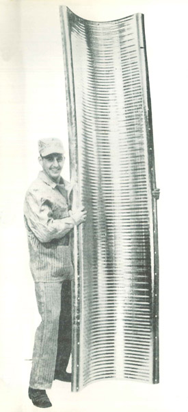
The 'Wonder Building Corporation of America' was located in Chicago (IL). The company is sometimes called 'Wonder Trussless Building Cooperation' but I think the 'trussless' part comes from a logo used in advertisements. Wonder Building Corp produced a line of steel arch elements that were used to build roof structures, usually called a 'Wonder arch' or a 'Wonder roof'. They were used to build small factory halls, warehouses, swimming pool halls, aircraft hangars, etc. The archived Wonder buildings - assembly and specification manual (PDF) from 1960 gives a great overview of the civilian applications of this type of structure. Unfortunately, the manual does not describe the arch elements themselves.
More specialized applications of 'Wonder arches' were found on the South Pole, see US Arctic Program Photo Library and Amundsen-Scott South Pole Station. Wonder Buildings also tapped into the private fallout shelter market. In 'Oppenheimer Is Watching Me: A Memoir', writer Jeff Porter states: "The Chicago Wonder Building Corporation was selling two hundred fallout shelters a week by 1961, at a thousand dollars a crack, and had become famous for their 'trussless' form (erect it yourself!)"
I think Wonder Building Corporation no longer exists, but I found a Spanish video of the Erection of a Wonder prefabricated steel building
Although the word is never used to describe the Wonder structures, they are true monocoques, because the 'skin' is the only structural member. I think the idea compares to the Nissen hut, although these had a wooden semi-circular frame (purlin) every 1.6 m, and are thus not true monocoque structures. Similarly, the 'Romney hut' and the 'Quonset hut' have frames / purlins too, and on the Quonson hut the corrugations are mostly horizontal, meaning it does not contribute to the strength and merely serves as covering.
One of modern equivalents of the Wonder Arch is the K-Span. The single-piece arches are made on site, starting with a roll of flat steel sheet. Here's a video of a K-Span in Afghanistan, and another in Czech Republic: Construction of production arched hall. Chinese versions can be seen too: K-Span forming machine and K-Span machine maxine [sic]. Another modern version of the Wonder Arch is Quick Span Arch Building Machine.
Aircraft shelters in Vietnam
Starting in 1968, some 500 aircraft shelters were built in South-Vietnam, to protect the aircraft against ground attacks. These shelters had been developed since 1962 under 'Project 1597' ('Protective Shelters for Tactical Aircraft') and 'Project Concrete Sky', and used the Wonder arch structure as a main component. A number of articles and books contain solid information about these Vietnam shelters. But first a quick view in three pictures how the Vietnam shelters were built.
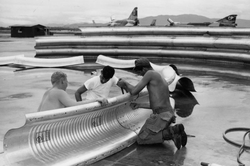
| First, the sheet metal arch elements are bolted together. The pictured elements were produced by US Steel (USS), whose logo is printed twice on each element. Element length varied per manufacturer, and these look rather short to me. The bolting, with 33 bolts per arc element connection, made construction a laborious process.
Source: Wonder Arch Aircraft Shelters photo series on Flickr by 'manhhai'
|
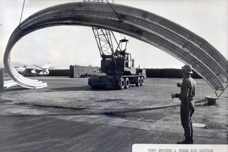
A set of three half-rings is built up and then erected. I roughly calculate a weight of 5500 lbs / 2500 kg. The set flexes a lot during the lifting.
Source: Wonder Arch Aircraft Shelters photo series on Flickr by 'manhhai'
| 
|
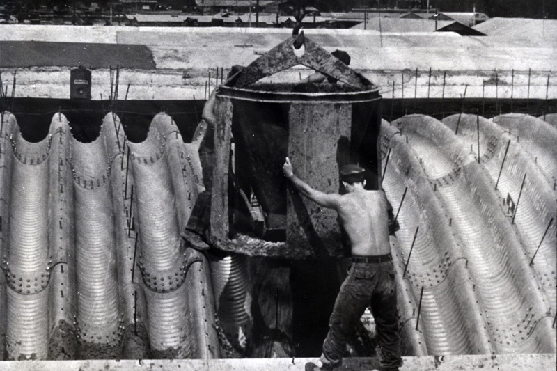
| With the wonder arch structure ready, concrete is poured in 4 feet heights, alternating left and right to avoid too large asymmetric loads on the arch. The top section is not poured inside a casing, but apparently shaped by hand. The rod ends that stick out are probably used to indicate the concrete layer thickness.
Source: Wonder Arch Aircraft Shelters photo series on Flickr by 'manhhai'
|
The book Southeast Asia: Building the Bases. The history of construction in Southeast Asia (PDF) reports on pages 388-390 that:
An Air Force Weapons Laboratory Study concluded their first tests in May of 1965. At that time, AFWL had found one "off-the-shelf" bit of hardware which might work as the basis for further bomb shelter tests. This was the double-corrugated steel arch building made by the Wonder Trussless Building Company. AFWL did further testing with the Wonder Trussless steel arch, using various materials for covers - meaning impact protection and insulation on top of the steel, between 1966 and 1968. Tests were at Eglin, Kirtland and Hill Air Force Bases. The materials used for reinforcement against blast and penetration were earth, soil cement, sandbags, and concrete. The extra emergency of the Tet Offensives lent urgency to the needs — many aircraft were destroyed and damaged by enemy rockets, mortars and artillery in many types of revetments then in use in Vietnam. The AFWL conclusion was that an 18-inch cover of 3,000 psi unreinforced concrete on top of the Wonder Arch would provide the most suitable aircraft shelter for Southeast Asia.
The USAF construction project ran from July 1968 to January 1970
The Navy construction project started Spring 1969, building 122 shelters in total, at Da Nang, Marble Mountain Air Facility (a.k.a. Da Nang East) and Chu Lai
shelter cost was around $30,000 each
The Checo Report: The Air War In Vietnam 1968 - 1969 reports on page 73:
While 34 aircraft were destroyed in 1968 and 91 had major damage, the figures for 1969 were 6 and 10, respectively
The initial shelter purchase for the Southeast Asia program was the steel arch "Wonder" shelter which had proved successful in tests at Eglin AFB, Fla. Ten of these structures were contracted for and were on their way to Vietnam by 17 February 1968. It was decided to cover these shelters with 12 inches of concrete which would make them sufficiently strong to withstand a 122-mm rocket impact, later changed to a 15-inch cover of 3,000 psi concrete. The program was subsequently expanded to 392 shelters.
Other changes took place during the construction process. The initial shelters were to be 68 feet long, 50 feet wide, and 28 feet high. The length was changed to 70 feet in May 1969 to accommodate a jet blast deflector.
.. the overall cost per shelter remained at approximately $27,000.
The four-page article Protective aircraft shelter (Air Force Civil Engineer, Volume 10) from May 1969 gives a nice overview of the shelters built in Vietnam. Here's a summary of the technical aspects:
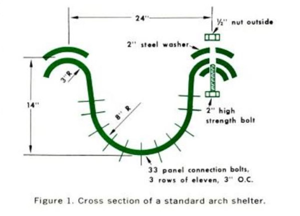
dimensions
fits inside the 52' space of a standard earth-filled steel revetment as used in Vietnam
48' clear span. I read that as the internal space
standard length 72' without front enclosure (as used in Vietnam), 100' with front enclosure
enclosures
front enclosures of steel, aluminum and ballistic nylon [curtains] are being tested
standard rear enclosure is a reinforced concrete backwall with a jet exhaust port
practical Vietnam rear enclosure is the existing revetment, combined with a curved jet blast shield
steel arches
double-corrugated arch elements of 10 gauge (0.1345" / 3.4 mm) steel, 2' wide and 6' to 13' length
arch elements start as a sheet of 46' width, rolled to the shape seen right. Then they are rolled again to create 3' x 1' cross corrugations in the large-radius side, which creates a 24' radius
steel arch elements are bolted together
four steel arch suppliers were found
the steel arch supplier had some trouble producing the specified (thick) gage - new equipment was required
Marwais & Pascoe produced arch elements of ~11'. Each element weighed 265 lbs.
Young Metal Products produced arch elements of ~8'. Each element weighed 200 lbs.
covering
covered by either 4' of earth, or 18" of concrete. The latter is poured using steel slipforms
concrete is poured in 4' steps, but with maximum 2' height difference left-right to avoid heavy unsymmetrical loads on the steel arch
appr. 500 cubic yards (382 cubic meters) of concrete is used for a 72' length shelter
end of December 1968, 35 shelters were produced per week
end of 1968, 120 shelters had been erected in Vietnam. Shelter parts were also shipped to Europe and South-Korea
average cost is nearly $200,000
As an addition to the article, I see two different types of concrete covering. Most shelters have a smooth exterior, others have a corrugated exterior. The reason for this difference is unclear.
'Aircraft Shelters in Vietnam' in The Military Engineer (PDF) gives another overview of the project, and adds that 'Each shelter is composed of 324 panels (with a total weight of 31 tons) bolted together into 36 rings with 15,141 bolts'.
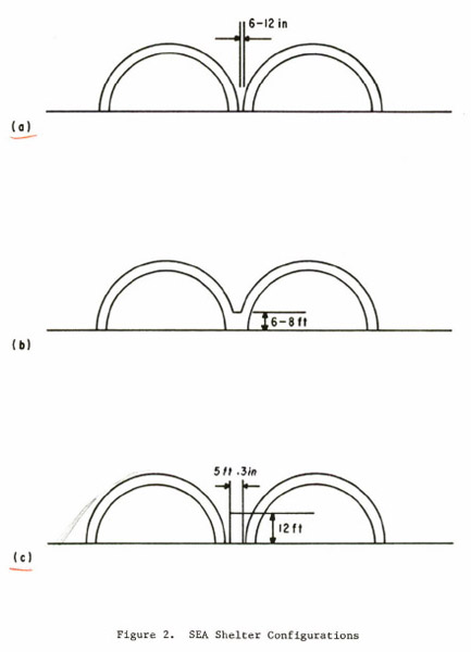
From Aircraft Shelter Explosives Quantity-Distance Evaluation, Concrete Sky, Phase IXB (PDF) we learn some more details of the spacing between the Vietnam shelters:
adjacent shelters are separated from each other by a 6- to 12-inch air gap
adjacent shelters are connected by a continuous pour of concrete up to a level of 6 to 8 feet
adjacent shelters are separated from each other by a steel bin, earth filled revetment approximately 5 feet 3 inches thick and 12 feet high
The book Engineers at War reports that the US Air Force had planned 408 shelters in Vietnam, at six bases, but 392 were actually built: 98 at Da Nang, 75 at Bien-Hoa, 62 at Tan Son Nut, 40 at Phu Cat, 61 at Phang Rang and 56 at Tuy Hoa. The book reports on page 452:
unreinforced concrete, fifteen inches thick on ridges and twenty-nine inches thick in valleys
a freestanding backwall gave equal protection and included an opening to let out jet exhaust
a few shelters could also be fitted with a front closure device
sixteen shelters for Phu Cat Air Base were canceled, reducing the number of shelters to 392
page 453 shows a photo of a corrugated concrete mold, explaining the 'ribbed' exterior of some shelters
Yet another source is the book Air Base Defense in the Republic of Vietnam.
The 510th Fighter Squadron Association - Image Gallery shows several Vietnam shelters consisting of the 'wonder arches' only, without concrete poured over them.
Navy / Marines 'Wonder arches' in Vietnam, 1969 and on
According to the articles below, Seabees construction engineers built forty-five shelters at Da Nang in 1969, then twenty at Marble Mountain Air Facility (a.k.a. Da Nang East), and finally forty at Chu Lai. They were open at both ends. In Google Earth I count 106 (this includes USAF shelters), 21 and 33 respectively remaining at these airfields. Here are two accounts of the building process, with photos:
The shelter sizes are not mentioned, but they were most likely identical to the 48' USAF shelters. In Google Earth, I measure approximately 51.5' / 15.7 m exterior width, taking the shelters in the north-west corner of Da Nang for the measurements. As far as I could find out, the Air Force used the east side of the base, the Marines the west side.
Another source is: Building the Navy's Bases in Southeast Asia (PDF), pages 388-390.
The USAFE TAB-VEE shelter
TAB-VEE is short for 'Theater Air Base Vulnerability Evaluation Exercise'. Note that TAB-VEE is also written as 'TAB VEE', 'TAB/VEE', 'TAB-Vee' or 'TAB-V'. This program was started in 1968, following the Arab-Israeli war of 1967, and the Vietnam war experiences. Its aim was to provide better protection for USAFE airfields. It involved better protection for aircraft, runways, ammo storage and other aspects of air bases. Judging from reports online, the design was designed for a conventional bomb to explode near it, but not for a direct hit with one. A submunition or a rocket could be sustained. It could definitely not withstand a nuclear attack.
Building for peace: United States Army Engineers in Europe, 1945-1991 (PDF) (page 160-161) reports that construction started in 1969, and by April 1972 324 TAB-VEE aircraft shelters had been constructed at Ramstein, Sembach, Bitburg, Spangdahlem, Hahn, Erding, and Zweibrücken (all in Germany), Soesterberg (Netherlands), Aviano (Italy) and Incirlik (Turkey). Air Force Engineering & Services Quartely, November 1977 article reports that the grand total of TAB-VEEs built at USAFE air bases was 396, but so far I've counted 353 (see census below). I also learned that not all shelters were used for aircraft, some were used for ground equipment or weapons. Note that the TAB-VEEs built in Korea had no doors.
As far as I understand, these first generation shelters were identical to 'Concrete Sky' shelters built in Vietnam, with the addition of a back wall and internal clamshell doors, which required an increased length, from 72' to 100'. The internal length was appr. 90', and the inside width was 48'. However, the clamshell doors reduced the last number to 42' or 43'. The shelter was suitable for all then-current TAC aircraft: F-4E (length 63'0", span 38'5"), F-111A (length 73'6", span swept 32'0") and A-7D (length 46'2", span 38'9"), plus any smaller aircraft of course. A small cutout in the inside of the shell had to be made to make room for the upper hinge of the clamshell doors. This was compensated with two concrete patches on the exterior (see opening photo).
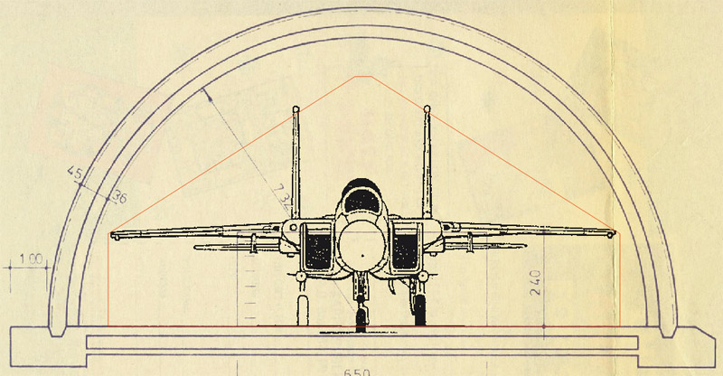
During the construction process, it became clear that the F-15, that was under development (length 63'9", span 42'10"), would be an extremely tight fit in the clamshell door opening, leaving one inch on either side. I've read that floor rails were fitted to guide the aircraft, but I haven't seen photos that prove this. The double fins (18'8" tall) also present a problem, if my drawing below is correct. To solve the problem, a new door was designed, moving the clamshell doors to the front edge of the shelter, where they were welded together and made to slide sideways. This design was built at a few air bases: Bitburg, Incirlik and Soesterberg. These shelters are called '1st generation (modified)' shelters.
|
An analysis of the fit problem of the F-15 passing through the door opening indeed shows a height problem.
|
Although heavily redacted, Military Construction Appropriations for 1975 give an impression of the era of transition from the TAB-VEE to the next shelter designs.
I think that the F-111 actually required a shelter where it could be parked with the wings swept forward (span 63'). Therefore, the introduction of the F-111 in USAFE lead to the 2nd generation shelter, that was probably no longer called TAB-VEE, but Hardened Aircraft Shelter (HAS). Its 124' x 82' internal dimensions more than doubled the floor area. The shelter's cross section has a compound radius, by combining arch elements of two radii. The second generation retained the 18-inch concrete roof covering; therefore, the shelter still did not protect against direct bomb hits. The design was not intended to defeat precision attack, nor nuclear attack. The doors were 1' thick concrete, sliding sideways, with a steel spaceframe for stabilization. A strange aspect of the door is that they are smaller than the shelter; there is a partial front wall to fill in the remainder (see Quintin Lake photos). The original design (not built) had a different recessed door system, consisting of four hinged sections, operating like 'Dutch doors', as in German shelters. This type was only built at Upper Heyford, 31 pieces, around 1976-1977 I believe. See Air Force Engineering & Services Quartely, November 1977 article.
For reasons I haven't been able to reconstruct, the 2nd generation shelter was very quickly replaced by the somewhat smaller 3rd generation shelter. It shares nearly all design details with the 2nd generation shelter, but internal dimensions are 120' x 71' instead of 124' x 82' (i.e. 84% floor area). For this type we know how the compound radius was made: the middle has a radius of approximately 45' radius over a 66 degrees arc, that connects to 24' radius arcs on either side, that connect vertically to the floor. The third generation shelter was also easily big enough for the next type to be added to the USAFE inventory, the A-10 (length 53'4", span 57'6"). All USAFE shelters constructed after the 2nd generation shelter were of this type. For the fiscal years 1976 to 1978 350 shelters were to be built according to Air Force Engineering & Services Quartely, November 1977 article; I counted 31 + 367 = 398, but this includes shelters for the A-10 Forward Operation Location program that did not yet exist in 1977. Protection levels were the same as before, see High Explosive Testing Of Hardened Aircraft Shelters (PDF), with an interesting observation that the inside steel exhaust doors went flying in one test. DoD 'Approved Protective Construction (Version 2.0)' (PDF) also discusses the same shelter tests.
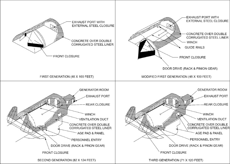
From: Tech Order 00-25-172 'Ground Servicing Of Aircraft And Static Grounding / Bonding' (PDF)
|
|
Internal dimensions
|
External dimensions @
|
Features
|
| 1st generation (unmodified)
|
length 100' / 30.5m *
width 48' / 14.6m
door width 42' or 43'
|
length
width ~53.4' / ~16.3m
|
* internal length with doors closed appr. 90'
Clamshell doors inside the shelter
Personnel entrance through door in left-side clamshell door
Patch on the exterior
I think different types of exhaust deflectors were used, maybe even on one air base
|
| 1st generation (modified)
|
length ~100' / ~30.5m
width 48' / 14.6m
|
length
width ~53.4' / ~16.3m
| Single sliding door, made from repurposed clamshell doors
Personnel entrance through sliding front door, left side
Usually no patch on the exterior
I think different types of exhaust deflectors were used, maybe even on one air base.
|
| 2nd generation
|
length 124' / 37.8m
width 82' / 25.0m
|
length
width ~88' / 27m
|
Personnel door on the right side
Inverted J type ventilation tubes on top of shelter, usually alternating left and right
Concrete apron for ground equipment on the right side, with possibly a lead-through in the shelter wall
Partial front wall, since the doors are smaller than the shelter
|
| 3rd generation
|
length 120' / 36.6m
width 71' / 21.6m
|
length
width ~77' / ~23.5 m
|
Personnel door on the right side
Inverted J type ventilation tubes on top of shelter, usually alternating left and right
Upward-pointing 'wings' on the exhaust deflector
Concrete apron for ground equipment on the right side, with possibly a lead-through in the shelter wall
However, ground equipment is often seen inside the shelter too
|
@ external dimensions are of the arch only, without foundation, door support, annex building and / or exhaust
|
I found some photo reports showing USAFE TAB-VEE shelters:
Google Earth also has lots of excellent photos of shelters made on air bases that are no longer in military use.
A few YouTube links with good details of shelters:
Zweibrücken TAB-VEE drawings
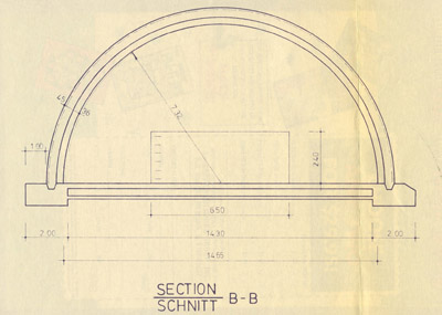
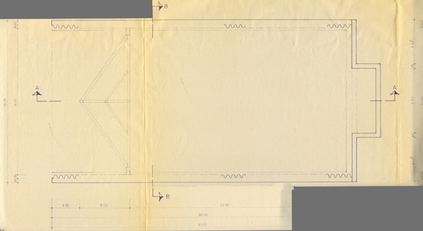
Larry Engesath very kindly sent scans of basic construction drawings, that he saved from his years at Zweibrücken as a camera technician. They clearly show the original 1st generation type, unmodified, with the doors inside the semicircular shelter. Measurements are in SI units.

CAF Lahr 3rd generation shelter drawings
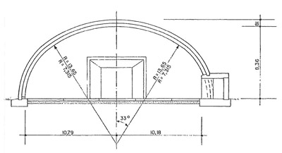
Many years ago, I found a brochure for a 'shelter for rent' at Lahr, formerly used by the Canadian Air Force. As far as I can see, this shelter design is identical the the USAFE 3rd generation shelter. The 3rd generation shelter is often called a NATO standard in official documents, so it's not strange that they are identical.

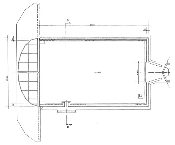
Soesterberg TAB-VEE shelter construction, 1969
The Royal Netherlands Air Force took fantastic aerial photos during the construction of first generation (modified) TAB-VEE shelters at Soesterberg in 1969. I found the photos on the website of the Nederlands Instituut voor Militaire Historie, and put them in an order that shows the construction process from start to finish.
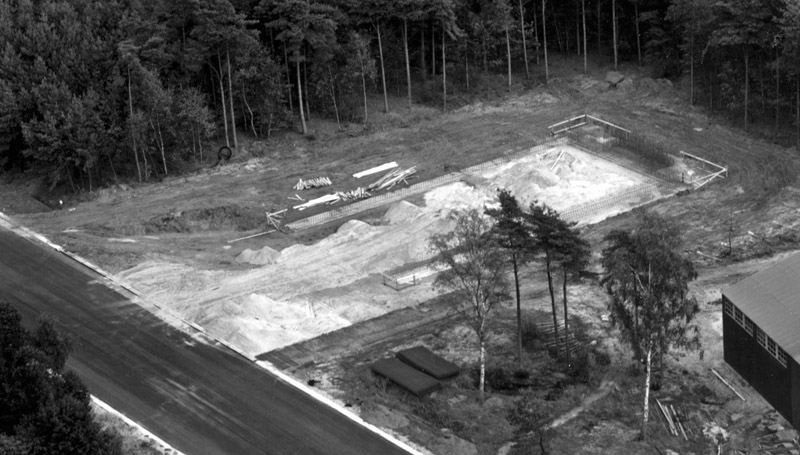
| Start of construction of the foundation. Lots of rebar visible near the exhaust area. Photo courtesy of NIMH.
|
| Concrete edge foundation is cast. The shelter floor has not been laid yet. The function of the black beam across the foundation is unclear. Photo courtesy of NIMH.
| 
|
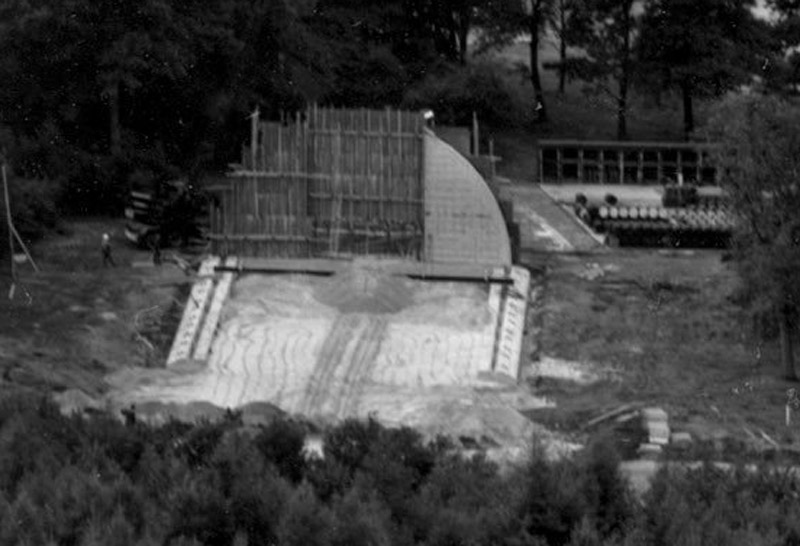
| Casting of the rear wall in progress, using what looks to me like a rather primitive casting mold of narrow wooden planks. The 'black beam' is also visible here. Photo courtesy of NIMH.
|
Rear wall with a flange to connect with the arches. The rear wall has unusual exhaust gas openings. I'm not 100% sure, but I think we're looking at the single shelter that was built with a 150' instead of 100' length. See three photos down for a better view. Generally you will see one of these in each TAB-VEE shelter area. Possibly these unique shelters were not meant for operational use? Photo courtesy of NIMH.
Later I found a photo on the NIMH Beeldbank site that probably shows an operational 'long' shelter at Soesterberg with an office located at the rear of the shelter. I don't know how the exhaust gasses were dealt with.
| 
|
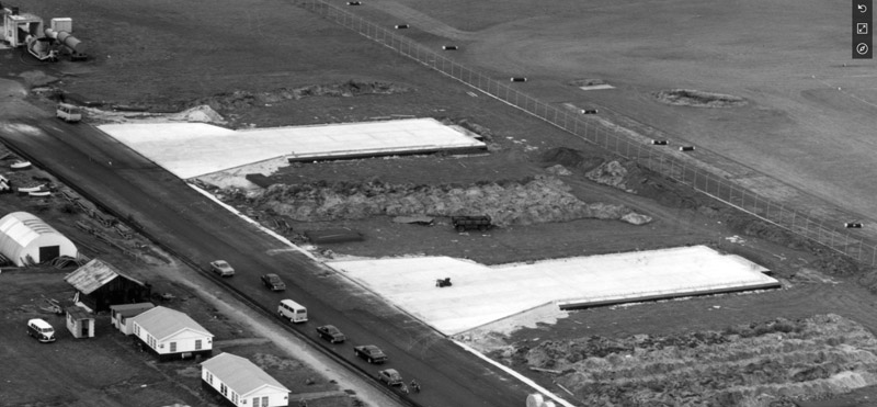
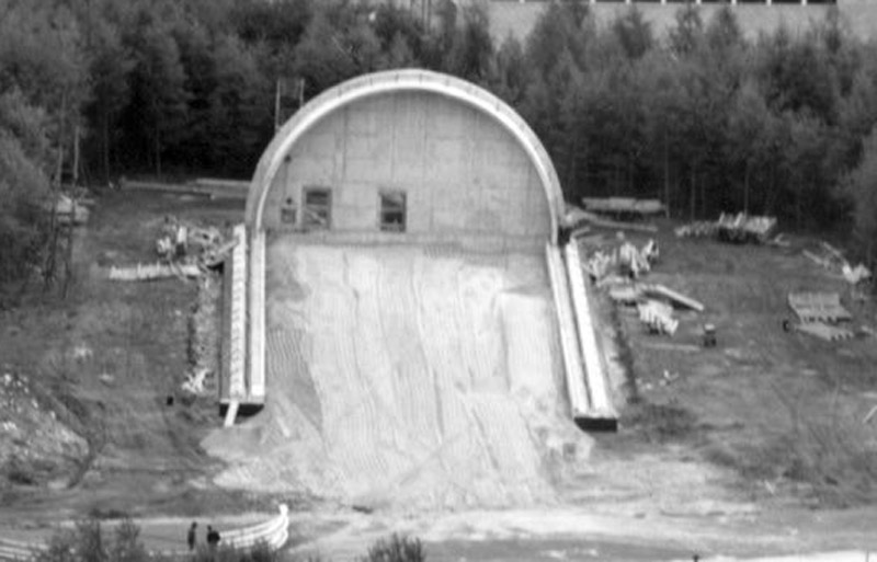
| Some shelters were built with the shelter floor and ramp constructed first. The foundations for the two shelters themselves are also visible. Photo courtesy of NIMH.
|
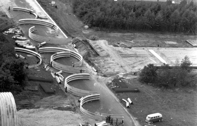
A taxiway is used to assemble the arches. First, the arch elements are bolted together to a single span, then more elements are added until three rows of elements are bolted together.
Since the combined weight of a three-row arch is probably around 5500 lbs / 2500 kg, a crane is most likely used to move the arches to the shelter site. Photo courtesy of NIMH.
| 
|
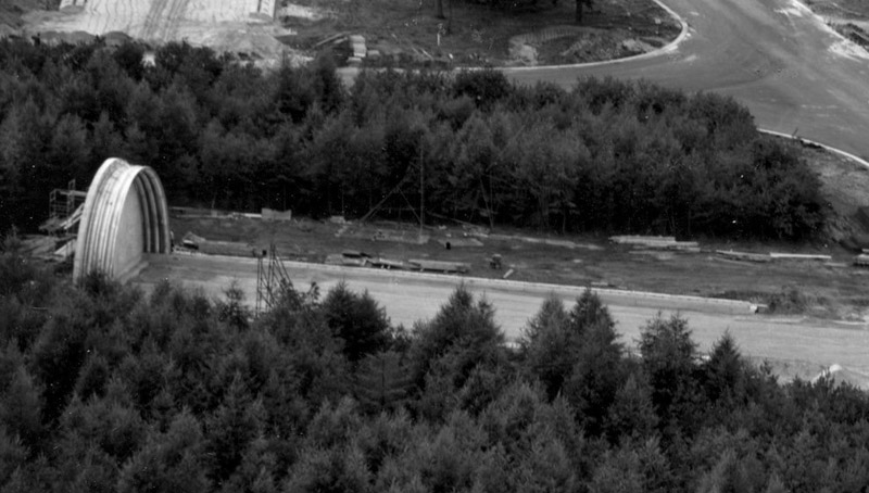
| The first three-ring arch is positioned against the back wall. Interestingly, this photo shows the extra long (~150' length) version. Photo courtesy of NIMH.
|
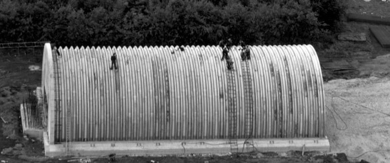
| The complete arch roof has been built up here, against the concrete back wall, that still lacks the exhaust channel. It's not clear what the workmen are doing here, possibly tightening all the bolts? There is no rebar visible on the Wonder roof, but there is rebar for the future exhaust. I count 50 arch elements. Photo courtesy of NIMH.
| 
|
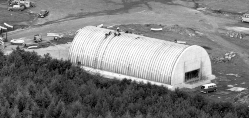
| Another photo of the same stage. The standard exhaust opening in the rear wall is clearly visible here. It's about the size of the VW bus. Photo courtesy of NIMH.
|
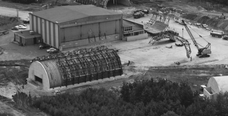
| The outer casing for the concrete pouring is being assembled here. A crane is on its way with the one but last casing element. Each side gets six casings. The casing elements connect to the small dark rectangles on the foundation. On the top side, they connect to the opposing element with a framework. Note that the casings leave the very top of the shelter open; it seems that area is flat enough for concrete to be shaped by hand. Photo courtesy of NIMH.
| 
|
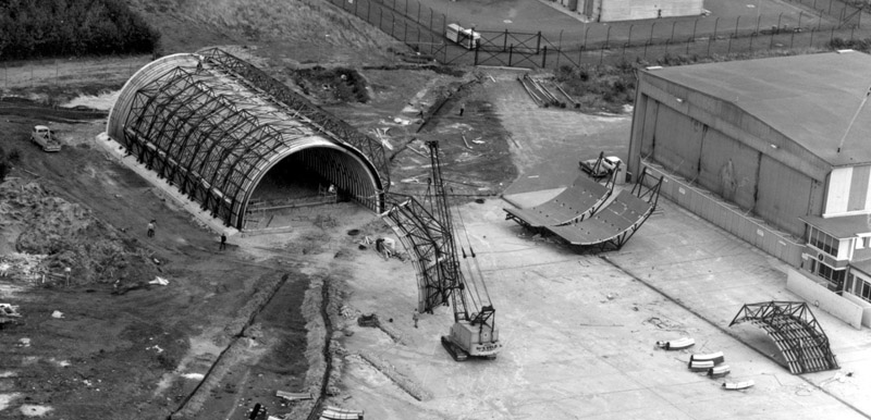
| The same situation from a different angle. There is no casing yet to close the semi-circular slot on the front side of the shelter. We can see that there is no concrete floor in this shelter yet. Photo courtesy of NIMH.
|
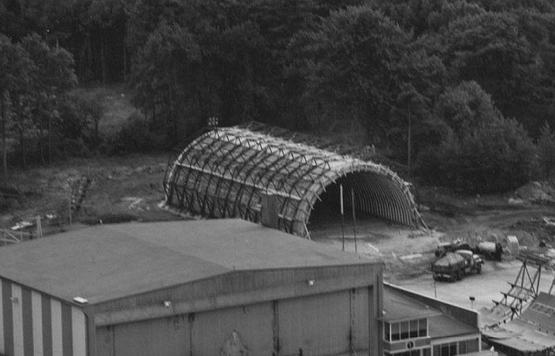
| It looks like the concrete has been poured on this shelter. Again it seems to lack a concrete floor. Photo courtesy of NIMH.
| 
|
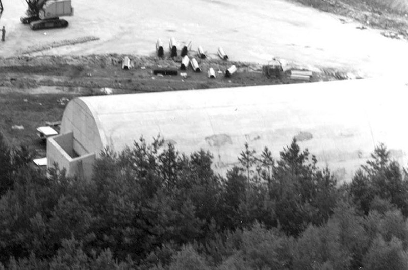
| In this photo the exhaust channel has been added, blowing upwards. You can also see multiple edges of the cancrete casting molds. Photo courtesy of NIMH.
|
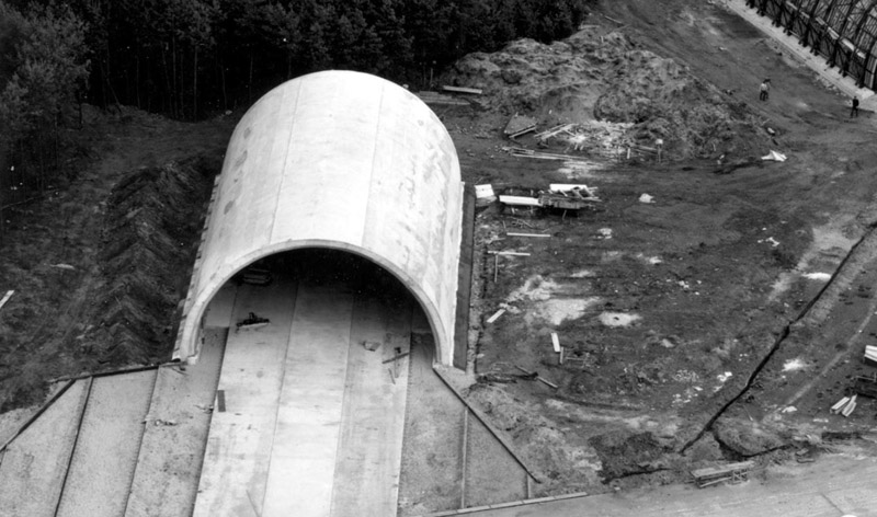
In this photo, construction of the ramp that connects the shelter with the taxiway is underway. I think I see leveled and compacted sand with vertical wooden (?) planks, ready for pouring concrete. Again, no rebar is in sight.
On the shelter itself, the upper edges of the pouring casings can be seen, they leave two ridges on the top of the shelter. Photo courtesy of NIMH.
| 
|
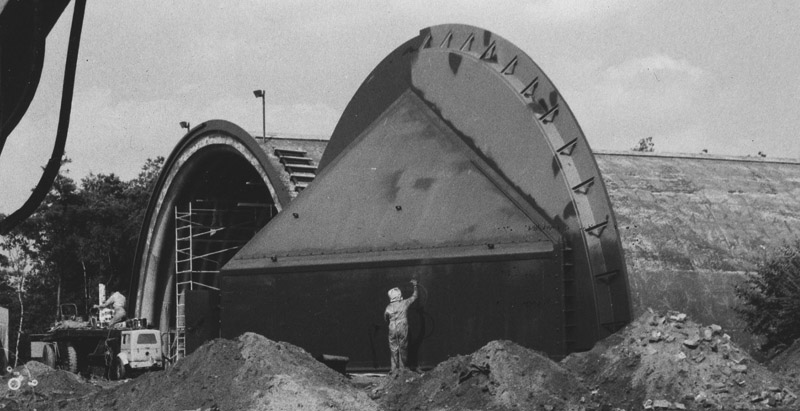
| The Soesterberg 1st generation shelters were built without doors, in preparation of the arrival of the F-15 nine years later. Consequently, none of the photos above show a guide rail on the ramp for the 'external' sliding door. One photo at the NIMH Beeldbank clearly shows a doorless shelter during the F-4E era at Soesterberg. The 1st generation shelter itself was big enough for the F-15, but when the standard internal clamshell doors were fitted, the width through the door opening was marginal, and insufficient in height.
According to Mario Warnaar (author of Slobberin Wolfhounds), the Soesterberg 1st generation were retrofitted with internal clamshell doors starting in 1973. They were removed again around the arrival of the first F-15s in 1978. I guess that the doors themselves were re-used, welded together, with a semicircular part added, probably steel sheet filled with concrete. The illogical shape of the sliding door is the result of this process.
This photo must have been made in that time frame. The single sliding door is being sandblasted or painted here. While closing, the door slides in a quarter-circle channel on the left side of the shelter. This probably also explains the small step in the circumference of the door. Of note is the weathered look of the shelter's concrete shell. Photo courtesy of NIMH.
|
Upper Heyford TAB-VEE shelter construction, 1976
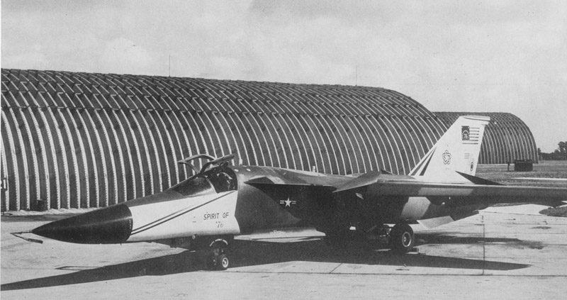
| This photo shows that shelter construction did not always proceed as seen at Soesterberg. In this photo we see the bare 'wonder arches', without concrete, or any signs of concrete pouring to be started.
The different curvatures of the 'roof' and the 'side' shows that this shelter is of the 2nd or 3rd generation. The roof section has additional connectors, compared to the Soesterberg photos.
Photo source: Famous Airplanes of the World No 85: 'GD F-111/FB-111'.
|
USAFE shelter census
I used Google Earth to do a count of shelters on USAFE, Luftwaffe, RAF and Royal Danish Air Force air bases. The stand-alone version of Google Earth includes historical imagery, that was often needed because of demolitions on abandonded USAFE bases. If you have more accurate count(s), please let me know. Air bases indicated # are deployment air bases, only used in exercises. Air bases indicated % are A-10 Forward Operating Locations, used regularly by 81TFW.
|
| 1st generation
unmodified
| 1st generation
modified
| 2nd generation
| 3rd generation
| Comments
|
| Aalborg #
| 0
| 0
| 0
| 17
|
|
| Ahlhorn %
| 0
| 0
| 0
| 17 *
| * ten shelters were demolished in 2021, to make room for an Amazon warehouse
|
| Alconbury
| 0
| 0
| 0
| 26 *
| * all thirteen on the south side were demolished to make room for Alconbury Weald with 5000 new homes. One random shelter on the north side was also demolished.
Additionally 13 super-wide shelters for TR-1 / U-2R
All north-side shelters and hangars are now in commercial use.
|
| Aviano
| 15 *
| 0
| 0
| 35
| * including one 125' and one 150' versions
|
| Bentwaters
| 0
| 0
| 0
| 21
| it is reported that another 20+ shelters were to be constructed on the south-west side. The taxiways and entrance aprons were constructed, and are still extant
|
| Bitburg
| 0
| 66 * **
| 0
| 0
| * an accurate count is impossible since reconstruction is well underway in the oldest Google Earth photos (2009). For example, I see two empty spots that could have been shelters, but I can't be sure.
** at least two 125' and three 150' versions
|
| Boscombe Down #
| 0
| 0
| 0
| 18
|
|
| Erding #
| 18 *
| 0
| 0
| 0
|
* one 150' version.
This is probably the most undisturbed set of first generation shelters
|
| Gilze-Rijen #
| 0
| 0
| 0
| 16
| constructed in 1976 and 1977
|
| Hahn
| 43
* **
*** ****
| 0
| 0
| 2 *****
|
* I count 18 in the south shelter area and 25 north shelter area
** one more in the north-west of the north shelter area, not connected to taxiway
*** one 150' version in each shelter area
**** five demolished in the south shelter area
***** one each in both shelter areas, but the one in the south area was demolished
|
| Incirlik
| 0
| 28 *
| 0
| 21
| * including two 150' versions and one 125' version
|
| Jever #
| 0
| 0
| 0
| 23
| constructed in 1976 and 1977
|
| Karup #
| 0
| 0
| 0
| 28
| 11 in north-west area, 11 in north-east area, 6 in south-east area
|
| Lakenheath
| 0
| 0
| 0
| 60 *
| refurbishment under way in 2022, with the shelter interiors being sprayed white.
* two shelters demolished around 2021-2022, on each for extension of the F-15 flightlines in the SW and SE corners
|
| Leipheim %
| 0
| 0
| 0
| 10
|
|
| Norvenich %
| 0
| 0
| 0
| 10?
| 3 remaining
|
| Ramstein
| 74 * **
| 0
| 0
| 12 *
| * in the east shelter area, five 1st gen shelters closest to the taxiway-turned-runway, and a new apron, were demolished between 2000 and 2010, plus one 2nd gen between 2010-2015. In the west shelter area, the two 3rd gen shelters closest to the taxiway-turned-runway were demolished between 2000 and 2010. In the north-east shelter area, 11 first generation and 1 third generation shelters were demolished between roughly 2005-2015
** including two 150' versions and one 125' version
|
| Sembach
| 0
| 0
| 0
| 13 *
| * one demolished in west area, looks like more will follow
|
| Skydstrup #
| 0
| 0
| 0
| 12
| 7 in north-west area, 4 in south-west area, 1 in south-east area
|
| Soesterberg
| 0
| 18 *
| 0
| 17 ** ***
| * Sixteen 100', one 125' and one 150' version. Six 100' remained in 2012, rest demolished. One more gone by 2016. Two more demolished early 2024, leaving just three. Area with these older shelters is not open for public.
** area open for public, some shelters are open
*** constructed in 1977
|
| Spangdahlem
| 48 *
| 0
| 0
| 24
| * including two 150' versions
|
| Tirstrup #
| 0
| 0
| 0
| 18
| 3 in north-west area, 9 in south-west area, 6 in south-east area
|
| Upper Heyford
| 0
| 0
| 31
| 27 *
| * 9 north side, 18 south side
|
| Vandel #
| 0
| 0
| 0
| 13
| all in south-east area
|
| Wiesbaden %
| 0
| 0
| 0
| 13
| shelter area is converted to an industrial area. Seven shelters remain in 2021, of which two have been 'beautified'
|
| Woodbridge
| 0
| 0
| 0
| 17
| roughly 2010, all shelter doors were removed and scrapped
|
| Zweibrücken
| ~41 *
| 0
| 0
| 0
| * 10 of ~23 remain in the north shelter area, all 18 in the south shelter area are demolished
|
|
|
|
|
|
|
|
| Total
| 239
| 112
| 31
| 470
| Grand total 852 so far. RAND Research Report 968 says: 'By the end of the Cold War, the United States had constructed roughly 1,000 such shelters in Europe and the Pacific'.
|
In the article Reinforcing the UK: USAF Cold War Fighter Deployments (requires an active KeyAero subscription to view), it is reported: "In common with many NATO airfields, a hardened aircraft shelter (HAS) construction programme was planned for these bases but was only completed at Boscombe Down. Proposals to build similar shelters at Coltishall (26), Finningley (26), Waddington (30) and Wittering (26) would, in some cases, have required acquisition of additional land, but none were built at these bases due to the end of the Cold War. Plans for extra weapons, fuel and liquid oxygen storage facilities were also abandoned."
Other countries
The air forces of many other countries built the same type of 1st generation TAB-VEE shelters. So far I've identified Greece, Italy, Spain and Iran. As far as I can see, they all built the 1st generation TAB-VEE shelter. Maybe the size was slightly different, for example at Villafranca I measured ~18 m width, instead of ~16.3 m for the USAF TAB-VEE.
When measured in Google Earth, RAF (not RAFG) shelters have the same dimensions as the USAFE 3rd generation shelters, and a similar door design, but other annex buildings and probably a different exhaust. I do not know how much they have in common with the USAFE shelter - to be investigated.
Crew recollections
Some collected recollections:
On the Britmodeller forum, 'Slater' recalled: When I arrived at RAF Upper Heyford in 1980, our shelters were just plain concrete color. Then, contractors sprayed some sort of brown coating over them. Don't think it was paint.
On the Hyperscale forum, Mark Veile recalled: I was at Spangdahlem 1984-1987, as a WSO (backseater) in 23 TFS, and spent many, many hours sitting in those shelters. My squadron had the 1st gen shelters and the F-4E/G barely fit. I remember the inside being very dark, mostly black from the soot of the smokey J79 engines. There was also a small, maybe 8x10ft, metal 'office' for the crew chief in the back right corner. There were lights up on the walls but they weren’t very bright. I think the lights were the old single bulb in a cage fixture like in gymnasiums at US schools back then. There were maybe 4 on each side about 2/3 rd the way up the walls, not a single row down the middle at the apex. At least that’s what I remember. Good thing we had young eyes in our 20s so we didn’t need bright lights. I know there was a phone on the right wall, when you’re at the front facing the back. It wasn’t too far back from the main door hinge. There were also a couple of wooden pallet racks on the floor with three Mk82 500lb bombs off to the side. Plus other miscellaneous tools and equipment, but generally the floor was clear so that the jet exhaust didn’t blow stuff around as we pulled out. I’m pretty sure there was a fixture on the floor near the rear to engage the tail hook for engine runs in the shelter. I don’t remember if it was recessed into the floor or stuck up from the floor. I don’t remember tripping over it. The may have been a cable across the back, like an arrestment cable on the runway, for the same purpose. I know there was something. I really don’t remember anything specific along the left side. Other equipment would have been the -60 start cart. It had to be moved outside, if it was in front of the wing, after engine start for the jet to get out. There was a specific place on the pad in front of the shelter that was a painted rectangle showing where to park the -60. There was also a fire extinguisher. I’m pretty sure it was the standard roll around kind you see at every airport. I’m not sure if the crew chiefs had a tool box inside somewhere. Seems like there should have been one with basic tools but probably not a big roller box.
Links
Return to models page


